
|
Building the Elevators |
July 12, 2009
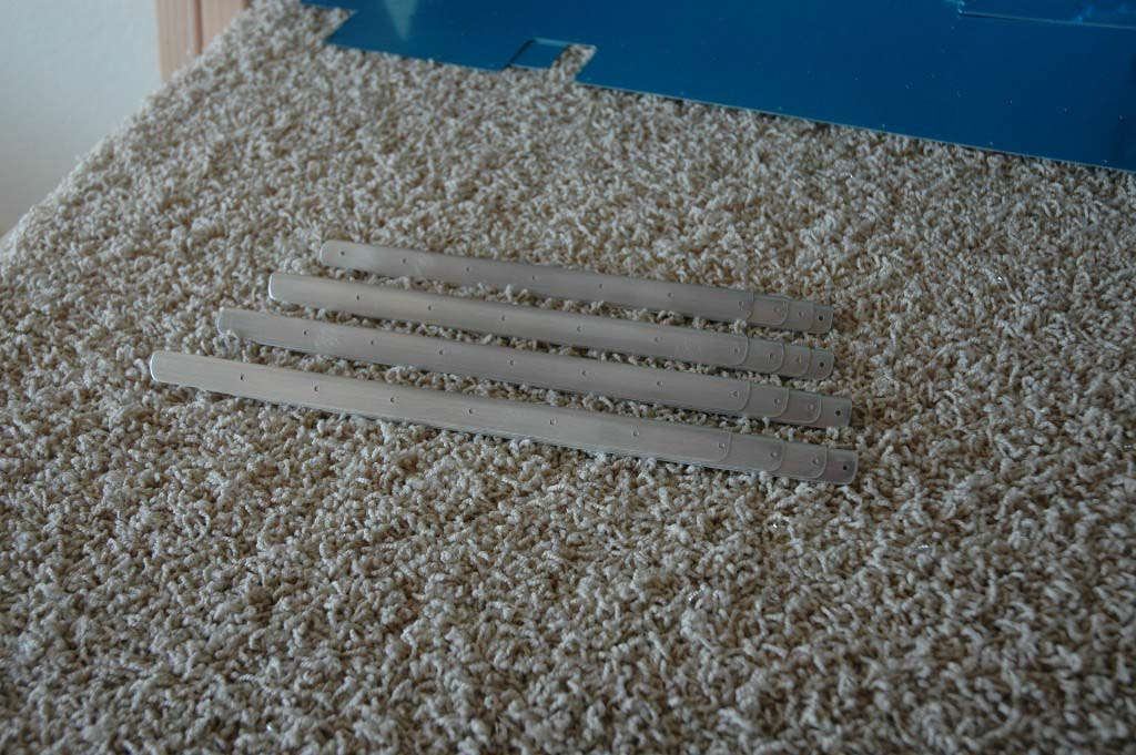
I last updated a few weeks ago...time flies by. In that period I arranged to have an EAA Tech Counselor come and look at my work up to this point. As part of that process, I decided to leave the rudder skin and rudder understructure as they were so the Tech Counselor could look at the disassembled parts. It's hard to inspect something once it is riveted together. So, I decided to set the rudder assembly aside and dive into the elevators. I pulled all the parts down out of the boxes and set them on the workbench, then began poring over the plans and instructions. I had not yet really looked the elevators beyond a cursory look to this point. In actuality, each elevator is like a rudder on its side, except the left elevator has a trim tab, and there are some other complications. However, the construction process starts like the rudder did: fabricate stiffeners from aluminum alloy angle stock, pre-punched, sort of, with where the trim cuts are to be made. There are, like, 28 elevator stiffeners, so it is bit more labor intensive to cut three or four stiffeners out of each piece of raw stock, trimming each one down close to where it needs to end up. Then, using my belt sander, I sanded each one down to fit the plans, then smoothed the edges and used the Scotch-Brite wheel to finish them off. Here is a completed stack:
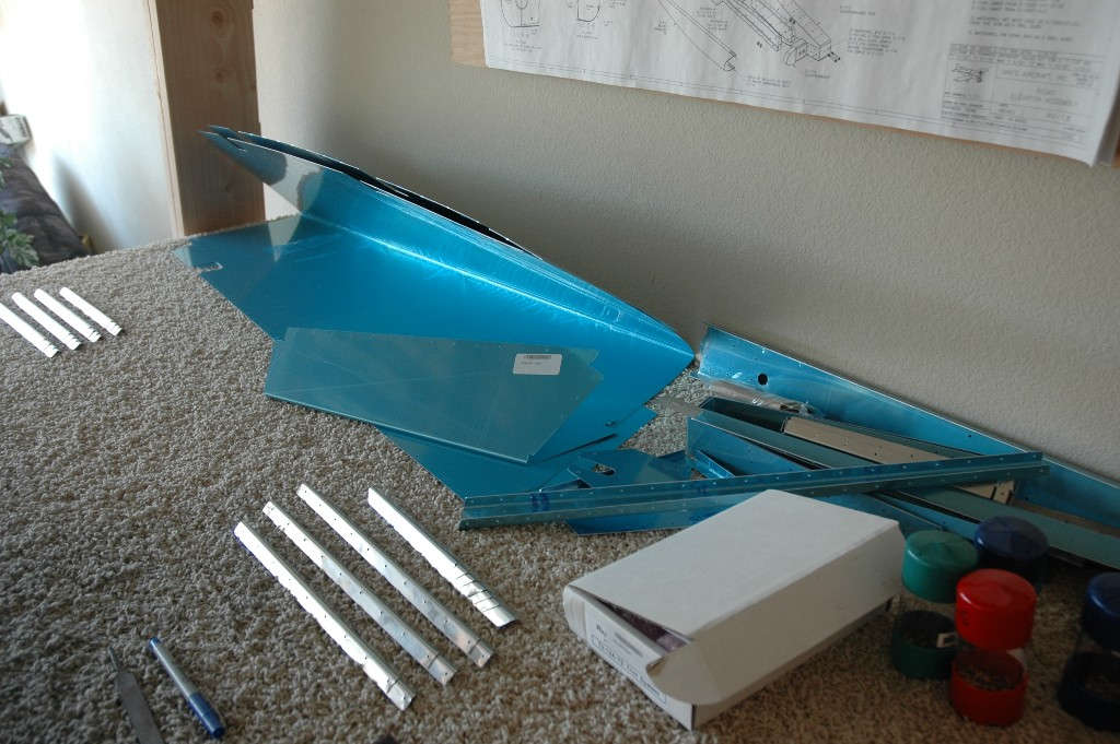
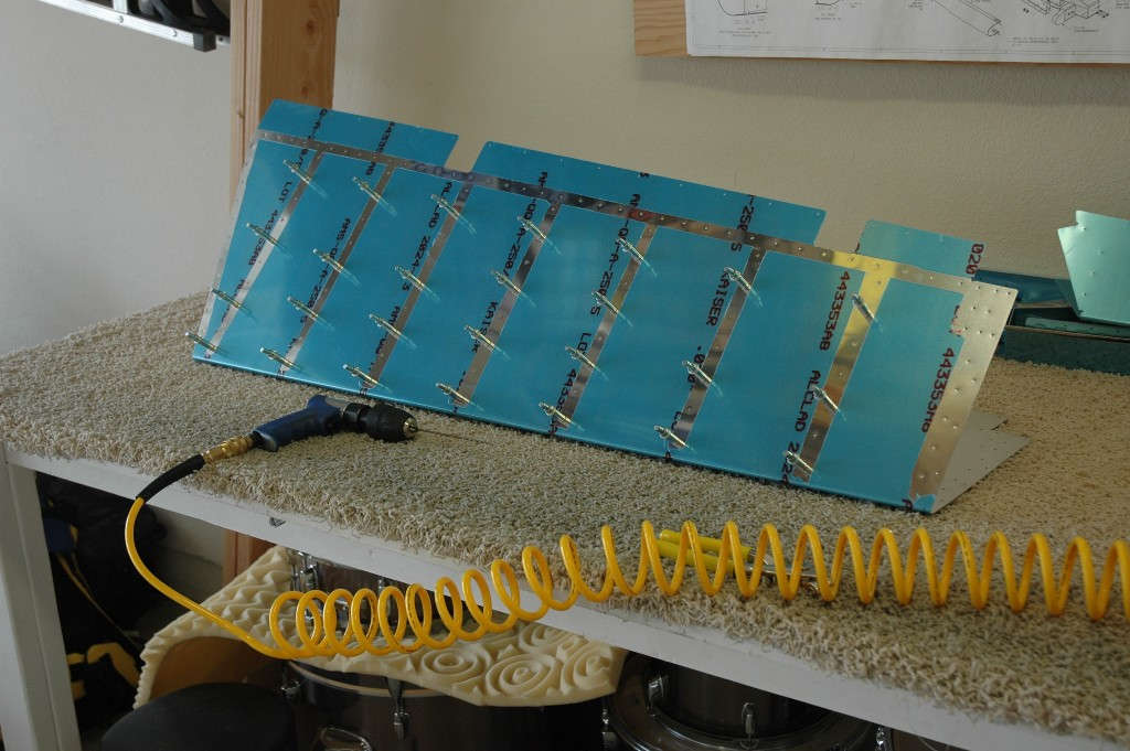
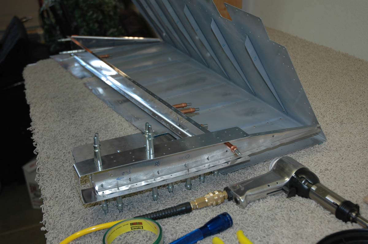
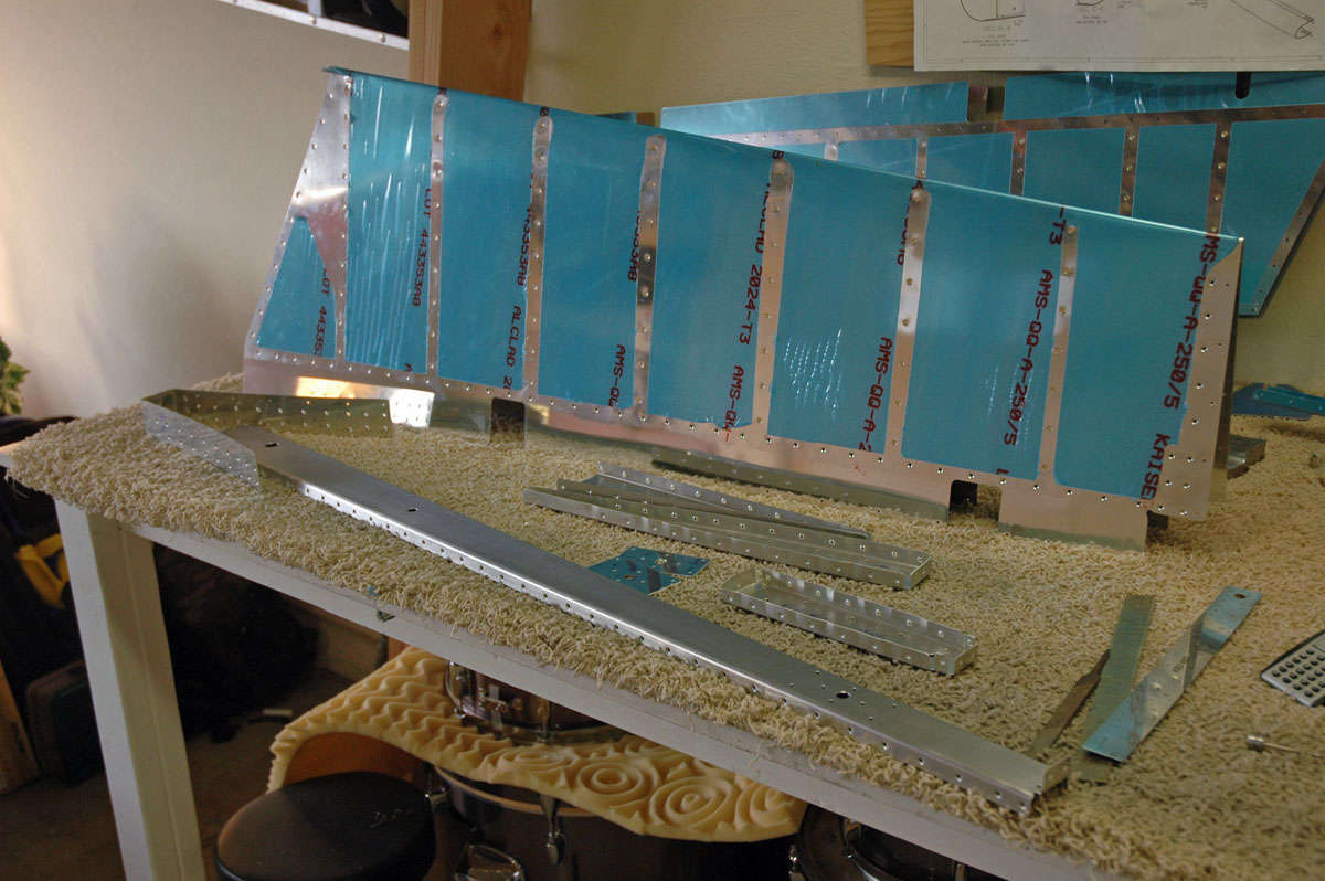
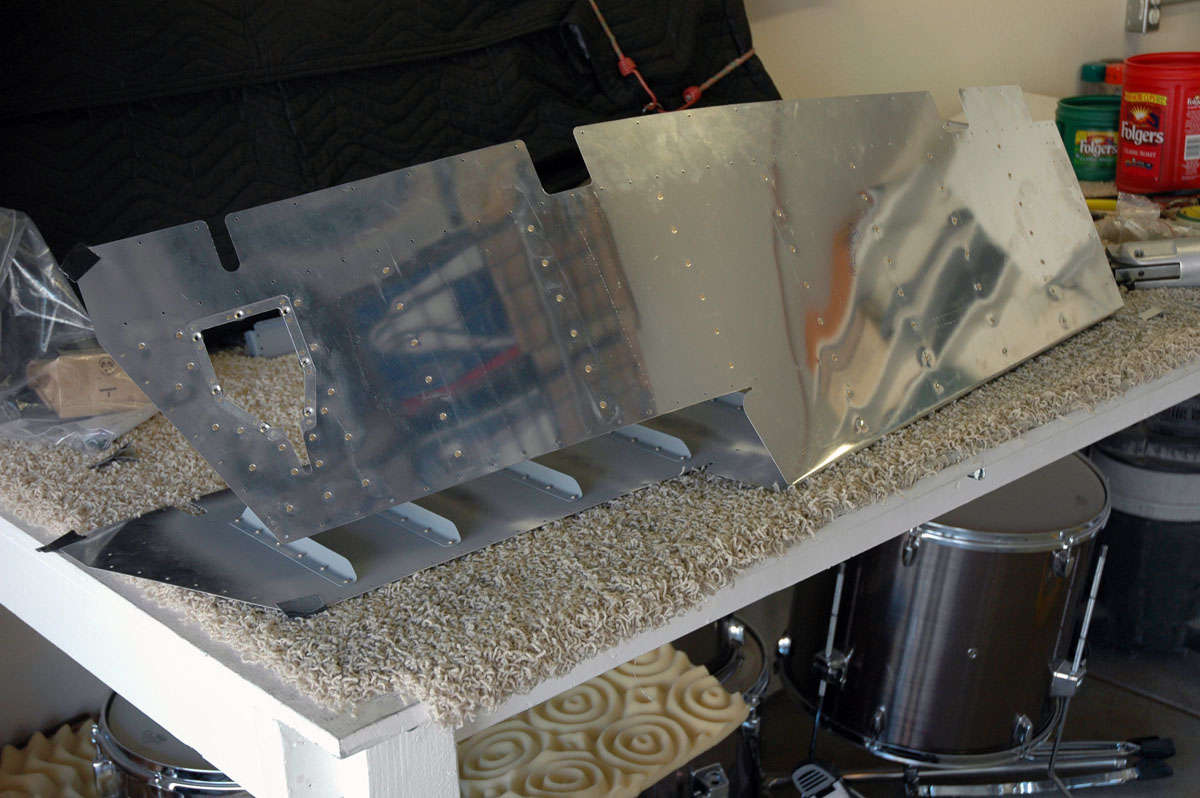
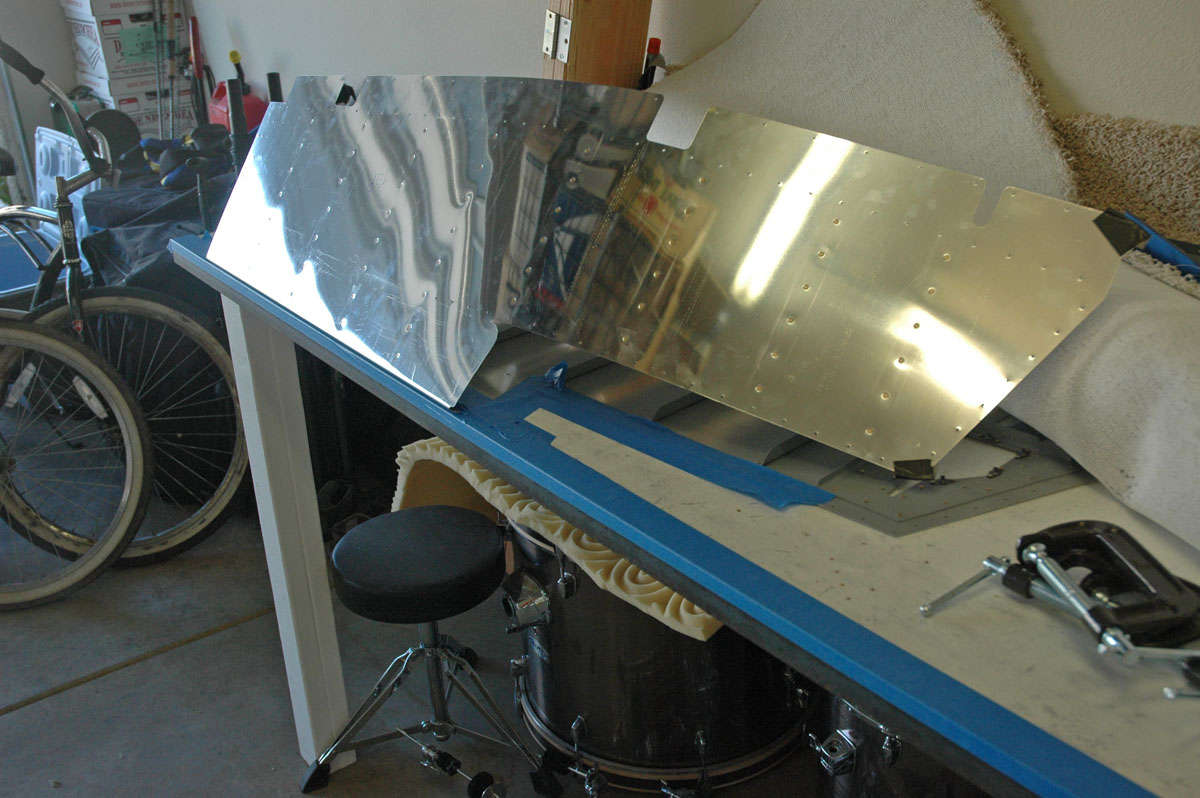
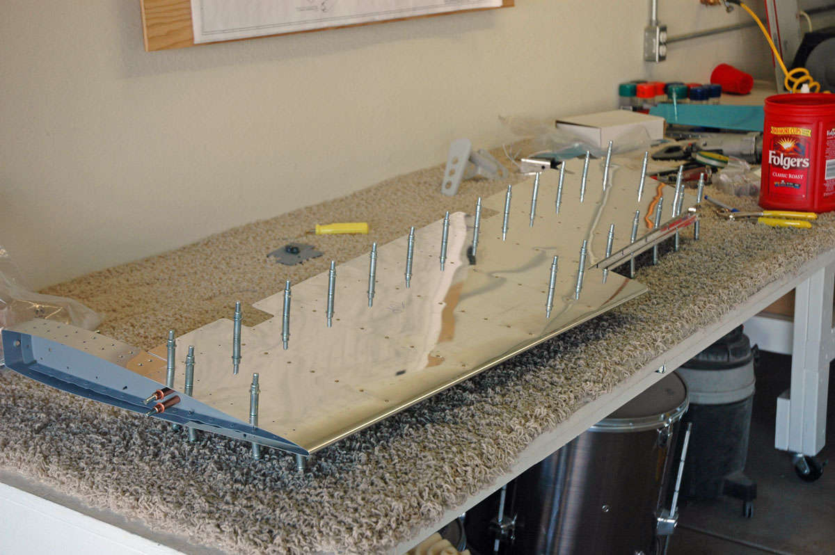
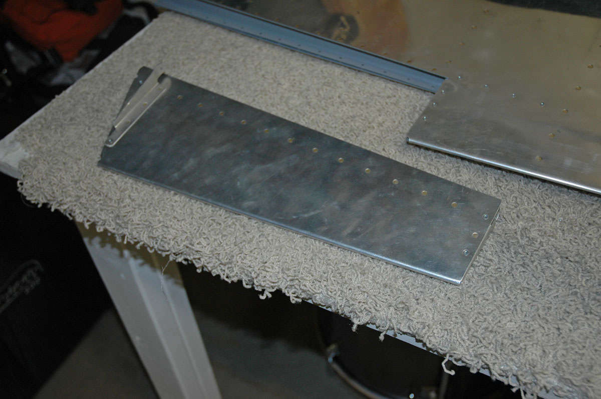
Here are the stiffeners on the work bench with most of the other elevator parts, waiting my loving attention. The box on the lower right is the electric trim actuator, an option for the airplane that I thought I should have. It is worked into the elevators during construction.
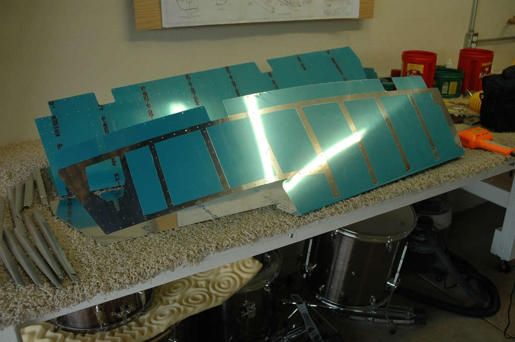
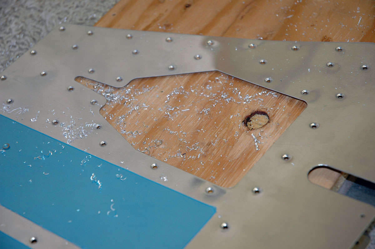
And here's another view after I trimmed the blue vinyl covering off the future rivet lines. The panel on the left side of the closest elevator skin is the panel into which the trim actuator will eventually be mounted. It is the lower surface of the left elevator. The trim tab will mount immediately aft.
Meanwhile, in the middle of all of this, the EAA Tech Counselor came by. Well, actually I went to the Lincoln Airport and picked him up on Saturday morning. He and another RV expert came by to look at my work. They both had a few helpful pointers and suggestions, but pronounced my work as sound and acceptable. One thing both mentioned is that I need to bend the rudder skin a bit better to the final fit, something I had already decided needed to be done. Something about tension on the skin and cracks at the trailing edge of the rudder. So, one of the gentlemen offered his custom set up to bend both the rudder and both elevator skins to exactly where they need to be. I'll go to his shop in a few weeks and do all three skins 'just right. I'd mention both their names but I haven't asked them permission, so I won't mention their names. Maybe next time. EAA is an invaluable resource for me and other builders like me.
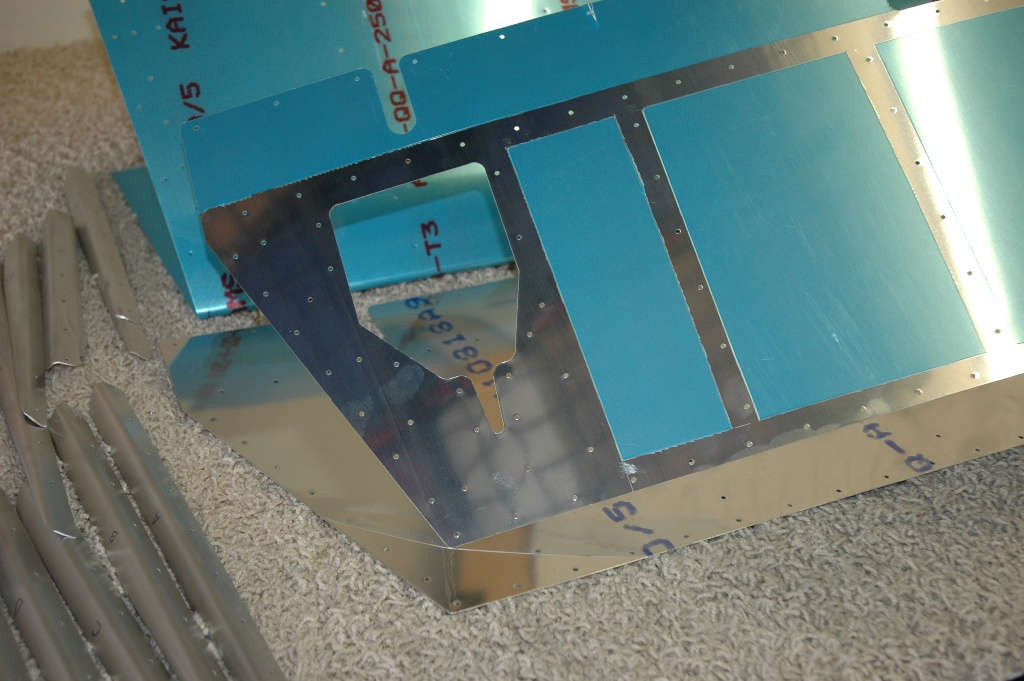
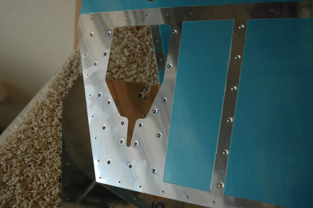
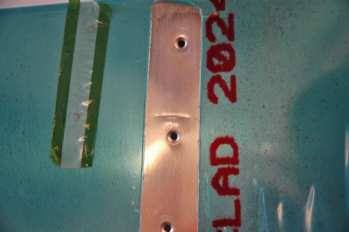
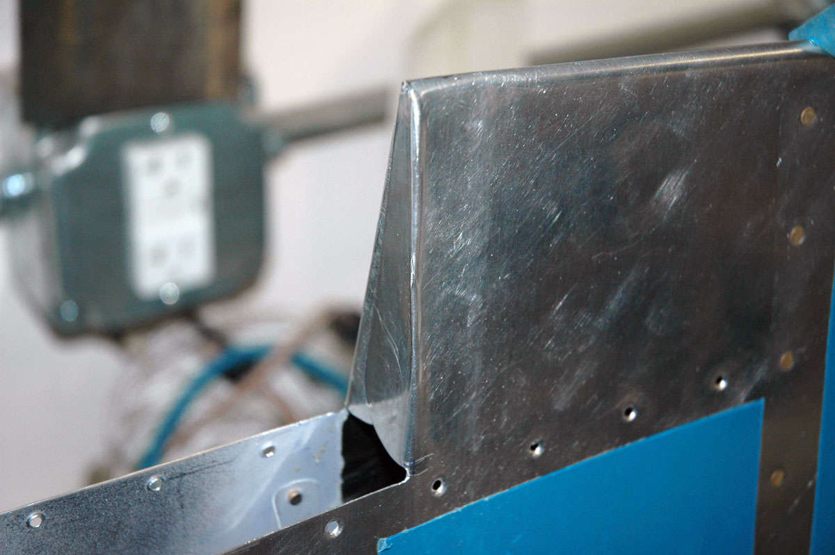
So, back to the elevators. Here is a closer view of the trim access area. A large backing plate is mounted under the skin and is fitted with nut plates. Then, a skin cover is screwed onto the backing plate as a cover, allowing access for maintenance later.
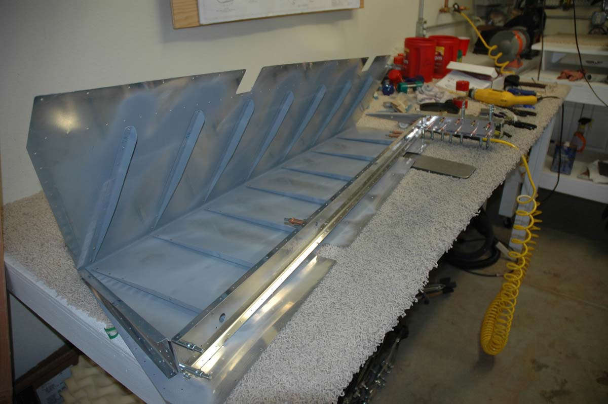
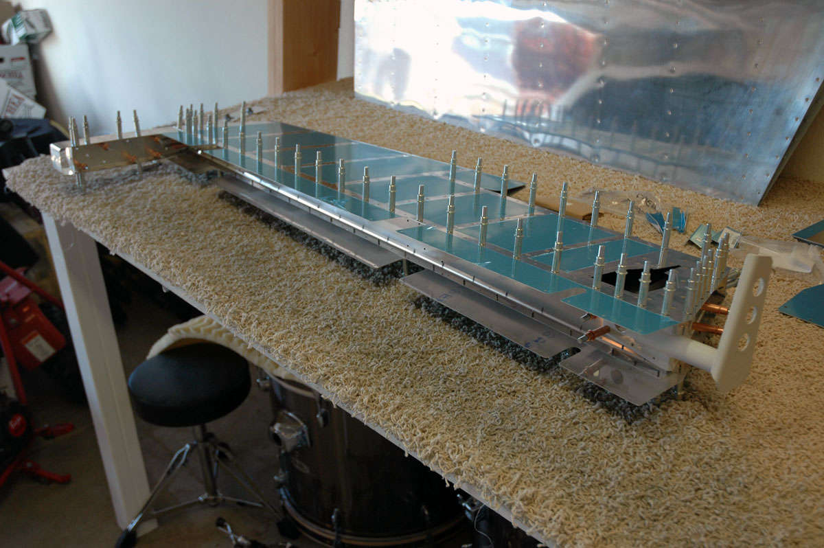
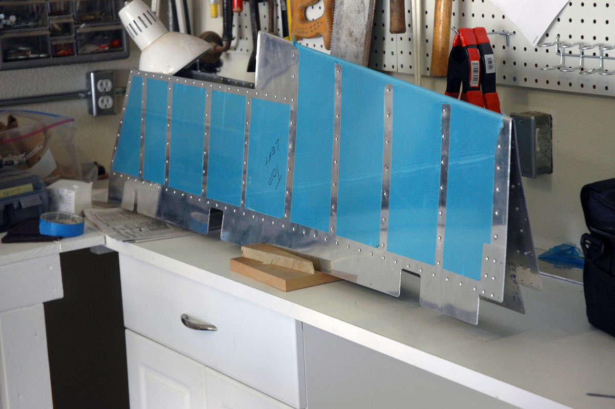
Stiffeners done, they are clecoed to the skins and match drilled. Twenty-eight stiffeners, six to nine holes per stiffener...you get the idea. But I enjoyed the drilling now because all the holes in the skin and stiffeners would have to be deburred next.
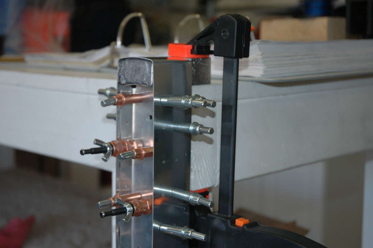
After all the holes are deburred, the skin and the stiffeners are dimpled for the later flush riveting. Here is my DRDT-2 making quick work of dimpling a stiffener. Right tools for the job....so much easier.
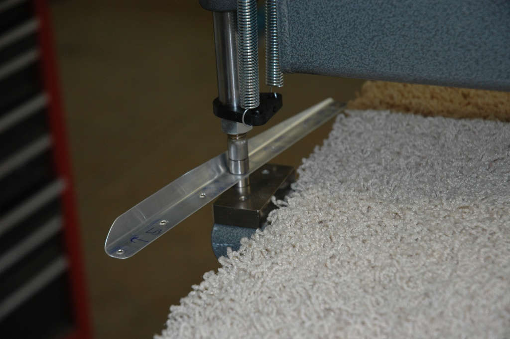
Then the skin was dimpled, mostly with the DRDT-2 but I had some problems on the rudder at the closest hole to the trailing edge, at the tight bend point. So, on the elevators I got smarter and used the Pop Rivet Dimple Die set which, amazingly, worked just fine in the tight places. Right tools for the job....so much easier.
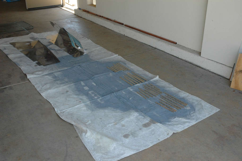
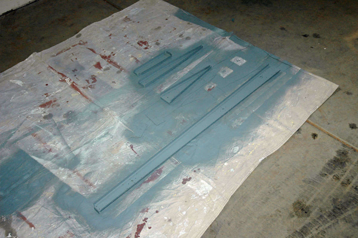
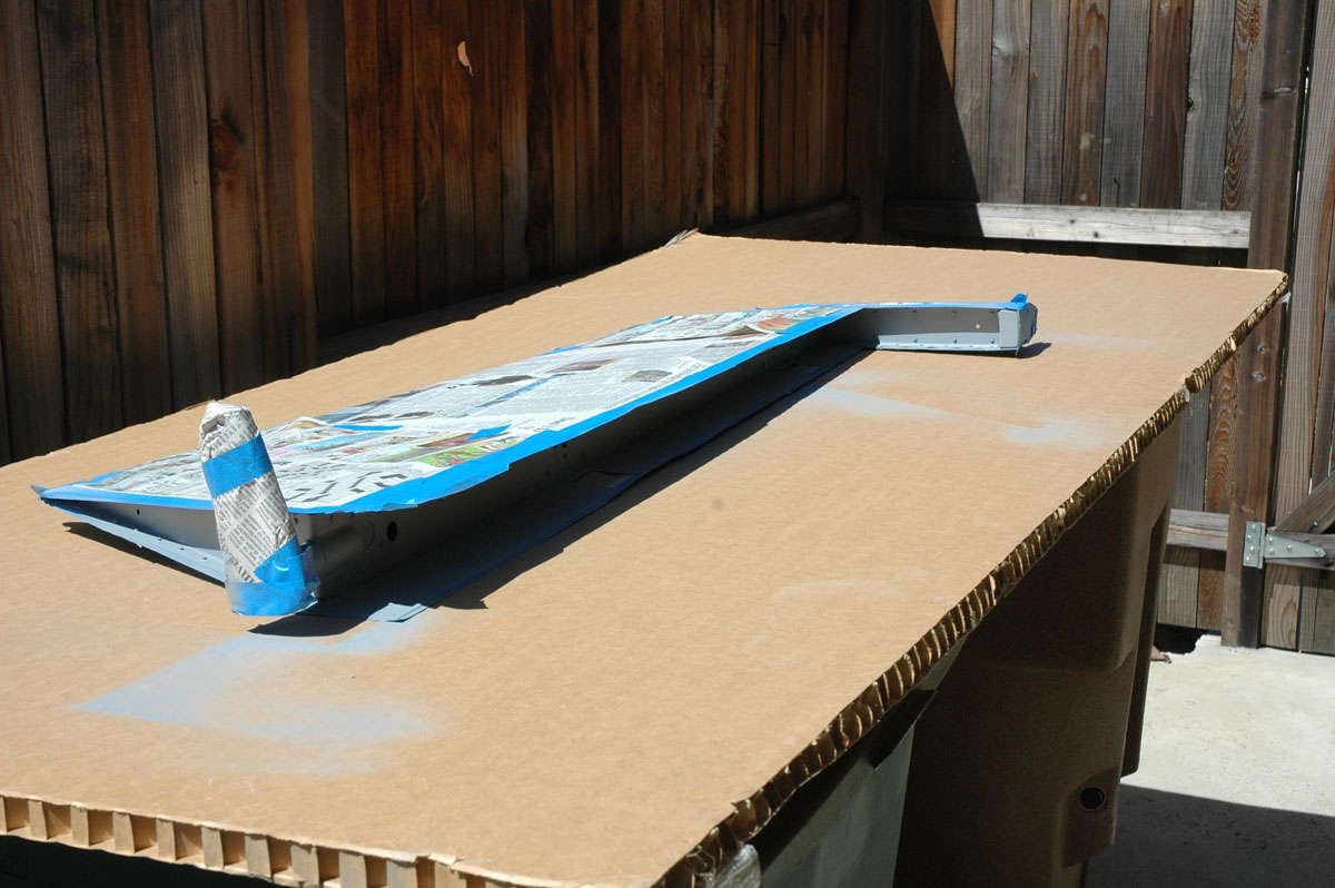
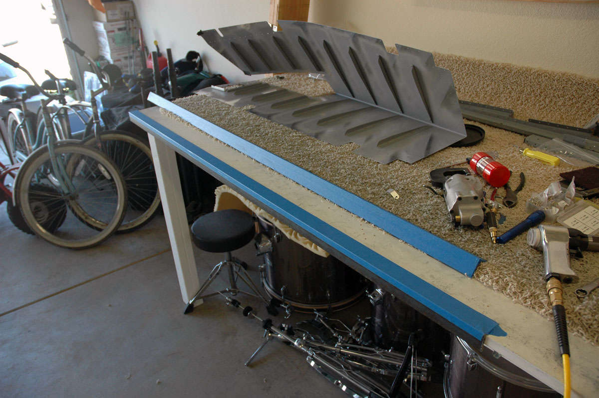
That was all done on Saturday, July 11, for the most part. Then, today, Sunday, it was off to the paint booth (garage floor) for some primer. Inside the skins where the stiffeners will go, and on the mating surface with the stiffeners, and a bit on the rest of the stiffeners just for good measure.
Then it was put it all away for a week, or maybe more. I fly this week through Thursday, then two days home before jetting off to Dallas for a week of BE300 Simulator. Might get a few hours in next Friday or Saturday, but that's doubtful. The next step is to back rivet the stiffeners to the elevator skins. Then, on to the elevator understructure.
August 3, 2009
Busy couple of weeks and no time, or little time, to do anything on this project. Spent a week in Dallas doing simulator and checkride, then flew last week around the west. Back on Thursday and got to get a little time on Saturday and today (Monday) working on the elevators. One thing I did do just before I went to Dallas was screw up the lower right elevator skin a bit. I don't even know how I did it, but I was back riveting and must have come off the back rivet plate a bit. Anyways, I put a deep gash into the skin near the trailing edge of the bottom right elevator. Only about 1/2 inch long, but deep and ugly. Not a crack, but I worried it might become one someday.
I spoke with "my" people. That included an email off to Van's and I showed the skin to my A&P buddies. Okay, they all said. Ugly but okay. Okay then, press on and not replace the whole skin. I'd like to say it won't happen again but that's probably not true.
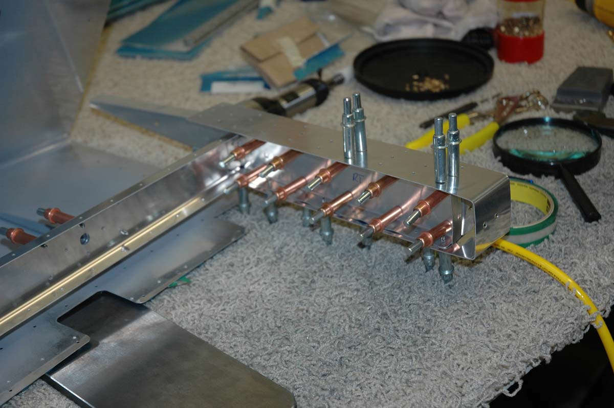
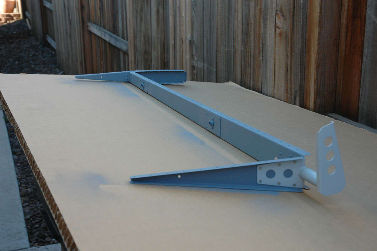
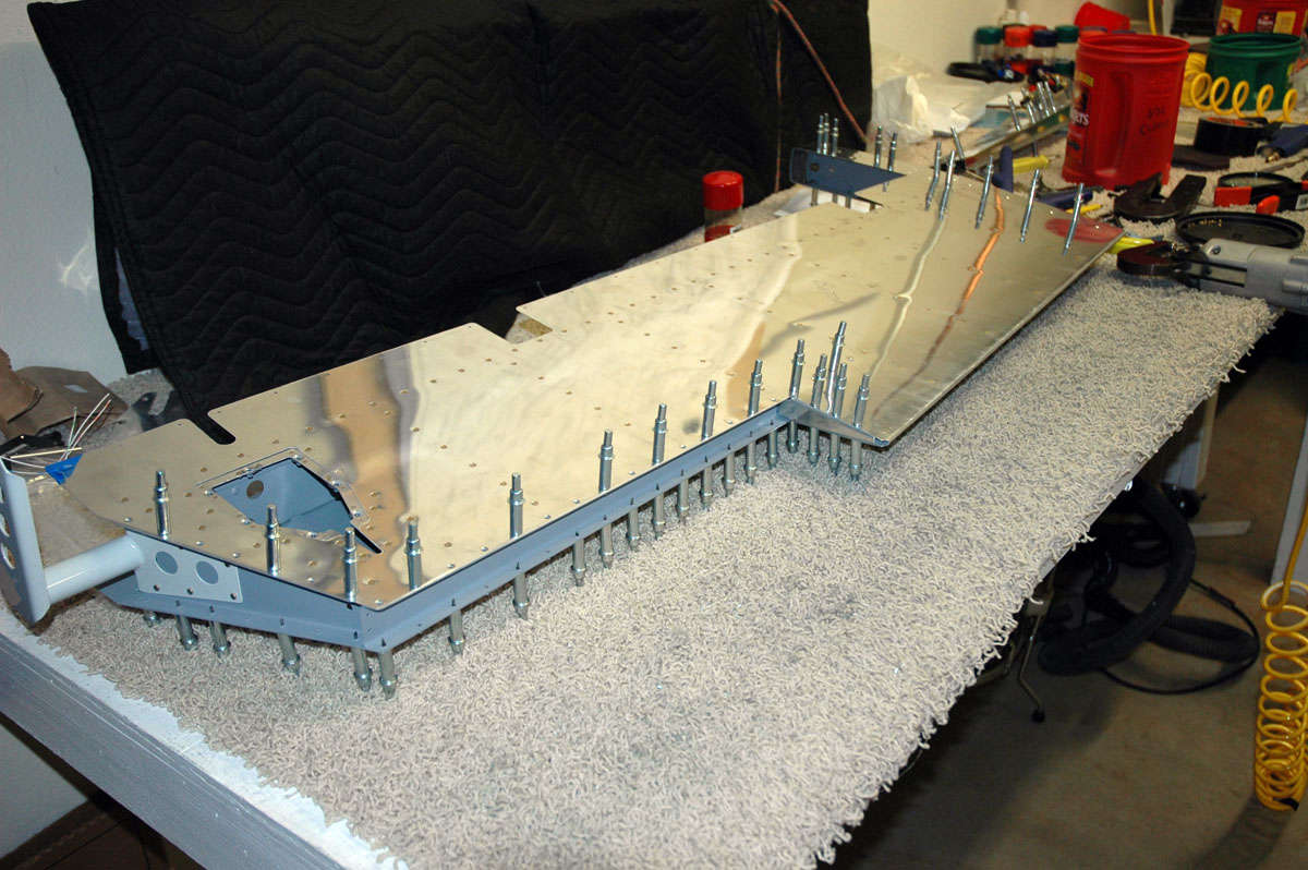
So, what I've done up to this point is finish the left elevator stiffeners (riveted into place) and about done with the right one. I assembled the right elevator substructure and worked out the counterweight frame that goes on the elevator tip forward of th hinge line. Here is the right elevator with the understructure in place.
And a look from the other end.
And here is the counterweight framework clecoed together.
Not too exciting, but I'm back in to it. Hope to get a few things done this week on the rudder and elevators. We shall see.
September 7, 2009
When last seen, I had done some work on the elevator and then jumped back to the rudder. Well, got the rudder done two weeks ago and jumped back again to continue on the right elevator. Made some good progress through these weeks. Here's pretty much where I picked up again:
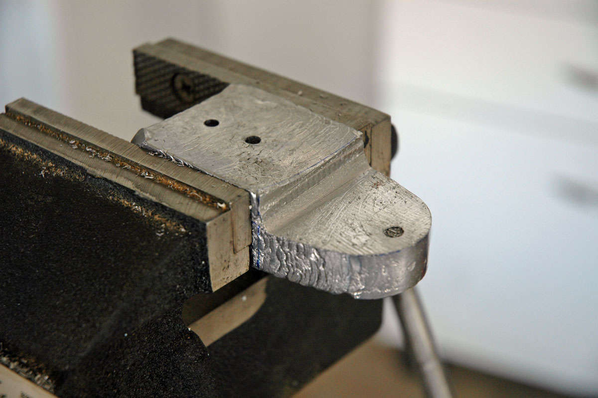
I had to do some more shaping of the lead counterweight in accordance with the plans...I had to remove a fair amount of material and did so with the magic vixen file that will also file off a fair amount of skin if one is not careful.
Later note to self, and anyone else reading this thinking they are going to learn something: trim only the counterweight for the right elevator. Not in the written instructions, and only a small note on the plans, is that the left counterweight should be left untrimmed to account for the heavy trim tab servo used for the electric trim.
After doing the match drilling of the skin and other components, using a #41 drill bit this time (keeps the rivets tighter than using the #40 as called for in the plans), I then deburred all the holes, dimpled all the skin parts, and matching understructure, and did the edge finishing and any remaining cleanup items. Then, off to the paint shop for some priming.
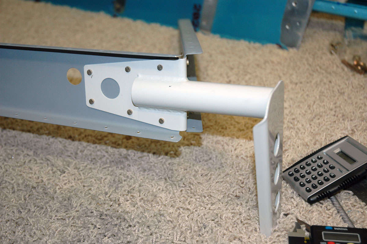
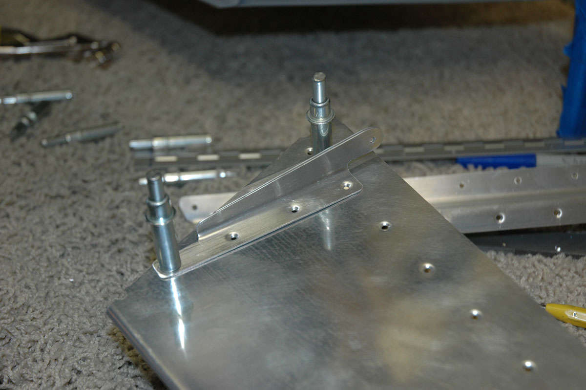
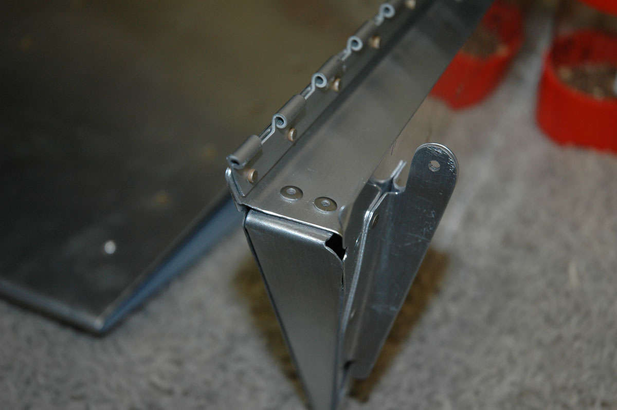
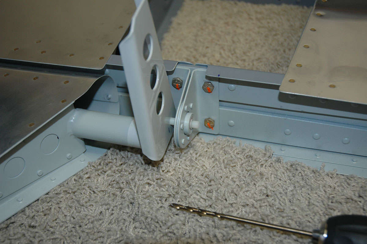
Then it was back to the assembly shop, where I started riveting the understructure together. All went fairly smoothly and quickly. Here is the elevator horn attached to the spar and the end rib. Not too shabby.
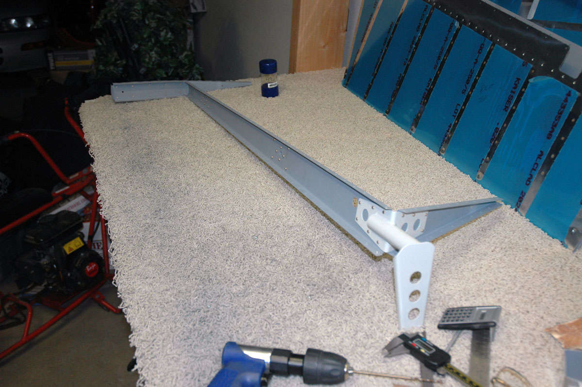
Wouldn't do without a close-up, now, would it? The spar and end rib and flush riveted together so the elevator horn will fit nicely. Once the elevator horn is attached the structure stiffens up right smartly.
Then, once the understructure is completely riveted together, it is off to the auxiliary paint shop for some primer touch up...nothing fancy but the rivet surfaces also get a touch of primer.
That all pretty much took the first weekend. I had a funny week last week, spending some time with the FAA DC-3 at Offutt AFB, Nebraska. Good show, had an unexpected opportunity to catch up with some old friends too. Got back in the early part of the week, and had a day to fiddle, er, work on the right elevator some more. Here is the skin clecoed into final position as I got ready to put the whole thing together.

All the rivets are squeezed, so it goes pretty quickly. After the rivets were set and everything looked ship shape, I decided to do a bit more touchup of the primer and add some gloss enamel to a couple of the to-be-exposed surfaces. So, back to the paint shop. Decided to use the auxiliary paint shop this time.
Then we had the challenge of the session...trying to roll the leading edges. Not sure why this gave me so much trouble this time. I think I tried to hurry it a bit and it bit me back. Scraped some skin off my fingers, too. Oh well, blood, sweat, and a few tears (actually, I didn't cry but I did get frustrated.) So, I put it away for a day before I got too frustrated and came back and worked a bit more patiently with it. Came out okay. Still seems to be more bend need than aluminum available, but I guess it turned out okay after all.
Another one of those close-up things...here working my way up the seam as I drill to size, deburr, and re-cleco and set with a pop rivet.
Okay, here's the baby good and done. Leaned up against the parts for the left elevator, the one with the (drum roll, please) Trim Tab. But before I thought about that, I took my right elevator to work for "show and tell." "Oooh...ahhhh" said everybody, but also I got one of my real mechanic guy buddies to use his little torque wrench and properly torque the counterweight nuts to the counterweight screws. Thanks be to Greg and his tiny torque wrench.
So, this past weekend, the three-dayer (i.e. Labor Day) saw me dive into the left elevator. The preparation and assembly is pretty much the same as the right elevator except for the (drum roll, please) Trim Tab. This has caused enough RV-8 builders grief that I will proceed very cautiously about the (drum roll, please) Trim Tab. However, the whole thing starts off innocently enough with the preparation of the tip and the counterweight, just like the right elevator. Here "we" are getting ready to drill the two #12 holes in the lead counterweight.
So I drilled and I clecoed and drilled some more, until at the end of Saturday I had the left elevator all final drilled and ready for the next step...deburr all the holes, dimple all the holes, edge finish all the edges, and then do some priming. Not sure if I'll use the primary paint shop or the auxiliary paint shop this time around. However, the (drum roll, please) Trim Tab has its own little spar and I mocked the trim tab up and figured how it was to mount on the elevator and pondered and thought and pondered a bit more (didn't drool) as the sun set in the west at Lincoln.
I 'figgered' I'd get back to it today on Labor Day, but I 'figgered' wrong. Too much other stuff to do....oil change, lawn care, brunch at Mimi's, thinking about the AFL-CIO, stuff like that. Didn't get back to it at all. Okay, next weekend, more work, maybe even get to the (drum roll, please) Trim Tab.
September 27, 2009
Well, here it is three weeks later. I encountered the dreaded trim tab and was defeated. I also was working on the trim tab spar, otherwise known as E-615 PP and oversunk the counter...so all in all it was not a good time. But, I have staggered along and gave Van's a bit more of my money and am proceeding a bit wiser for the experience.
First off, I was working on the E-615PP trim tab spar. All was proceeding smoothly. The bottom of this piece is dimpled to match the lower elevator. The upper surface, where it mates to the upper skin, needs to be countersunk to allow a smooth lower surface of the flange, to which the trim tab hinge will be riveted. Okay, dimpled just fine, then got out some scrap the same thickness as the spar and drilled some #40 holes into it. Set up the whole deal and carefully adjusted the countersink so the process would not make the countersinks too large, thus enlargening the holes. Tried it out, worked fine. Set up the real deal piece, drilled through each hole to allow the countersink tool to do its work. Confidently countersunk each of the holes on the upper flange.
Pulled it off the table. All the holes were enlarged. I had sunk them too deep. Hmmm. Well, I didn't actually say "Hmmm" but that was the idea. I scratched my head and thought about it. This piece is sandwiched in between the top skin and the trim tab hinge, which almost acts as a doubler. Would it be okay? Did some forum diving for awhile...some said it was okay in the process. In the end, I decided to pop for the $9 plus shipping and redo the part. Okay. Not the best example of how to set up work.
So, moving on from that mini debacle, I cleaned and primed all the parts of the interior structure (less the trim tab spar) and the inner skin. Waited a week to dive back in.
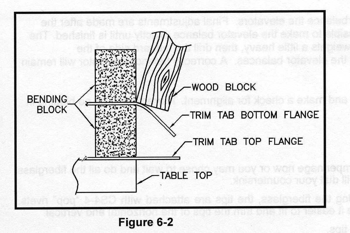
A week later, I dove back in. With both feet. Now, other guys have had fits with the little endplate in the trim tab opening on the left elevator. Van's designed this with two tabs that are bent 90 degrees and then riveted to cover the opening. The problem is, you get one chance at the bends. Screw it up badly enough and the skin is toast. The instructions are a bit hazy but I set the thing up as directed, after doing some more forum diving.
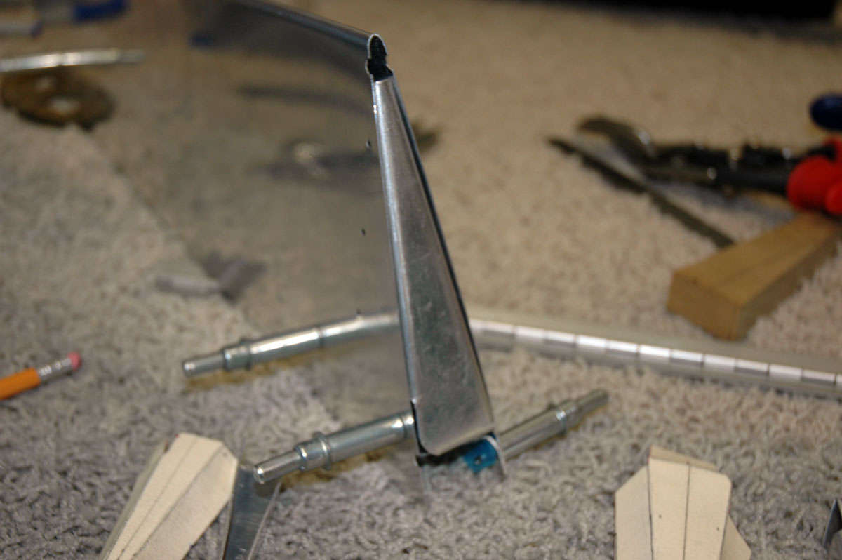
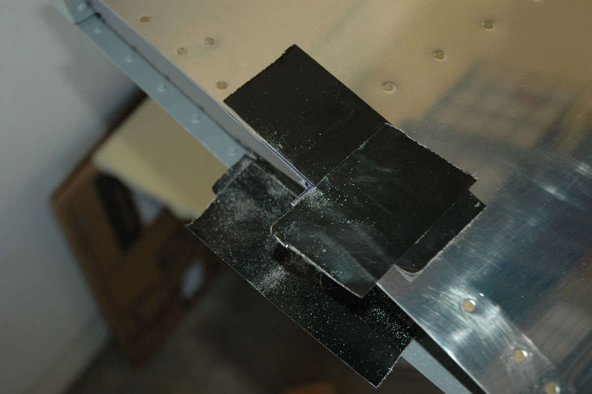
Okay, then. Started the process and bent the first tab. Used the rivet gun with the flush set mounted to run up and down the tab to crisply set the edge. The results were not great; the bend line was correct as far as I could tell but it left too much of the tab for the other tab to bend over very well. So I had to do some trimming on the bent tab. Frustration level went from Green to Yellow. So, after trimming the first tab, I carefully bent the second tab down and over it. Okay, not great again, but acceptable. Used the rivet gun to make the edge crisp. Looked okay; not great, but okay. Frustration level went from Yellow to Orange. I can make it better, right? Crisp that baby right up. Ran the rivet gun up and down the highway and got lost. Problem 1: the edge cracked. Problem 2: the wood I had set in to make the bends shifted or whatever, but the edge ended up crimped. Frustration level blew from Orange, right through Red, and into the Infrared zone. I stood there and couldn't believe it. Wrecked that whole skin with a little "I can make it better." I'd like to say I took more photos but as the frustration level rose my desire to document my screw-ups diminished. But just for posterity's sake, here are two of my completed handiwork:
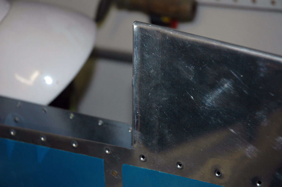
The photos don't do the screw-up justice. It was not salvageable for even crappy work.
I put the whole thing away, totally disgusted with myself and with the left elevator. Bummer.
The next day, after licking my wounds, I decided that all I could do was order a new elevator skin and rebuild the thing. Bummer. Ordered another skin ($65 plus shipping) and started taking my old elevator apart. Drilled out a bunch of rivets. I'm getting good at that.
Went off to fly the DC-3 again...this time to an airshow at Scott AFB in Illinois. No RV-8s or any RVs present at the show. No WWII warbirds save a lone P-51. Some good flying by the USAF and USN guys, and a good show for the RCAF Snowbirds. At least on Saturday; Sunday it rained and the flying was cancelled.
Back to Lincoln, and what should be awaiting me is a new, virgin, E-615PP spar and new, virgin, left elevator skin. So, lets see what I can do with these. Did he learn from his mistakes? Well, I had already decided this "bend the tabs" idea wasn't going to fly for me. I had done some forum diving and found that guys had made little "riblets" for both the elevator and the trim tab itself (which also has some bendy tabs). Okay, sounds good. Make some riblets and remove the "one chance" bend idea.
So, this past week, I did all the prep work on the skin. Dimpled and deburred, edge finished and back riveted. Went quickly, almost like I had done it before.
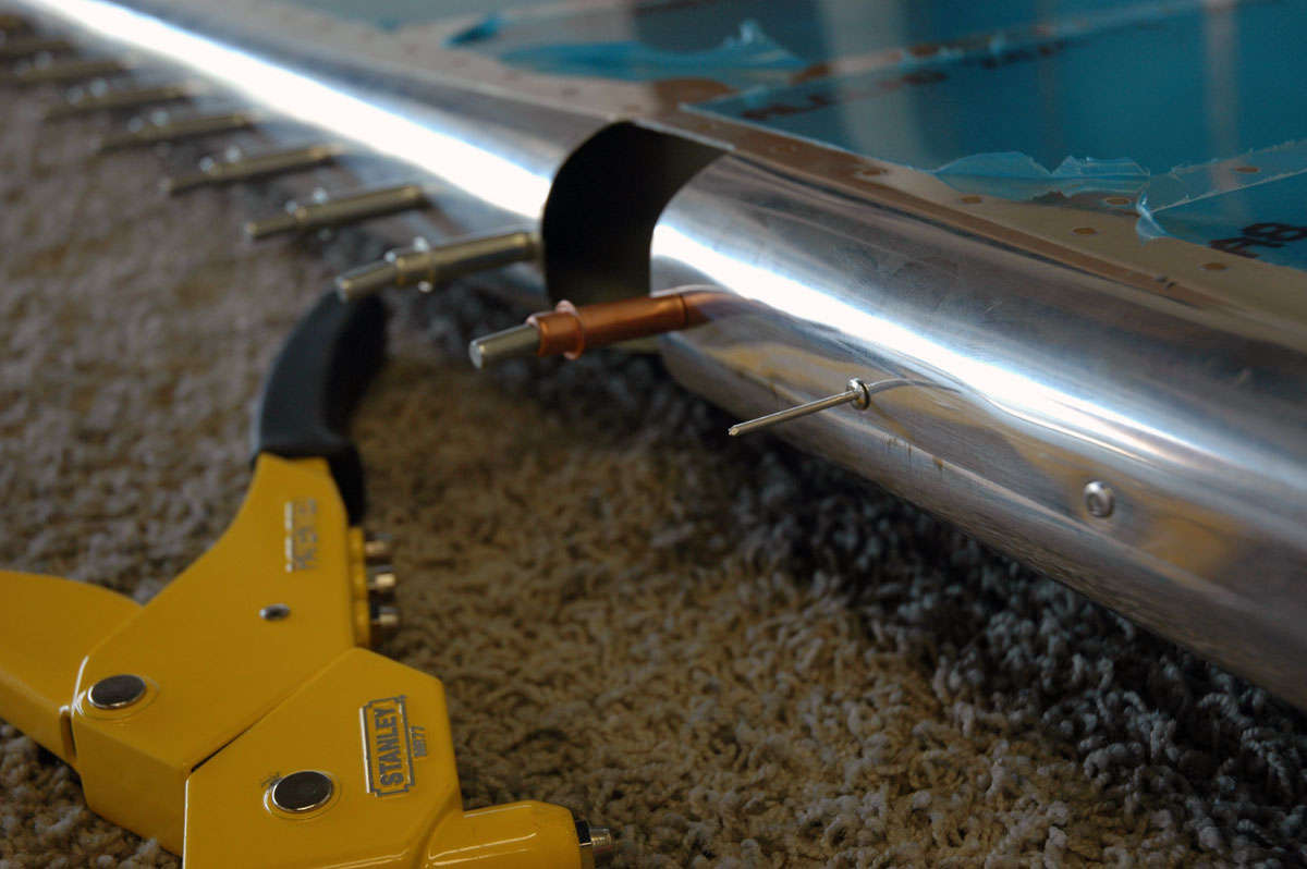
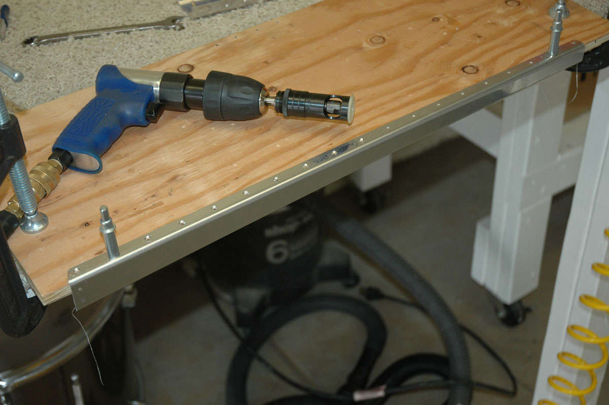
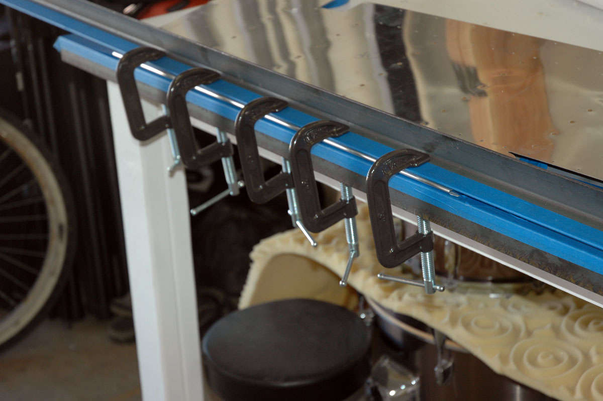
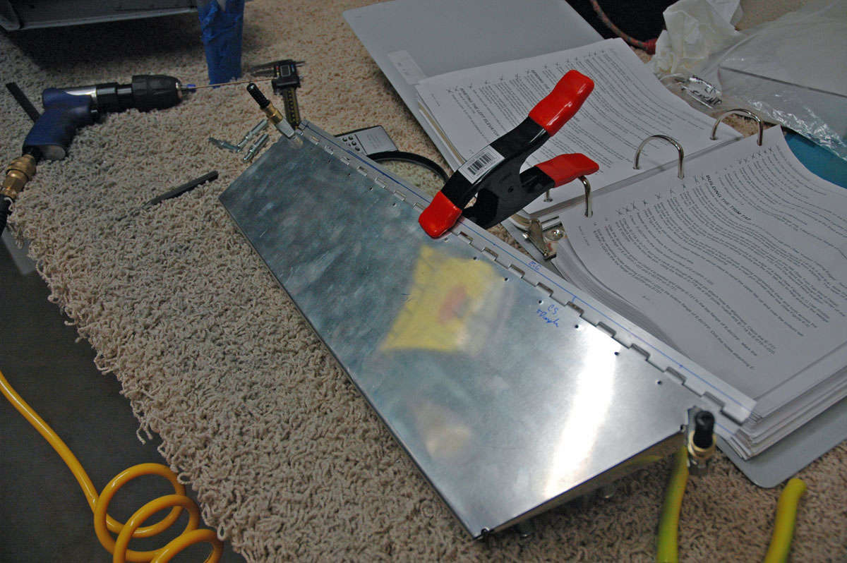
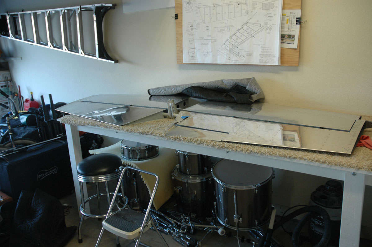
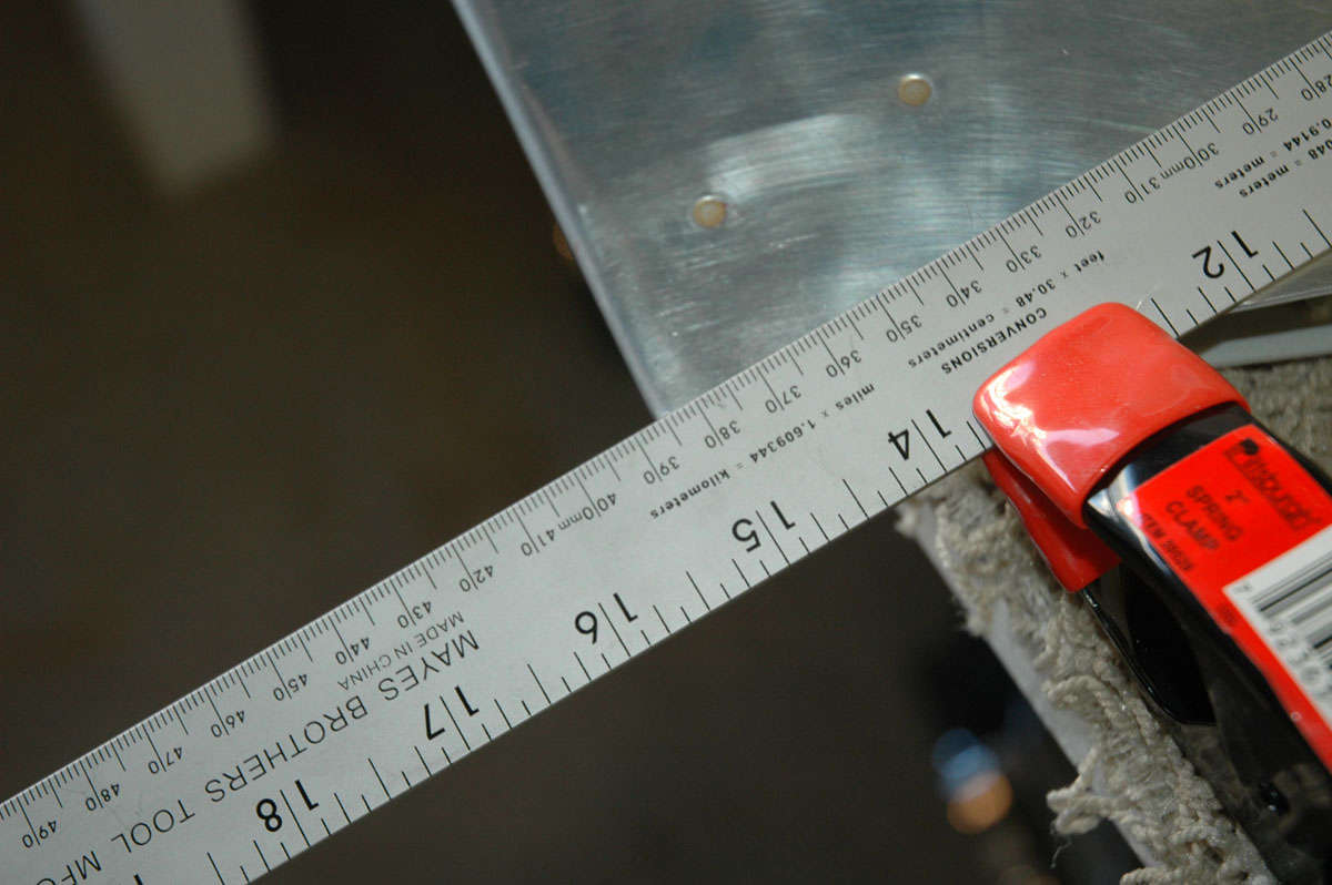
The fly in the ointment looming on the horizon was that I would have to do the trailing edge bend again. As dedicated reader(s) know, I had originally used the Van's bending brake design the first time around. Didn't work so well. Keith Peterson, an experienced RV guy, had offered to bend my edges at his shop at Grass Valley airport, and his way worked much better. So, instead of calling on Keith again, and knowing that someday I will have to bend ailerons and flaps, I set myself up with the same setup that Keith used. (That's the Van's bending brake in the background; not good for much.)
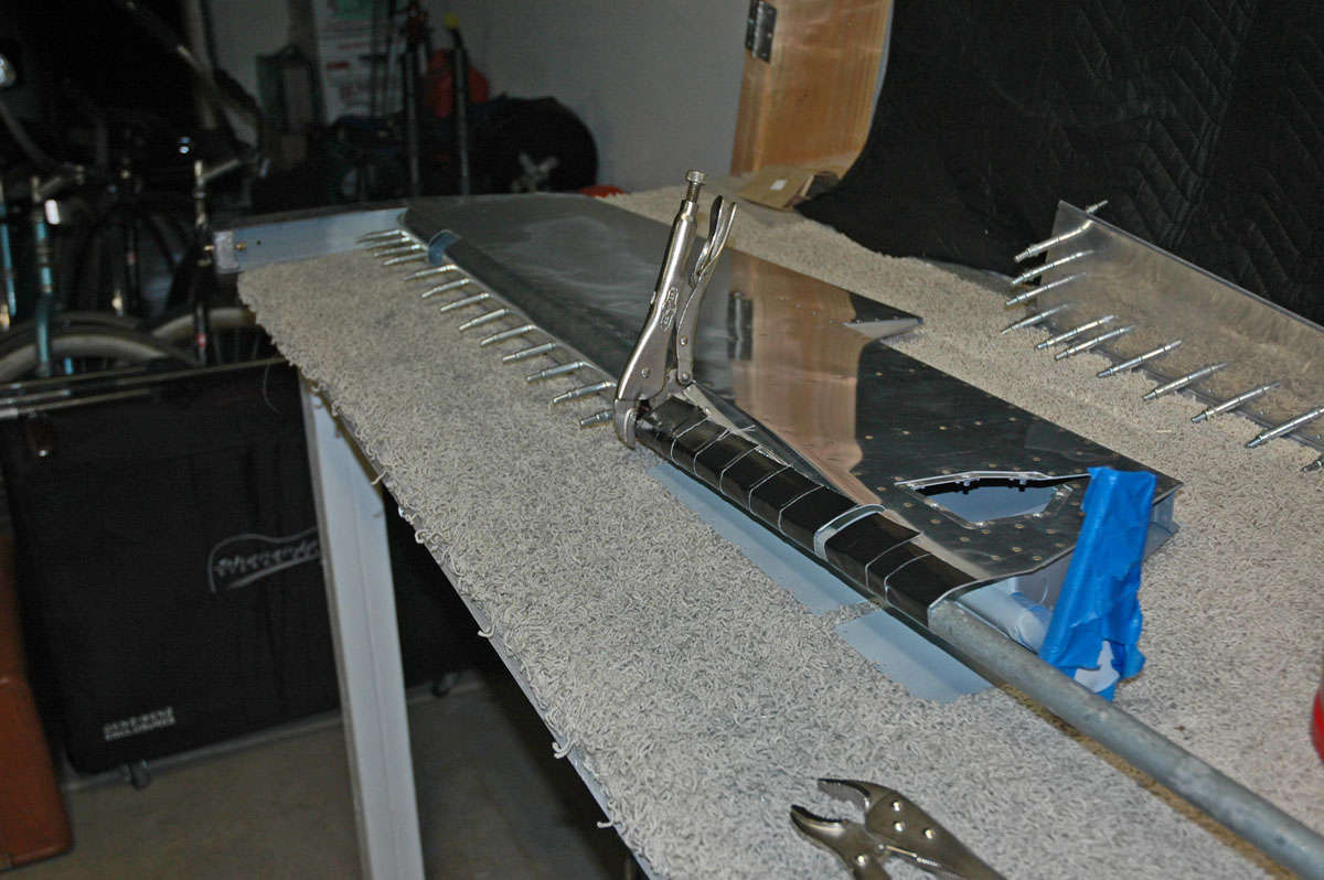
This bending method entails the use of two pieces of angle iron. One is mounted to the workbench with screws. After the skin is firmly taped into place to eliminate it shifting, the second piece of angle iron is clamped over the bend line and the clamps are slowly adjusted to make the bend.
I bent until the edge distance was about 1/4" or so, as I could remember what Keith had bent to. I experimented a bit, took it apart twice to ensure I didn't overbend. This is another thing you don't get chance #2 with: if you overbend you can drive the stiffeners into the other side of the skin and maybe even crush the trailing edge. Don't want to do that.
But it worked out great and the trailing edge is as straight as a baby's ruler.
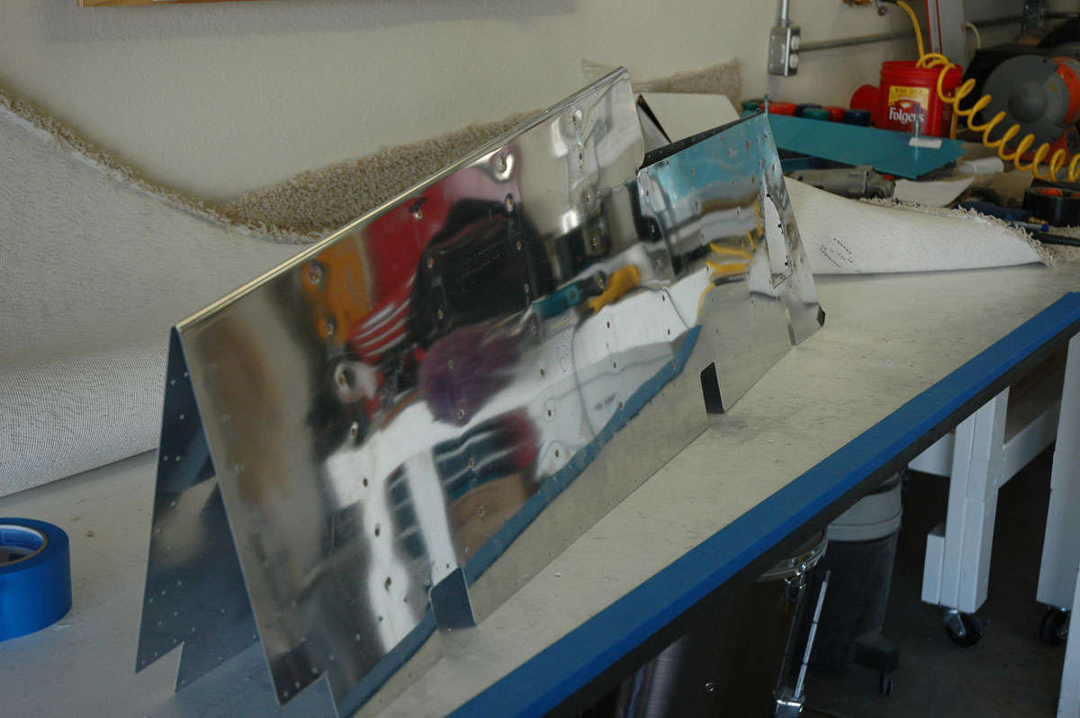
As I was doing this, I would glance over to the old skin, looking back forlornly from the other workbench. "Too bad" I would say to it, "you had your chance." I consider it a traitor to the cause, and won't talk to it anymore. It apparently isn't talking to me anymore either.
So, I reassembled the elevator again to make sure everything still fit, and also to fit in the E-615PP trim tab spar.
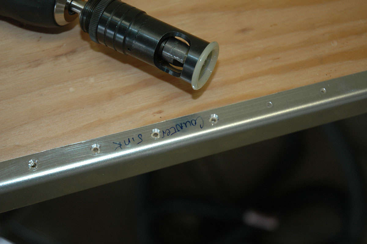
I took great pains to set the counter sink, practiced numerous time, measured many more, and then did the final drilling. Took it out, found it to be a bit shallow. Adjust a quarter turn on the countersink tool and redrilled. Okay then, fits good and works just fine. Primed that part and set it aside.
So, while the elevator was in front of me, I designed my little elevator riblet. Measured and cut, used paper first, made a couple of adjustments, and then mocked up the part with my mock-up stock (cut up manila folder).
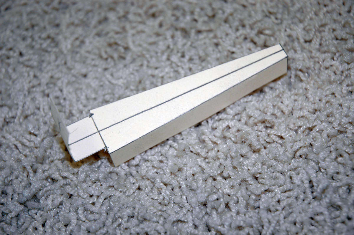
Looks good. I felt like what Ed Wells must have felt like when he designed the Boeing B-17. This should work. Just turn it into metal. How hard could that be? Next time, we shall find out.
Oh, yeah, and I ordered the wings. Should arrive in early December. This has all the makings of really building an airplane.
October 4, 2009
Good week behind me. Got a chance to spend two long sessions on the left elevator, and made a few changes to what Van's wants done with the elevator and trim tab edges.
As noted last time, the bent tabs sealing up both the elevator and trim tab edges seemed less than ideal. Lot's of guys have done this part without problems, but more guys have seemed to have had problems making it work right and look right. So since I had some major problems with the elevator here, in fact causing me to redo the skin for the left elevator, I tried an approach used elsewhere: make some riblets to replace the bent tabs. So I made some templates, as noted last time, then built one little riblet myself and had some help with two others (thanks, Greg!).

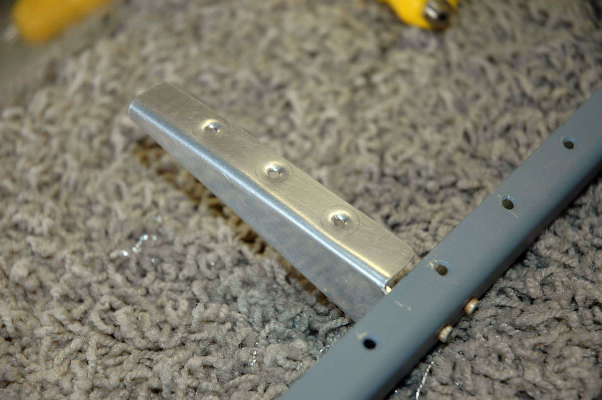
These will fit into the openings and I'll use some MK319BS rivets, otherwise known as pop rivets, to secure them. Here is the inside trim tab riblet fitted into place:
Like I said, I think it is a cleaner installation. And here is the little riblet drilled and dimpled and riveted onto the trim tab spar.
So, after that was assembled and primed, I was basically ready to rivet (again) the left elevator. All the rivets are squeezed using the pneumatic squeezer, and all but a few are AN426AD3-3.5 rivets so it moves right along. Turned out pretty well. I worked up and down the rows of rivets pretty quickly and I thought to myself this is going too easily. Just then I mucked one up and had to drill it out. Says something about the power of suggestion.
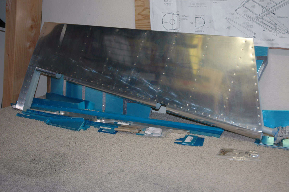
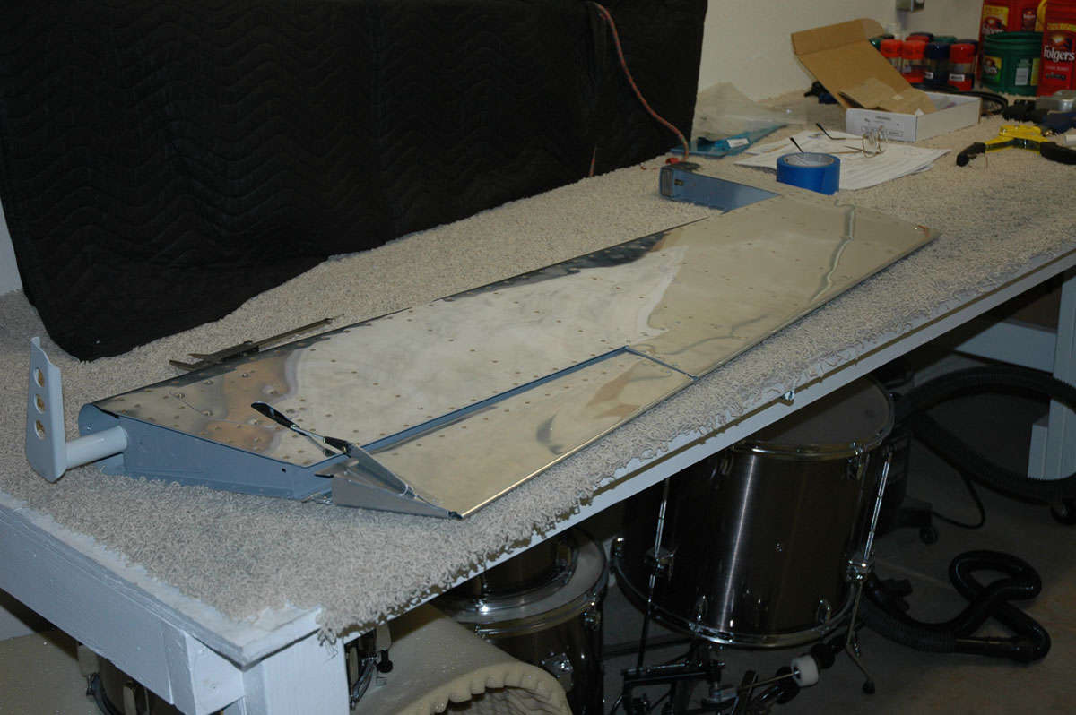
So, here is the left elevator pretty well done (need a few more pop rivets and I need to bend the leading edge) laid out next to the trim tab, in progress. I spent much time making sure the trim tab will fit properly. One advantage of doing the trim tab with riblets is that you are not committed to the width of the tab until the end. You can adjust the left edge of the tab so it gives at least 3/32 inch or greater gap between the elevator and the tab in controlled situation. Just trim a bit more as needed until the edge is right, and then mount the riblet.
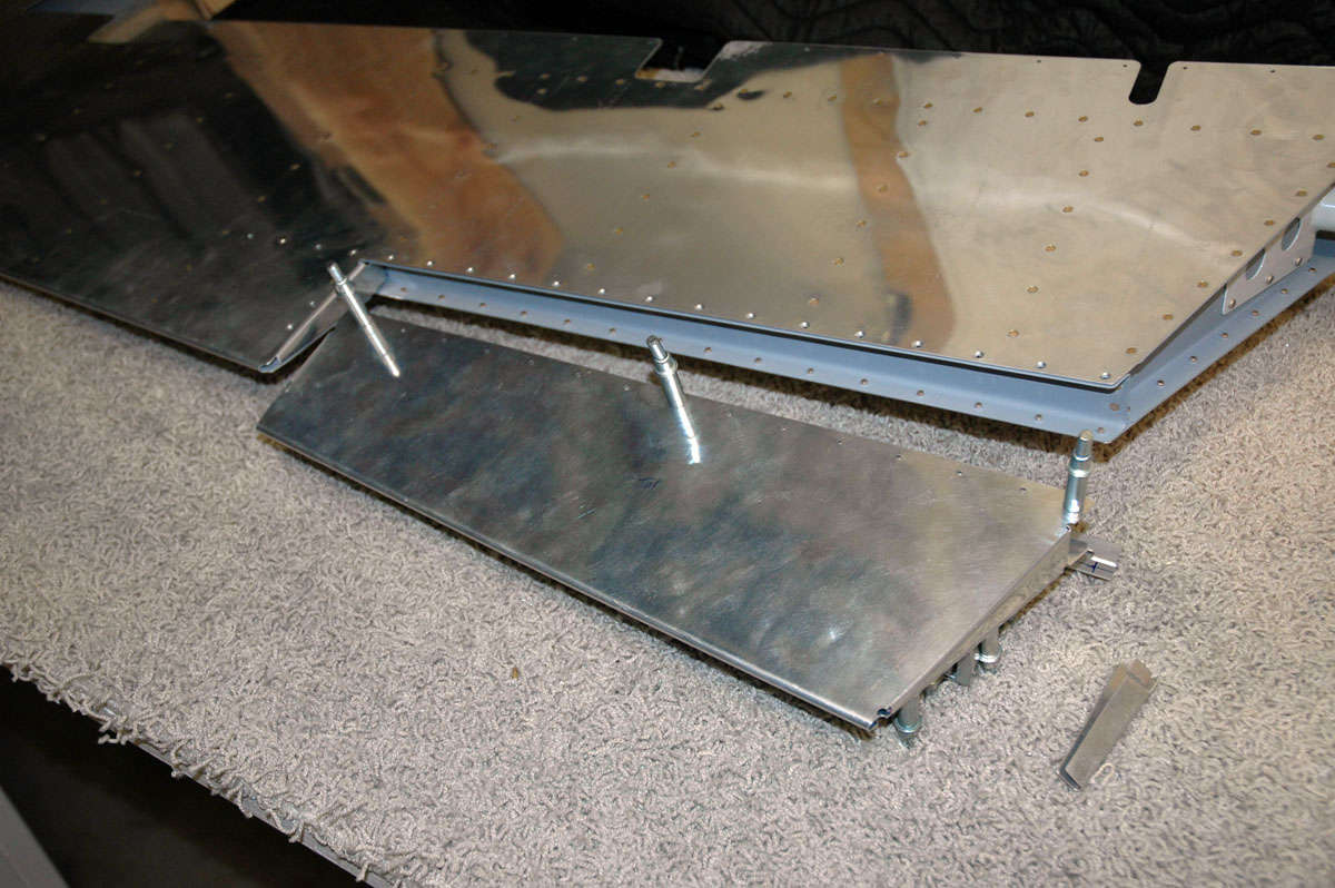
And, another view from the other side.Note that the rivets on the top of the trim tab spar are done in conjunction with riveting the trim tab hinge into place, thus they have not yet been done here.
I have the trim tab mocked up pretty well where the bottom plates are mounted to attach to the servo, but forgot to take a photo. Hopefully, this coming week will allow me to: 1) roll the leading edge (not looking forward to that); 2) complete and mount the trim tab; and 3) install the servo and associated stuff. Basically, finish the left elevator. By the way, the measurements on the plans for installing the servo on the inspection plate are wrong! wrong! wrong! so a word to the wise: get it all laid out for real before mounting the servo on the plate. I could tell right off the bat that if I followed the plans the servo would not line up properly with the trim tab.
Saturday was the Lincoln Air Show so I took a bit of time away from the elevator to run out to the airport for an hour or so, hoping to see an RV-8 or two. Glad I did, as Mike Terpstra and his son and his RV-8, N184MT, were there. Beautiful airplane and equipped like I hope mine will be someday: 180 hp injected with constant speed Hartzell; fairly basic panel and lean interior. Same sort of paint, also, in that I am drifting away from polished aluminum and toward aluminized paint. Mike finished this airplane two years ago after taking five years to build it. Based at the Modesto airport. Nice guy, beautiful airplane; what else can be said?
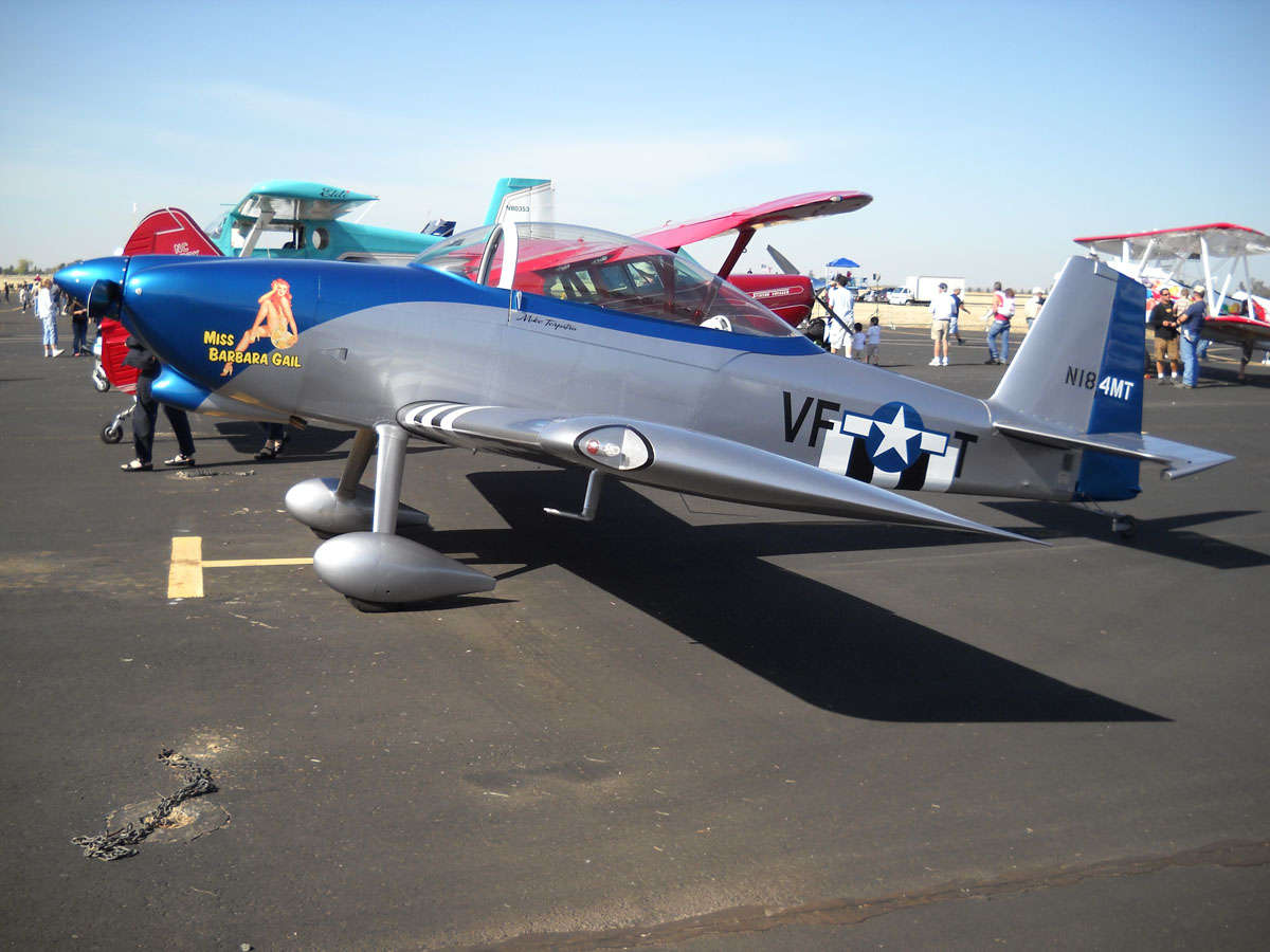
Maybe I'll make the Lincoln Air Show in 2014 with my RV-8.
Note for reader(s). I added an RV-8 area to my Aero Vintage Books Forum page if anyone wants to make comments or add feedback, etc.
October 19, 2009
Well, it's two week later. I spent a good deal of time working and didn't want to take the time to update my little website here. But off I went to Denver for my work, so now would be a good time to catch myself up. When I wrapped up my sessions in early October I had pretty well riveted it together, all but a couple of hard to reach rivets and the hinge that attaches it to the elevator.
So, here is where I picked up week before last, lining up the hinge and trial fitting it.
I did all the prep work and drilling to fit the trim tab control horn into position. It is actually two parts that are riveted into position as one part.
I riveted most of the trim tab together and then set it aside to get some advice on some hard to reach rivets; the question: pop or agonize over how to get in and set them with a rivet gun.
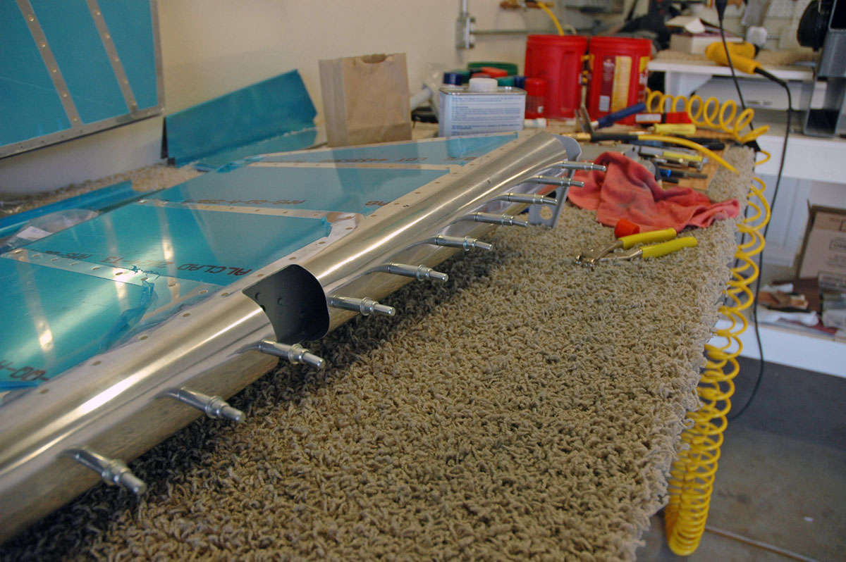
So, cogitating over that, I moved on to roll the leading edges of the left elevator. Took a tip from another site: roll the thing in sections. I did that and it proved to be a bit easier. Still not great...there seems to be more curve than skin, but I guess that is the way it is supposed to be. Here is my pipe and my Gorilla tape at work.
So here it is coming together, the trim tab clecoed in place with the hinge in a final fit, and also the control horn in position.
So I then turned my attention to the trim tab servo that mounts on the access plate that fits on the bottom of the elevator. As noted at the end of my last entry, the plans are wrong as far as setting up the servo mounts. If you follow the plans, the opening for the servo does not line up with the trim tab horn...not even close. So I set it up in real time and still had to adjust the horn a bit to make things fit correctly.
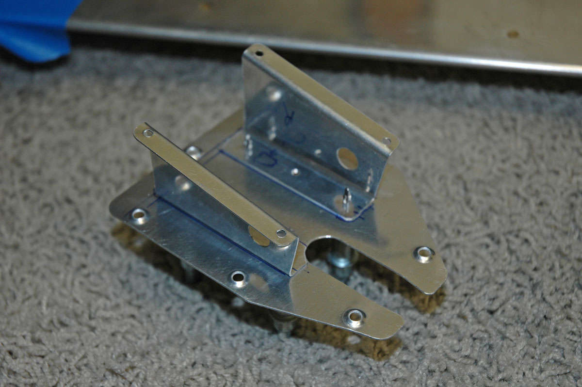
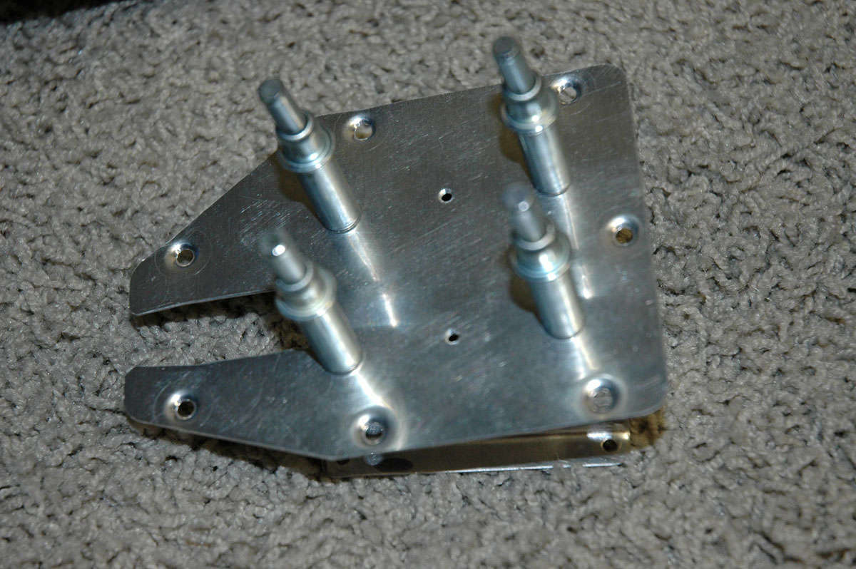
So, here is the other side of the access plate with the servo mounts clecoed. Good to go.
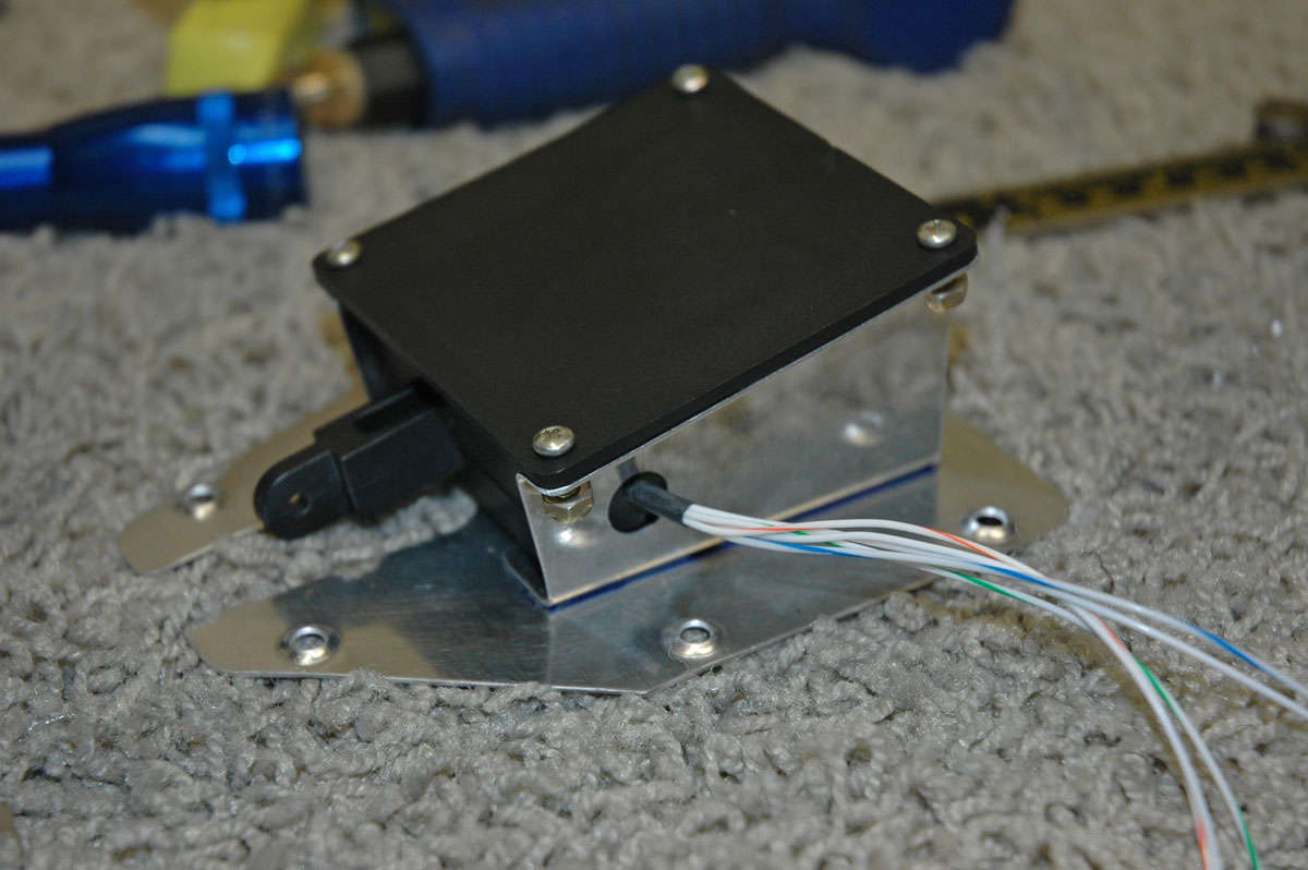
And, here is the servo test fitted in the mount.
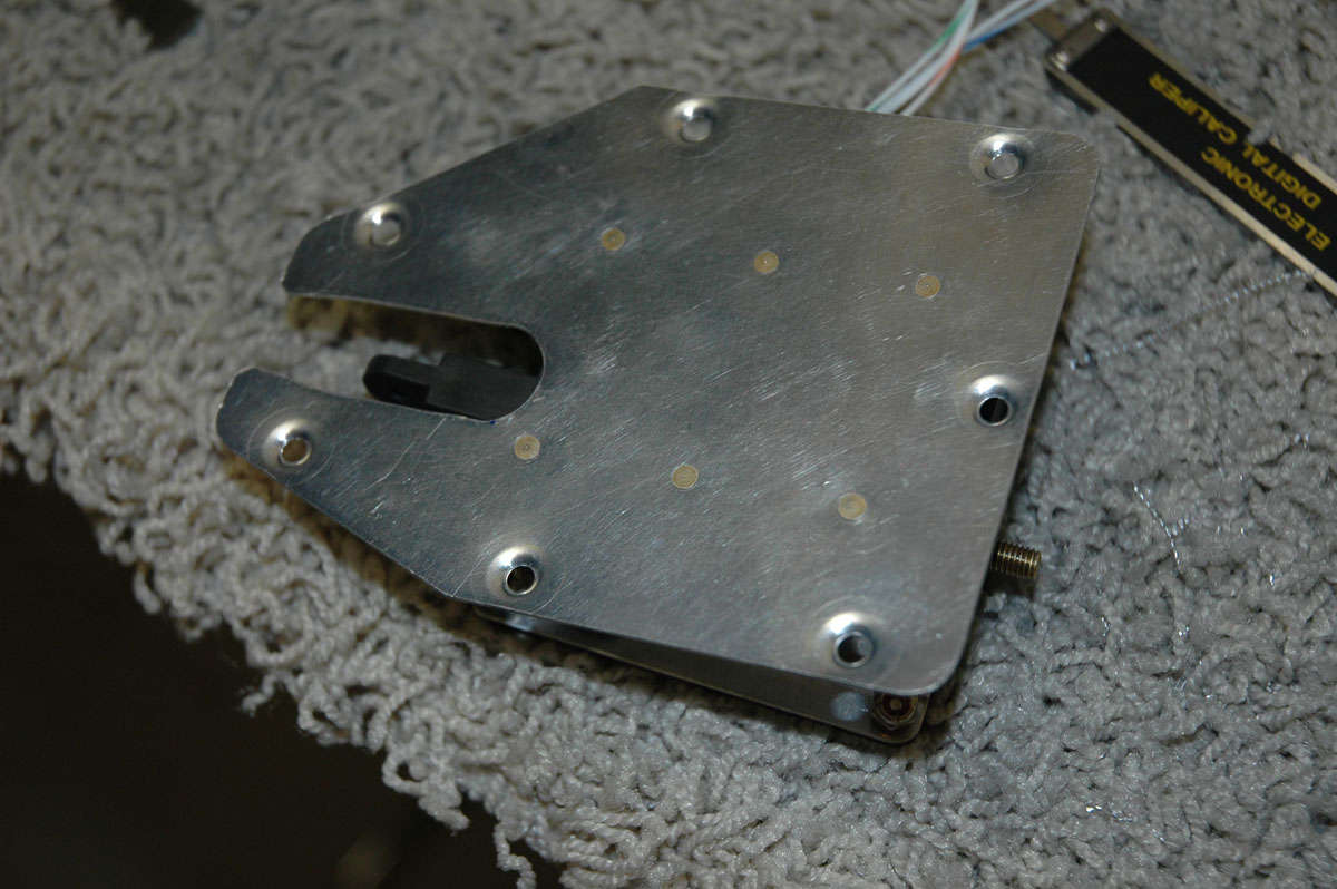
So, happy with all, I riveted the thing together. As per other site advice, I used the NAS1097AD4-3.5 rivets allowing me to countersink them with a deburring tool vs. dimpling. Smaller head, larger shank. Looks better.
Back to the trim tab, here it is pretty well done. Ended up making the agonizing decision (actually, not that hard) to use pulled rivets vs. using the rivet gun for the hard to get to rivets.
Here is a detail shot of the little riblets and how they fit into the structure. And, hey, look, two pulled rivets. These two were actually little buggers and I had to drill one out. The problem was pulling it close to the trim tab spar as the rivet is finalized. These are not structural parts...in the original design, these are the folded end tabs riveted together.
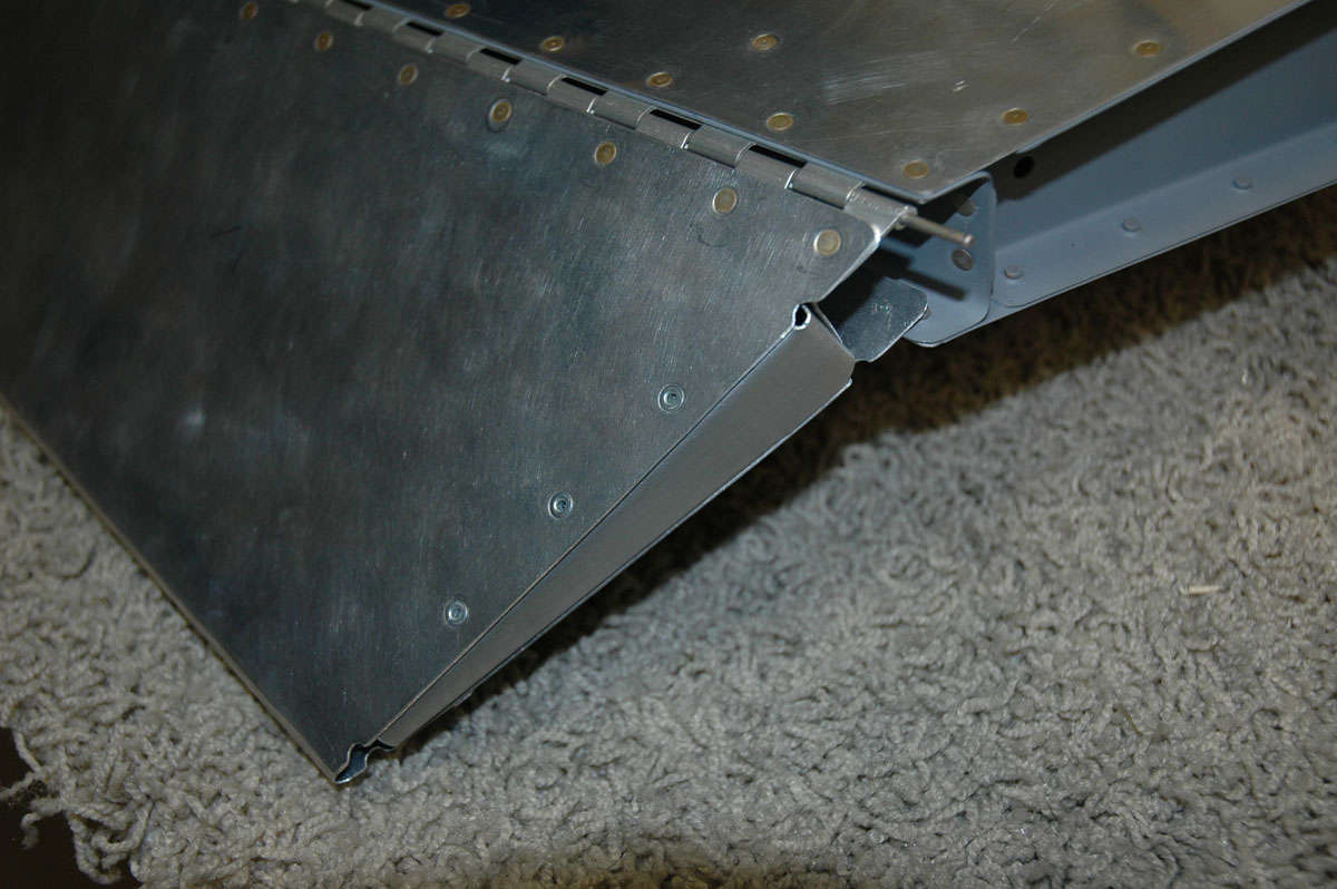
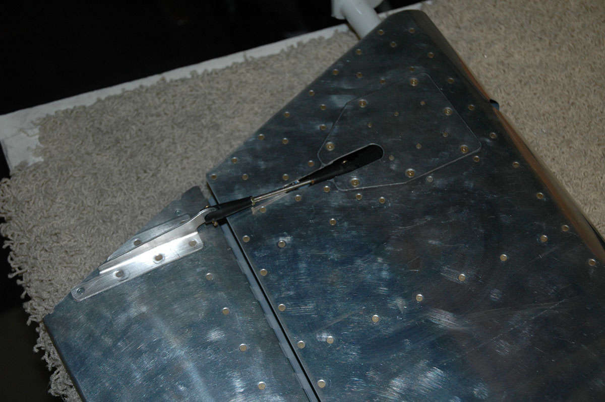
And here is the purty little thing riveted onto the elevator...finally. Seems like it took forever to get to this step. Not sure why.
And another close-up view of the inner edge of the trim tab with the riblet and three pulled rivets holding the riblet in place.
Then it was on to fitting the trim tab servo into place, with the push rod trimmed to fit and then connected to the trim tab horn. Pretty straight forward; another of those measure three or four times and then cutting progressively to avoid cutting too much. Worked out fine.
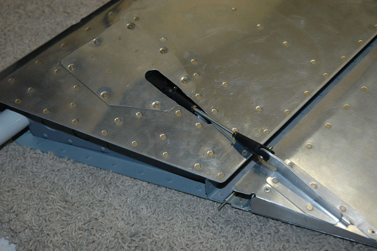
Another view of the whole thing fitted and pretty well done. The servo instructions advise that one can use a 9-volt battery and power the servo to check its freedom of travel. Plus, I found out, it's cool to see something on the airplane work. As it turned out, I needed to trim the pushrod opening a bit to make it work without interfering with the cutout in the skin.
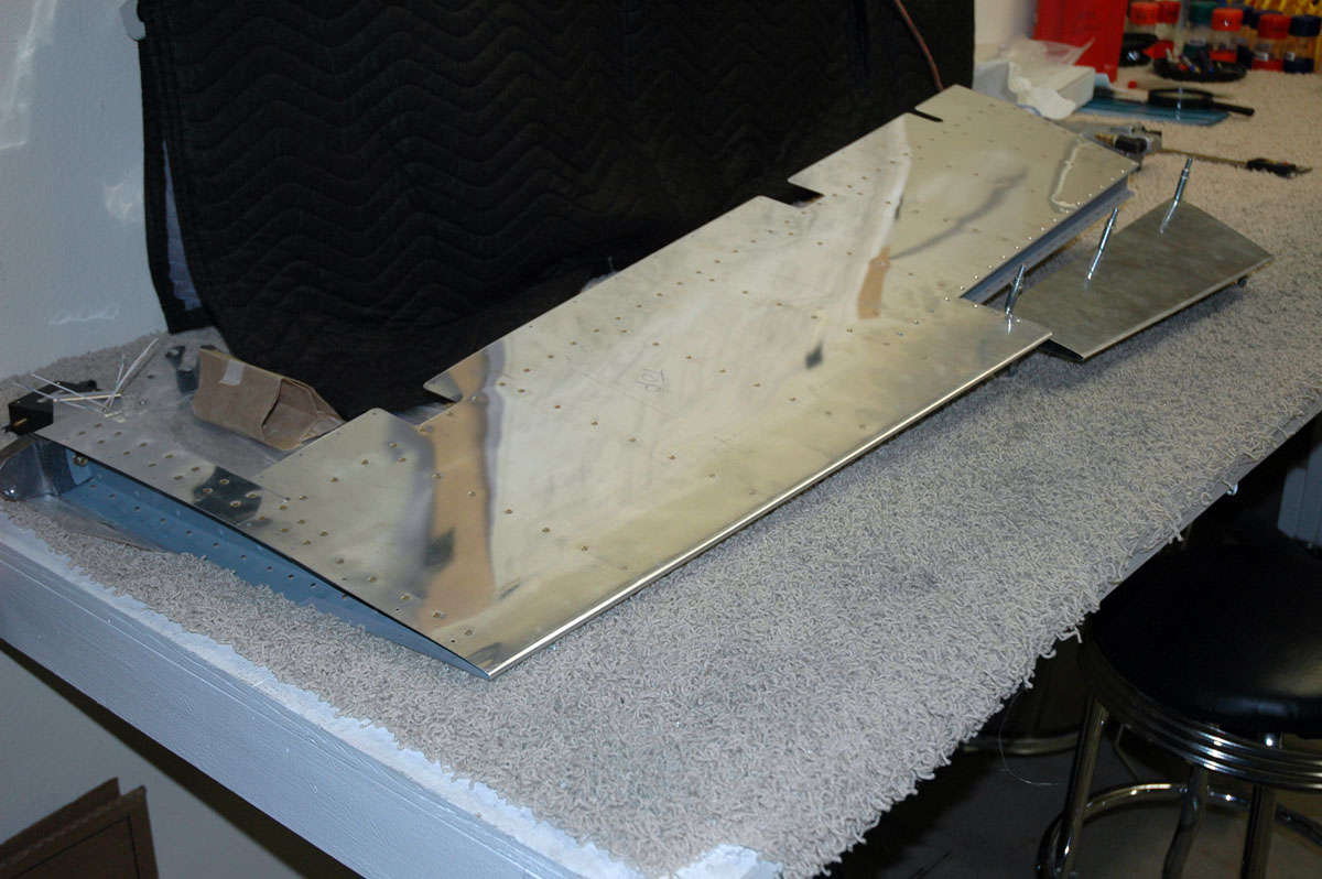
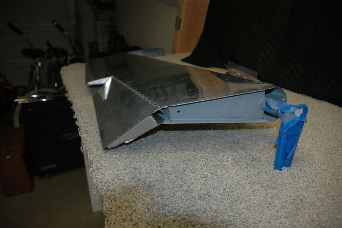
So, here it is pretty much together...trim tab attached and elevator basically done.
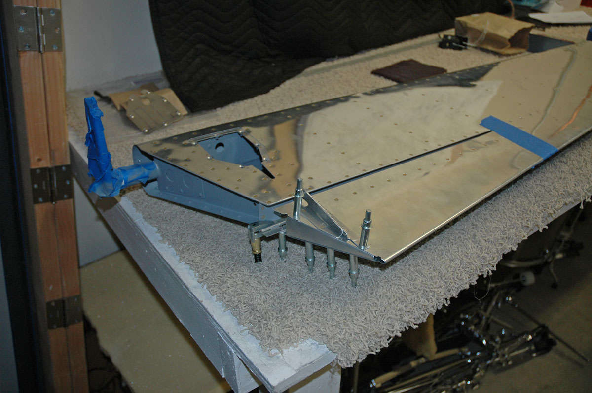
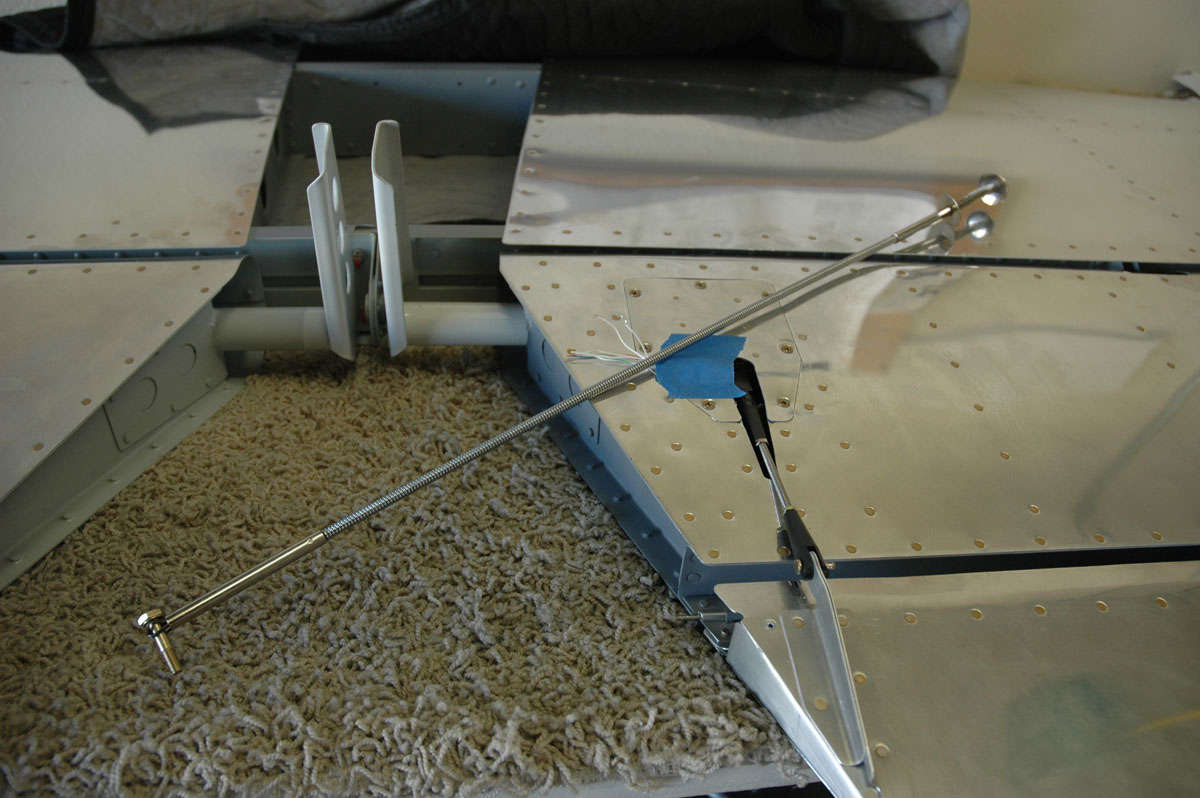
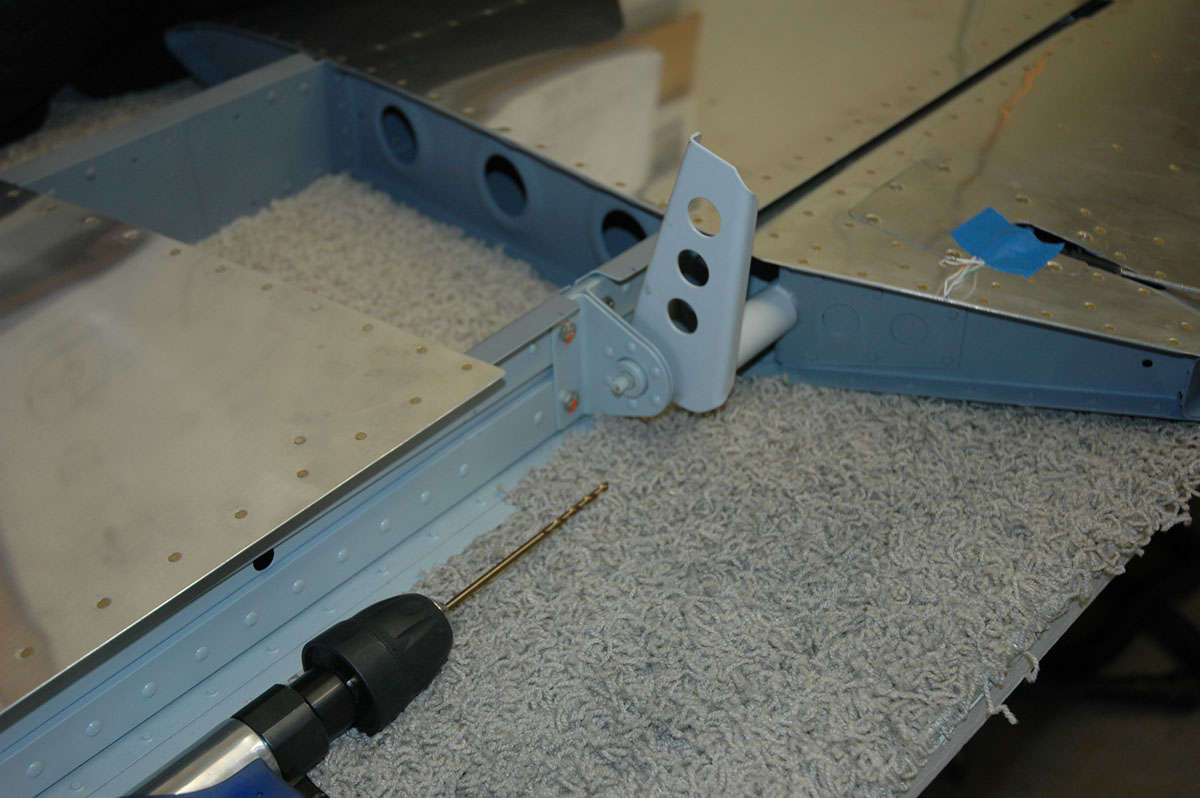
So, what's next, then. Well, I pulled the horizontal stabilizer out of the rack hanging from the ceiling and did some trial fitting of the elevators to the horizontal stabilizer.
I carefully adjusted the rod end bearings to specs, then found the specs were too tight and modified the specs a bit so it would fit correctly. I aligned back and forth, from elevator to elevator to make sure the positioning was correct. I measure at several points from the aft edge of the horizontal stabilizer to the trailing edge of the elevator.
Once I got to the part where I am trying to insert the bolts into the hinges/rod end bearings, I used a trick I utilized on the rudder: this little parts retriever will hold the bolt and allow it to be positioned for insertion.
Once the bolts were in and I was happy with the alignment, I marked the tips of the horizontal stabilizer where the skin needs to be trimmed to allow the elevator to travel up and down. Marked and masked, I did rough cuts and then filed away until I was happy. Edged it and sanded and rechecked: worked fine.
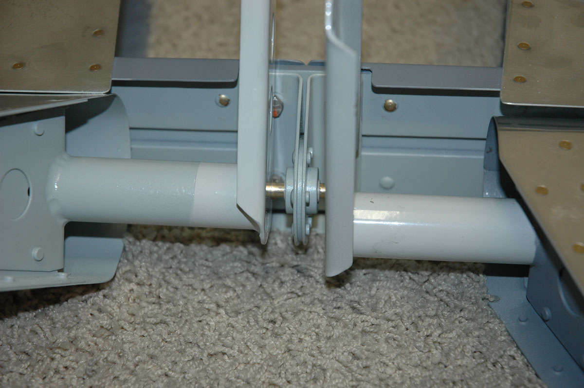
Next up: confident of the elevator alignment, one needs to drill the elevator control horns to accept a bolt through each horn and also through the center elevator hinge. Confidence is overrated; measure and think, think and measure. Use a nylon bushing, ala Lowes, to align the drill with the bearing and avoid tearing up the bearing. Drilled pilot hole in one horn, then drilled it out to 1/4 inch to accept the bolt.
Did the other side.
Fitted it all back together. Inserted bolt; fit fine; looks good; what, me worry?
And that's how my two weeks and, more specifically, my last Saturday ended. I felt pressure, internally driven, to get this assembly completed and put away. Started to rush; started to get frustrated with my imposed deadline; other things to do. Decided to stop. Come back next week. Don't want to rush. Don't want to make a mistake, well, more mistakes.
Bottom line: the elevators are done; more work to fit it all together.
Wings should arrive the second week of December. A few things I can do before they get here that will be productive like design a wing stand and figure out how to organize the inventory. I can always go back and do fiberglass tips of the tail section if I get bored. Doubtful.