
|
Fuselage Stuff |
January 31, 2012 Moving on to start work on fitting and drilling the horizontal stabilizer, I pulled the horizontal out of storage and fitted it on the aft fuselage. I leveled the fuselage laterally and longitudinally. I could sneeze and move the level by 0.1 degrees. In this view, the level is mounted across the horizontal supported at identical spots on each side, in this case at specific rivets. It is clamped at several spots.
Whoops...a milestone so a photo opportunity, as it were.

The aft spar is held by four bolts and the forward spar is held by four bolts. The aft ones are pretty simple since the attach bars already have holes drilled so it is a matter of match drilling once the horizontal is positioned properly.

Laying out where the holes are to be drilled for the forward spar needs to be done carefully, since you are near the inner edge of the fuselage top longeron and near the outer edge of a support angle. The plans call for drilling the hole 1/2" from the inside edge of the longeron which looks off center until you look at it from the other side of where you are drilling. The two inboard holes require a angle drill due to access between the top and bottom flanges on the spar right there.

Once those holes were drilled, the vertical stabilizer is next. Fitting it into position, it is time for another photo opportunity of a noteworthy milestone.

The vertical stabilizer is held in position at three points: three bolts on the bottom of the aft spar, two bolts that tie the aft spar into the fuselage top longerons, and a bunch of rivets at the forward attach plate that is then held to the fuselage by four bolts.

The vertical stabilizer is first squared with the horizontal stabilizer and then the five holes for the aft spar are drilled.

And the bottom three holes have to be carefully laid out also. The plans were not much help here; the measurements did not make sense. However, it was obvious what the intent was. The top two holes of the bottom set go through the hinge mount near the bottom of the mount, and then go through the tail wheel weldment plate near the top of the plate. Drill the holes too high or too low, and you will lose the edge distance on one of those two parts. My elevation was good and hit it right where I wanted, but my left hole was a bit too far left. Not really a problem, but it is closer to a curve on the tail wheel weldment than I would have preferred. The bottom hole of the three is just carefully centered and drilled.

The top two holes on the aft spar are drilled through from holes already drilled on the angle control stop; pretty straightforward but this also requires an angle drill.

And then we come to the fly in the ointment for this week. Before the vertical stabilizer is mounted, the plans specify to trim 9/16" off the bottom edge of the spar. Okay, I did that. Maybe not the smartest move. Once I fitted and drilled the aft spar, the vertical is centered laterally (a bit awkwardly if the plans are followed) and then the vertical position is adjusted at the front attach plate to align the three rudder hinges on the aft spar...take the bend out of the aft spar, in other words. Okay, that was done but then the lower edge of the VS-702 spar sits high enough that there is insufficient edge distance if I match drill the attach plate.

After all this time, you would think I would have the sense not to trim metal until after everything is fitted. This has happened before. I'm not sure why mine sits like this. I've done a internet search to see if others have encountered this and came up empty. I also double checked the piece I cut off...less than 9/16" is the residual piece.
I have an email in to Van's with this photo. I think the easiest fix will be to fabricate a new F-884 attach plate and drill the bottom row of holes 1/4' higher. That should take care of it but we will see what Van's says. Scratch my head and move on, eventually.
February 5, 2012
Moving a bit into another direction while waiting for Van's to respond to my request about the vertical stabilizer attach plate, I did the prep work for the bellcrank bearing that will attach the two elevator push rods that join the control sticks to the elevator. Straightforward; just needs to be primed now and riveted.

Van's came back with an answer on the attach plate pretty quickly. I was told that I could just drill another row of holes higher on the plate to provide sufficient edge distance from the trimmed edge of the vertical stabilizer spar. I looked at this a bit and decided that might be okay but I'd rather not have the extra holes in in the plate. So, I fabricated a new part that was drilled to provide the proper edge clearance. Here is the original part on the left and the new one on the right. Should work just fine.

Here is the part fitted and drilled on the stabilzer spar. A bit more prep work on this part and them primed and riveted into position.

The other side of the plate after the match drilled holes were enlarged with a #12 drill to accept the AN3 bolts.

After priming, here is the fabricated part on the left with the old one on the left. Still have not determined why I had this problem in the first place but it worked out okay with a bit of extra work.

Not pictured, I also did the prep work on the two elevator push rods. Basically, the two tubes are cut to size with the rod ends drilled and then riveted onto the ends. They are primed inside and out and now ready for installation. Not as happy with the smaller push rod (F-840); the rivets are not as even as they should be in spacing or edge distance. However, this is more a cosmetic issue so I will move forward.
I also received a hardware order from Aircraft Spruce that will allow me to finish up a few nut plates on the fuselage floor that were left undone. The project goes on the back burner for a few weeks now as I have two weeks of travel for my job that will keep me otherwise engaged.
February 28, 2012
Over the past three weeks I seemed to have made three steps forward and two steps back. I have not had the opportunity to spend any consistent time on making progress. Nonetheless, I did get a few things done.
As noted last time, I completed the elevator push rods and then worked to install control sticks in the fuselage. This required reaming the mounting hole on each stick, and also some careful assembly work to get the mechanism put together properly. Here is the forward stick installed.

And a look from the back forward showing both sticks. The front stick remains too long and will be cut down at some point to the correct length with a stick grip added.

Here is the elevator bellcrank completed and ready to be installed.

And here it is installed with the forward push rod also installed between the stick assembly and the bellcrank.

Here is the attach point between the stick assembly and the forward push rod. The masking tape is a reminder to me that these parts have not been tightened down. They are awaiting a final adjustment of length before tightening. Also seen here is that all the floor nutplates have now been installed.

Another thing I was able to do was to install the front seat throttle. It went together easily but I am not really happy at this point about how the top plate fits over the throttle assembly. There is a pretty big gap between the two parts and I may follow the paths of others and rework this part to fit better.

I used the upgraded rear throttle available from Aircraft Spruce. I had received this several months ago and when I went to put it in I noted a complete lack of instructions for the adapted parts. I thought it would be a drop in replacement but it is not. It was easy enough to modify to make it work but it does take a bit of thinking and rework.

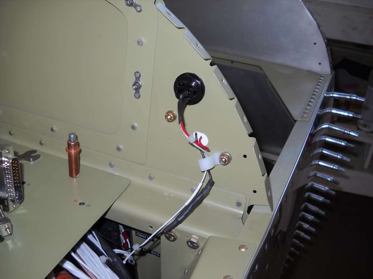
Here's the backside of the assembly. I wish I had had this photo when I was trying to figure out how to make it work. I have since reversed the bottom bolt so the nut is on the inside. I realized that this throttle did not need a friction lock; it is dependent upon the front throttle, to which it will be eventually attached using yet another mod kit.

So, it got a bit more interesting when I mounted the elevators again and connected the elevators to the push rod that connects to the sticks. Pretty cool for a few minutes...moving the stick and seeing the elevators move in unison...making airplane noises and such.
However, I was starting to work on the elevator up and down stops when I discovered my elevators were not aligned. I clamped the left elevator and noted this on the right side.

From this angle it doesn't look like much but it was out of whack quite a bit from where the centered left elevator was. I put a level across the two elevators and then measured their respective angles and then used a laser level to try and figure out what the problem was. I have almost a one degree split between the elevators. Not what I wanted to see. I determined my problem was with the way the right elevator control horn was drilled by me a few weeks ago. Somehow my pilot tool, made of hard oak wood, allowed me to drill at a bit of an angle, enough so that the hole in the control horn was off by at least 1/8 inch...probably more like 1/4 inch.
I did not like this and did some online research. Not the first guy to do this, not surprisingly. Some guys fixed it by welding the hole closed and redrilling. I asked Van's about this and they said that was acceptable but I'm not so sure. Looking at the FAA's guidance, it notes that is not an acceptable practice to fix and oblong hole, and my hole is a quick drilling away from an oblong hole. After consulting with my own experts, and they are good, I have decided to remove the offending control horn and end rib, and reassemble and redrill the two control horn holes. Not what I want to do, but $38 later, I have a new control horn coming and soon enough I will have another side project to keep me busy.
But before I got too bummed, I did shoot this photo of the tail with the rudder mounted. You can't see that the right elevator is off the tail in this view, set aside for dissection. The rudder was mounted here so I can complete the rudder stops.

And here is the left rudder stop clecoed in position and ready for trimming to size. I studied over the drawings for a while and never could figure out why Van's wanted them trimmed the way they did, so I used a bit of common sense and trimmed them so they kept the rudder surface no closer than one inch from the elevators. Then I primed and riveted them to the fuselage.

I had a bit of time Sunday so I did a pre-assembly assembly of the rudder pedals to see how these are going to come together. Looks good; this is the next new project that is coming.

I have some old tasks to complete also to bring me up to where the plans are. I ordered a EFII fuel boost pump after looking at my various options. Once that pump arrives, I will fit it into the forward fuselage to the left of the rudder pedals and mark the mounting holes. I want to get the nut plates installed that will accept the bolts that will hold the pump in place before I attach the bottom forward fuselage skins. I also want to drill and probably mount the rudder pedal angles before adding the fuselage skins. After that, though, I'd like to rivet these skins and get that part done. Then, I want to correct my elevator error, redrill the push rod attachment hole, and then measure and cut the elevator up and down stops and get those completed. After that, I will run the rudder cables and do a test fitting with the rudder pedals before I remove the empennage again and pack it all away for another year or more. Next time I mount them, it will probably be permanently. Then I will push forward on the next steps in the fuselage construction.
March 13, 2012
Step one in the past few sessions was to fix my elevator horn drilling error. The two parts arrived from Van's and I proceeded to remove the rivets holding the end rib and part of the skins.

I then drilled out the offending control horn and replaced it with the new part, as well as the new end rib. I then very carefully drilled the two holes in the horn for the bearing and the control rod attachment. Did a much better job on the latter hole this time and after all was said and done, the alignment of the two elevators was spot on. Time to move on.
Once the elevators were set up properly, I was able to complete the elevator up and down stops. As can be seen here, if you know what you are looking at, the two horns are not aligned evenly, even if the elevators are, so the up and down stops had to be trimmed to meet the horns equally. It makes more sense if you look at it.

After all that was done, I removed the elevators and other empennage parts and carefully packed them away again. I'm done with them for now and, actually, probably until I do the final mounting of them.
So, I moved on to get serious about putting together the rudder pedal assembly. First off is the fabrication of two thrust washers that are made from a couple of small nylon sheets. It has to be laid out carefully to fit the required parts from the sheet, but the process is straightforward.

Here is one of the completed nylon thrust washers that fit over the piece next to it and provides a bearing like surface to turn against.

And here is the rudder pedal assembly, less the pedals themselves, assembled and fitted into place on the forward fuselage floor. I had already drilled out a couple of previously set rivets on the firewall angle to accommodate the two rudder pedal angles.

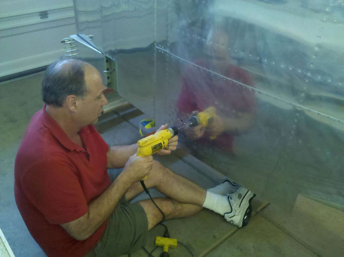
Here, the prior drilled pilot holes are being drilled to #30 for the AD4 rivets that will hold the angle to the floor, soon enough.

Final drilled and clecoed into position for final fitting. Looks good to me.

I set that aside a bit and went ahead and installed both rudder cables working, as per the plans, from the aft forward. Next to the center section, the rudder cables have a plastic sheath that is zip-tied to the structure to hold it in position. Not elegant or fancy, but I guess it works. The plastic sheath prevents the cable from rubbing against the foot wells provided to the rear seat passenger.

After the cables were installed, I assembled the rear seat rudder pedal parts. Much of this work was done earlier on the floor seat angles, so on this day it was pretty much just the assembly of the actual pedal parts. A fitting is riveted into each end of the tubes and a rod end bearing is screwed into position. Comments have been made since day one, no doubt, about these "pedals" but the idea for me is to have them in place to allow the rear seater to fly the airplane if he or she wants to, and thus have stick, rudder, and throttle control. Works for me, if not all that elegant. No brakes either.

Here is an overall view of how the two rear pedal assemblies tie into the rudder cables and, further, to the front rudder pedals.

Speaking of rear throttles, I went ahead and started work on installing the rear throttle assembly. As noted in another section, the quadrant I got from Aircraft Spruce is not a drop in assembly; rather, this section of the arm rest needs to be removed to allow the quadrant to be installed. Note for orientation, the fuselage is rotated 90 degrees in this view, so I am working on it horizontally. Nice part of having the fuselage on a rotisserie.

Here it is with the section removed and nearing completion for the fitting of the quadrant. Slow work to get a good fit.

And here is the rear throttle installed in position. Fitted well. Still to go is the careful fitting of the rod that connects the forward and aft throttles.

I have looked at issues with rudder pedal geometry that seems to be problem for some with the RV-8. The main problem seems to be that the pivot point for the brakes is at the bottom of the pedal, so any firm pressure applied to the rudder pedals may cause the pedals to pivot forward and inadvertently apply the brakes. I looked around online and considered adding pedal extensions. I sketched out what I thought would work for my size thirteens and made them as long as possible, then shortened a bit in the fitting. These are a bit longer than most designs I've seen but I figured I can trim later if they are too long. Easier to trim them shorter than redo them. This length will give me a large area for rudder pressure beneath the pivot point; I can slide my feet up a bit for braking. We'll see but not for a few years, I guess.

So I took some .125 inch aluminum stock and cut and bent the pieces based on my template. Here they are fitted together to see how it would work.

And here they are bolted to the rudder pedal assembly for fitting. I proceeded to drill and do the prep work for the two extensions based on this fitting. I will spend the next sessions finishing them up and then priming some of these odd parts I've put together in the past few weeks.

I'll finish these control assemblies up and install them, plus take care of a few other leftovers before moving on to initial fuel, hydraulic, and electrical system work.
March 29, 2012
Finished up the rudder pedals and put these assemblies together. We will see how this works out when I am able to sit in the cockpit at some point in the next few months. Hard to tell without putting feet on them.

And here they are temporarily installed in the fuselage.

Moving on the the the EFII fuel pump installation, I positioned it in the forward left fuselage and adjusted it to where I thought it would work best. At this point I am thinking of mounting the pump backwards to allow the fuel lines to fit better; i.e. the intake line will run to the front of the pump and the outflow line will run from the back of the pump to the firewall fitting. We shall see.

As for the pump mounting, it doesn't really matter if it is mounted one way or the other as far as the nutplates are positioned. The pump came with an sized sheet of aluminum that decided to use as a stiffener. Here it is in position and being drilled for flush rivets.

And here it is after we riveted in both the stiffener plate as well as the rudder pedal mounting angles.

I also spent some time working on the front and rear throttles to connect them together. The front throttle needs a hole added for the push rod that goes between the two throttles. The rear throttle also needs an additional hole drilled, but I decided to shorten the throttle a bit so it would fit better in the allowable space in the rear cockpit, so I took off enough of the rear throttle that the existing hole will work for the pushrod attachment. Easier to see than describe; trust me.

April 12, 2012
Not a whole lot of progress over the past few weeks, otherwise busy with work, family, and other higher priorities. However, I did do a few things....
For example, I drilled a small hole in the flap actuator that is used to safety wire the rod end bearing to the mounting fitting that bolts to the fuselage. From my unpracticed eye this seems to be a bit of an unorthodox use of safety wire as it is there to actually keep the rod end bearing from spinning out of the actuator if the locking nut loosens. Okay. It is as per the plans. The only gotcha I figured out later was to be careful not to drill the hole too close to the center of the actuator or the nut will cover the hole and not allow access for the wire. Mine was close but it worked. I should have a photo of the completed assembly with the safety wire but, I don't.

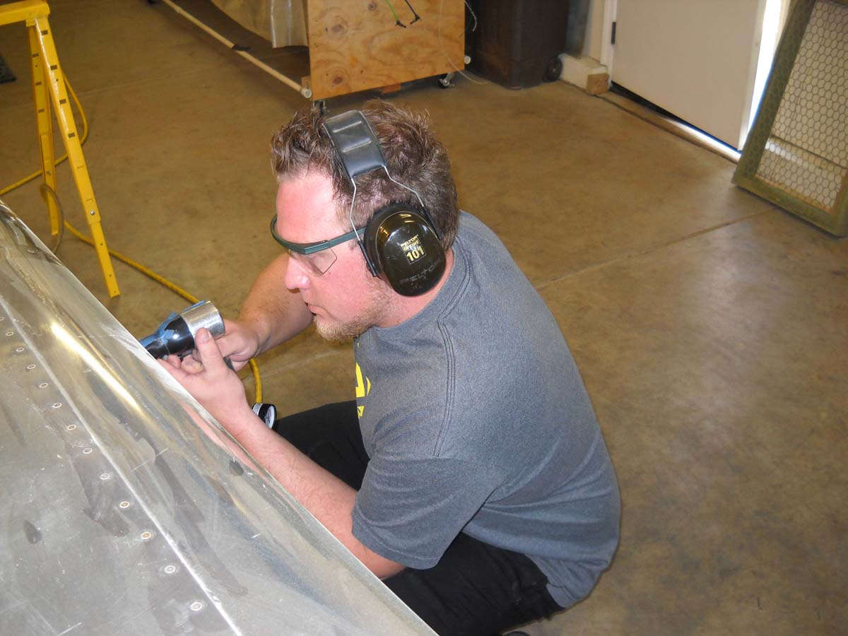
Did some riveting on the bottom forward fuselage skins. These were fairly straightforward but somewhat delayed because I need my able bucking partner who is only available on Saturday mornings right now, and then just for a couple of hours. Last Saturday we had a few delays and only got part of the job done. Here I am doing some solo riveting. To provide access to the aft crossmember, the skin is lifted up and a bucking bar can be inserted. This is obviously done before the forward crossmember is riveted to the floor. I noted that some guys have tried it the other way and it doesn't work.

Here is a view of the floor of the forward cockpit with half the lower forward fuselage rivets done. You can't really tell that unless you know what you are looking for, but trust me. The other side will be done this next Saturday if all works as planned.

And here is an exterior view of the lower forward skin on the side that is done. After the other side is completed, the cooling ramp is added between the two sides and that part is then pretty near complete.

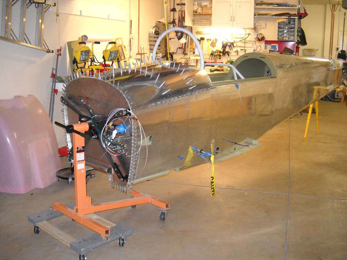
Here is the current state of the fuselage from the right side.

And, not surprisingly, here is a view of the left side as we stand now.

Other stuff I've worked on with no photos: linking the rear and forward throttles and also adding individual hydraulic reservoirs to each of the rudder pedals. More on those later.
May 15, 2012
A month since any updates...busy month for doing other stuff but there were some things I did do on my RV-8 that is slowly coming together.
I had some guests in town and put some of the parts I have been working on over the past months. This was not only show and tell, but a chance for me to take a look at how some of these parts will fit together as I plan brake and fuel lines, and also where wiring will run and how much room I have to deal with to stuff all this stuff in.
So here is the forward fuselage with the blank instrument panel plate clecoed into position. Behind it is the forward bulkhead and the firewall in position. The installed rudder pedals are there too.

Another view of the forward fuselage.

As part of working on the aft fuselage, I did some preparation work on the gussets that attach the top longerons to the aft cockpit bulkhead. The plans offer installing homemade nutplates to allow a place to store the tie down rings when not installed under the wings. Here I am tapping the homemade nutplates to receive the tie down rings.

A view of a gusset clecoed with a nut plate ready for finishing.

Working on the aft fuselage, I did the prep work on the four aft fuselage bulkheads.

More on the aft fuselage, the upper skin is clecoed on for skin drilling, followed by dimpling and final prep work.

Another view of the aft fuselage.

And then the finishing kit showed up. Cool. Big bugger; it holds the canopy, engine mount, engine cowling, tires, wheels, and brakes, and more stuff.

Well packed together. The canopy is special order item with a higher UV protection; otherwise, standard. Had to find places to store all these parts.

Continuing the preparation on the aft upper fuselage bulkheads. Primed and set aside for riveting.

The upper aft fuselage skin prepped. Had some orange peel during the priming; first time I've encountered it on a substantial scale. Had the gun set up wrong. To be fixed.
May 21, 2012
I had a short weekend...a quick turnaround between work trips, so I did not have much time to devote to airplane building. However, I did manage to rivet three aft fuselage upper bulkheads into position, and also added the fuselage gussets that attach to F-807, the bulkhead immediately aft of the cockpit.

So, all but the very aft bulkhead is permanently attached. I've looked at the very aft bulkhead, the one just forward of the stabilizers, and want to see if it is possible to leave this one unriveted until I rivet the top skin into place. It seems to me it would make the riveting job much easier if that bulkhead can be removed to help make access to some hard to reach rivets much easier. I can't have been the first to think of this so it probably is not that easy. Stand by for a few months and we will let you know.
Another view of one of the bulkheads, this being F-809.

And a view of one of two gussets with the tie down ring storage nutplate riveted into position. Looks good to me.

I also took the time to build, as per the plans, two aft fuselage floorboards for use when the aft skin is riveted. For the forward one, I doubled up and glued/screwed two pieces cut from the finishing kit craft top. Should work just fine the one time I use it. Then, firewood. Can't say the craftsmanship is great but it will work.

After I did this work, and also reshot some primer on the aft upper skin, I did a short assessment of what is next. In rough order, here is what is coming: install the aft fuselage static ports and static lines; construct an aft shelf to hold what I hope will be a Dynon ADHARS unit for what I hope will be a Skyview system; run shielded cable through the aft fuselage for what I hope will be an AeroLED tail strobe; run five-wire twisted wire from the forward fuselage to the tail for the elevator trim; all of these things will pretty much finish up the aft fuselage and allow the upper skin to be riveted into position. Interspersed in this work will be my initial efforts at bending tubing for the brakes and fuel system, then installing that tubing and associated fittings and valves and fuel pump. Then, the next day I will.....well, that is actually several months of work. At some point, the forward upper fuselage will be fitted and drilled and clecoed into position. Somewhere in there I want to mount Dynon servo mounts in the wing and the fuselage for autopilot aileron and elevator servos. And run shielded cable and wiring in the wings. Then rivet the bottom wing skins. Then, a milestone to fit the wings to the fuselage. Measure often, drill once. I suspect that I am looking at late fall to get to this point. Okay, then.
June 6, 2012
A quick update on this, the 68th anniversary of the D-Day invasion of Normandy. The past few weeks have continued busy with everything but building an RV-8. What time I had seemed to be a series of disjointed sessions trying to get my bearings on proceeding forward. I expect to be able to get back into it in a bigger way in the near future.
Nonetheless, I did make a bit of progress. I built a shelf that I hope will one day hold the Dynon Skyview ADARS, the attitude and sensing component of the Skyview system. This shelf will mount in the fuselage just aft of the cockpit. I built it to hold two ADARS units, which probably would never happen, or possibly hold another piece of equipment at some point in the future.
I laid it out simply using two pieces of angle and some extra aluminum sheet.

Riveted it together and positioned it where it will go. The cardboard cutout is the footprint of the ADARS box positioned where I expect it to go. I also added another piece of angle (not seen here) forward of this shelf to hold standoffs for the three air lines that go to the ADARS: static, pitot, and angle-of-attack lines. At this point, I have to plan on what I think will be at some point years away.

Speaking of static lines, I carefully measured, according to the plans, the location of the two static ports to be installed on the sides of the aft fuselage. I am using SAFE-AIR ports and after all was done, I used pro-seal to attach the ports to the inside of the fuselage.

I thought about adding the optional rivets to assist the pro-seal but decided against it based upon possible disturbance of static air in the immediate area due to the rivet surface irregularities and the complexity the rivets would add to a relatively simple job.
Here is a view of one of the ports from the outside.

After three or four days of watching the pro-seal cure and thinking, maybe agonizing, about how to route the static lines forward, I just cut the raw SAFE-AIR tubing and attached it to the static ports. They tee together and run forward, eventually to connect into that ADARS box a few feet forward of the ports.

I will tee the static air again, though, and run a static air line to the area behind the instrument panel because, at this point, I plan to install a backup airspeed indicator and altimeter, both of which need the static air source. Alternate static air source? Probably not...I do not plan an excessive number of backup systems for what will presumably be a VFR sport airplane with light IFR capability.
I also placed some parts order and will shortly have on hand: Dynon pitch and roll servo mounts to install while the access is easy (no servos yet), shielded wire for my planned Aero LED navigation light/strobe lights to be run through the wings and aft fuselage; pitch trim wire to run through the aft fuselage to eventually be attached to the pitch trim servo in the elevator; and some other doo-dads. As can be seen, I am trying to do the installations in the aft fuselage so I can attach the upper skin in this area.
June 24, 2012
Two weeks since I added anything here because I've had some time to work on the RV-8 and did not want to divert time elsewhere to things that could wait. However, I did want to post some progress in the several areas I've been working on.
Fuel line bending. Despite this photo, I've made and installed all the fuel lines except one. I had 12 feet of 3/8" 5052 alloy tube I used to make the fuel feed lines from the wings to the valve, and from the valve to the fuel filter, and from the fuel filter to the fuel boost pump, and from the fuel boost pump to the firewall. I used the trial and error method, mostly, and also used a good portion of the 3003 alloy tube that came with the kit. This pile of bent tube prototype was my effort to get the last tight piece from the fuel valve to the fuel filter. I was trying to get fancy but my skills are not equal to the task. In the end, I ordered a 90 degree elbow to go onto the bottom of the valve and then will construct a long "s" turn tube to fit. But I also need some new 5052 tube. About two feet will do but will probably have to buy six feet again.

Here is the fuel pump installed. I decided to go with a reverse flow routing to make the process easier. Note the missing fitting at the firewall. I had to borrow it for some work at the gear tower. Ordered another one. Coming soon.

And here is the fuel valve (above) and the fuel filter (below) and the two connections that don't yet. My solution will be the 90 degree elbow at the valve pointing forward (right) and that should connect to the filter with a tube with two "u" turns. I did it with the 3003 tube and it worked okay.

Here is the entrance point to the fuselage where the fuel tanks will connect to the fuel system. These will be cut down to extend about 3/4" from the side, but I think I want to try and pressure test the fuel lines so I have not trimmed them down yet. Need some room to play with.

I constructed the fuel vent lines using the 1/4" 3003 tube...not under pressure so I figured the Van's tubing would suffice. I installed the vent tubes as per the plans...some guys don't like the tubes in the gear towers and do it differently. I did not see a problem and they went together quickly. No photos, though.
At some point I started work on installing the elevator servo mount. I have pretty much committed to using the Dynon Skyview system, and purchased the servo mounts for both the aileron and elevators so I can get them installed before I start losing easy access.
Here, I've marked an area on the bulkhead just aft of the bellcrank for trimming to accommodate the servo mount.

And trim I did.

Here are the two mounting plates clecoed into position, one on each side of the elevator bellcrank mount.

And here they are primed, finished, and riveted into position. As per the plans, the servo will mount here using the aft hole and only the hole that holds the bellcrank bolt, at least if my reading of the plans are correct. Some guys try and use the third bolt hole but it will interfere with the bellcrank. No need to workaround; follow the plans and don't install a third bolt.

I am no longer a wire virgin. I ran some wire to the tail. Here is the shielded three conductor wire for the tail position light/tail strobe (probably to be AeroLed) and the five conductor elevator trim servo wires. I pondered how to do this for some time then decided to just start something and do it. Done. As can be seen, I am trying to get everything in the aft fuselage done before riveting the top skin on.

And here is the pitot, static, and AOA tubing running into the aft fuselage from the wing joint area.

A closer view of where it comes in from the wing. The blue AOA tube only runs aft to where the Dynon ADAHRS unit will be mounted. The green pitot source tees for the planned run to the instrument panel with the white static air.

As part of the planning process, I have considered using the VP-X Sport as the basis for my electrical system. Several advantages, not the least of which is simplicity and multi-tasking and the interface with the Dynon Skyview. A bit pricy, though, and some flexibility is lost. The decision is not yet made, but as part of the process I wanted to see where I could install the unit. I constructed a mock-up from high quality cardboard (don't look too closely...the post office might be upset) and tried different places. Does not seem to fit anywhere very easily, but this seems to be a good spot to me. I would lose some of the baggage area but it would be simple and clean to mount it here. Would add a cover for protection. Easy access to the back of the panel for wiring bundles.
Truth be told, after considering this for a couple of weeks, I am back in the 'build it myself' camp using, primarily, fuse blocks in lieu of breakers. We shall see.

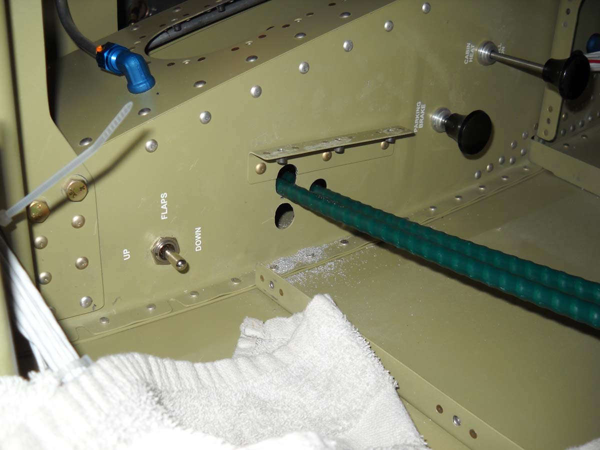
As part of this process, though, I decided to go ahead and add a panel from the top of the forward baggage compartment to allow easy access to the rudder pedals and the brake lines there once everything is buttoned up. Here is the panel laid out on the baggage compartment floor.

Cut out and under construction.

The panel access modification is completed here after the rivets were installed. As part of this process, I removed the underfloor stiffener and will replace it on the aft side of the panel with a scratch built bracket to hold the parking brake valve. More to come on that modification also, but it is all part of working on this part of the fuselage right now.

Here is the panel cover being fitted.

And here it is all done except for priming. In retrospect, I got a bit carried away with the nutplates and screws. Half of what I used would be fine, I think. Not structural as far as my eye can tell. Won't have it open very often, though, so it won't be a problem to have a few more screws than needed.

As part of the process of finishing work on the aft fuselage, I patched the hole on the left side of the fuselage that holds the RV-8A wing step (for the nosewheel versions of the airplane). It makes more sense to me that if you have an RV-8A you cut a hole here rather than having the RV-8 guys deal with a hole here, but no one asked me. If left alone, it is covered by the fiberglass wing fillet fairing, but I have also heard that leaving it increases the airflow in a bad way inside the cockpit, so I patched it.

Straightforward process just done carefully.

Patched and ready for riveting once I do a bit of priming. Worked out just fine in my book.

The last project I have started is building a bracket to hold the ELT and the transponder on the side of the right fuselage adjacent to the battery. I have laid out an 8" x 8" panel that I will construct of heavy stock aluminum as soon as I get some. But, here are the angle brackets fitted and drilled onto the longerons. One problem will be the need to use universal rivets on the upper mount where countersunk ones should be used. Can't get a countersink on the longeron now and I think the universals won't be too much of a problem below the baggage compartment floor that will install above them. We shall see. If it is a problem I can modify the floor a bit, I think.

And that is where it's at right now.
July 10, 2012
More progress over the past week. I did some detail work on some brake parts and finished the brake lines for the interior fuselage. We also riveted the turtle deck on (aft upper fuselage skins) and I started some preliminary work on the forward fuselage area.
The bracket I made to hold the parking valve worked out particularly well, at least in my limited experience. Here is a view of the valve beside the bracket, which is designed to attach both to the baggage floor and the adjoining bulkhead.

And the two parts married up together. The three nutplates attach to the baggage floor.

And here is the baggage floor where the three screws indicate where the nut plates are on the bracket below, plus the two bolts that hold the valve in place, and the two nutplates that attach the bracket to the bulkhead. Cool.

The other side of the same assembly.

With the valve installed.

Another view bolted into position. The point of this was to allow the valve to remain installed if the baggage floor is removed and to provide a solid mount for the parking brake control cable, yet to be installed, which attaches to the lever on the right.

The valve is in the center with the two brake lines running laterally to the landing gear towers, where they drop to the fuselage bottom to emerge in fittings to be eventually be connected to the brake lines running down the gear legs.

No real pictures of attaching the upper aft fuselage skins, but they are now attached. I had to set the fuselage on the sawhorse to stabilize it so I could crawl into the aft fuselage to buck the rivets. Tight fit but it worked out okay. Nathan, one of my sons, continued his role as expert rivet gun operator.
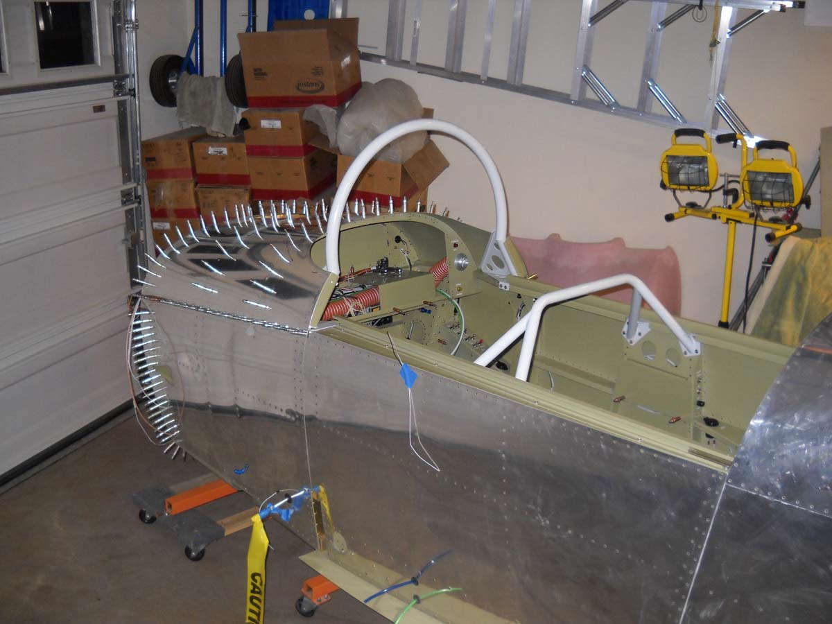
Since the fuselage was stabilized on the sawhorses, I took the opportunity to get into the pilot's seat for the first time. Besides making airplane noises while sitting there, I also wanted to see how I fit and how the rudder pedal geometry would work.

Here I am making the airplane noises, probably wondering what I have gotten myself in to. Actually, it was a significant moment for me to try the cockpit on for size. Fit just fine. Just add a few parts and away we go.

Rudder pedals worked fine also, at least for my little test flight. They are not attached to anything so it wasn't a good test, but I could apply pressure to the rudder cables and get an approximation of how they will work out.

And Nathan had to try the cockpit out also. He needed to don his "stunners" (his term) to get the right image. Not a pilot yet but maybe someday. Probably a Phd. first.

On to some work on the forward fuselage. Here is the instrument panel being laid out with the two subpanels and bracket for drilling and preparation work.

And one cannot just lay the panel out without also putting it into position to check it out. Note that the main panel is dropped one set of screw holes, as per the plans, to allow access to the holes that needed to be drilled.

That exercise was more than daydreaming, though, as I was a bit concerned after reading some reports of guys having problems fitting the Garmin GTN-650 into the RV-8 panel due to the tower cross brace located behind the panel, and also just the depth available. I make it about 12.5 inches of room above the cross brace; a call to the fine folks at Steinair and Chris in particular revealed that with a bit of planning it is not a problem. Figured as much.
Did not have a lot of time to work on the plane over the past week. However, I did do the prep work for the top forward skins, which included clecoing it into position and then drilling. First look with the top forward skins in place.

Another view looking into the cockpit. The skins were trimmed and edge finished.

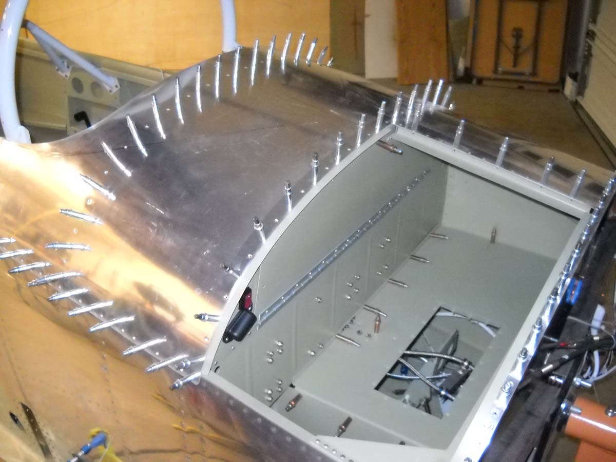
Looking down into the forward baggage compartment. Once the top skins are riveted into position much access into this area is lost. You can still get into it but it is more complicated; thus most do not rivet the skins until the last possible moment. I expect I will do it sooner since I want to paint the fuselage before the panel and engine go in.

A view of the instrument subpanels and the area where the panel will eventually be mounted.

Here are the little parts that tie the aft part of the upper skin to the canopy frame weldment. The skin lies flush on the part, and it is then riveted to the weldment. Just doing the fitting and drilling here.

No photos here, but I did lay out my basic electrical schematic. It will have a main bus, an avionics bus, an essential bus, and a hot battery bus. Pretty standard. The main bus and the essential bus will be broken down into sub busses with a bus for breakers and a bus for fuses. I think it is a good starting point. I continue to make slow but steady progress.
Moving forward with the forward fuselage and also ordered some of the electrical components I need.
Since the forward skin was prepped and ready for priming, I went ahead and did the same for the forward baggage door so they could all be primed at the same time. Did the skin and other part edge finishing and then clecoed it all together. All the holes were drilled out to #40 or #30. The piano hinge was also cut and drilled for later installation.

Another view, this of the door interior.

I drilled the instrument sub panels, both sides, for eyeball vents and toggle switches. After doing a bit of research, I will probably buy the Steinair vents as they seem to be the best as far as sealing when closed. The five toggle switches on the lower left panel will be for lights and the fuel boost pump.

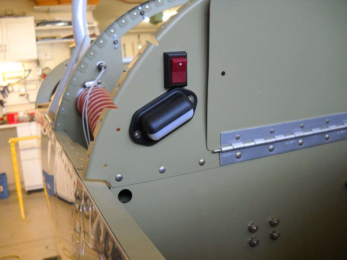
I had seen a cover similar to this on another RV-8, nearly finished, and thought it was a good idea. This view was taken when the fuselage was rolled on its right side, so this is the right wall. The cover will go over some electrical wiring in the recessed area behind it...things like microphone/interphone jacks, aux jack for heated clothing, and lighting control. It is formed to slide up under the part above and then is secured with a few screws.

This will soon enough be my circuit breaker panel, a modification done similar to dozens or hundreds of other RV-8s. Three rows, three electrical busses (main buss, endurance buss, hot battery buss).

Primed and temporarily installed.

And, the baggage door parts primed and ready for assembly. I picked up a cabinet lock that should work for this door for under $5 from Home Depot. Another option is the $39 part from Aircraft Spruce but that is two locks with matching keys. We will see how the cheaper option works out.

I also ordered fuse blocks and wire from B & C Aircraft. Another vendor I expect to be sending a good amount of money toward.
August 20, 2012
In the past two weeks I have worked on the baggage door, the wiring, and the canopy frame mounting. Not as many photos these days since there is more detail work and it doesn't occur to me to photograph some of this stuff.
I clecoed the top forward skins on, filling every hole with a cleco to ensure the best fitting of the baggage door. I then placed the baggage door, with the inner skin just clecoed in place, where it will be installed. The idea is to place it exactly where it will go with a perfect fit at the seams, and then rivet the inside skin into place to hold the exact shape for later installation.
Here is the baggage door held in place with cargo straps.

You hear about the travails of trying to get into the fuselage to pull the rivets on the interior baggage door. However, since my fuselage is still on a rotisserie (the best idea I have copied to date), I simply inverted the fuselage and went in from the bottom (top), leaning over the intervening bulkhead and did the riveting. I won't say it was easy, since it was about 105 degrees in my garage at the time due to the Sacramento summer, but I think it was easier than trying to squirm in on the fuselage floor. Anyways, done is done.

Another view.

As far as the door lock, I did the hardware set up and hoped to use a Home Depot alternative to the $37 Aircraft Spruce lock set but, alas, it did not work out. For whatever reason, the setup is 45 degrees off when using the off-the-shelf cheap lock, and despite me fiddling with it for quite some time, I gave up in the end, returned the Home Depot lock, and put the official Aircraft Spruce lock set on my "wish" list for future purchase. That's not too bad, though, as this set includes two locks, one of which I will probably use on the canopy.
As far as wiring, I did some more tentative wiring including the fuel boost pump, flaps, and ran the nav/strobe shielded wire forward from the tail to where I will install a terminal strip, and also ran shielded wire from the switch locations back to where the terminal strip will go. Slowly coming together as I get the supplies on hand to start the wiring seriously.
As for the canopy, I decided to push forward on the canopy at the expense of riveting the bottom skins of the wings on. I think the warmer temps of the fall will lend itself to canopy trimming so, with that in mind, I built the canopy slide/spacer that mounts on the aft fuselage deck. It, in conjunction with the side rails, allows the canopy frame to slide forward and aft. Built the rail as per the plans which, by the way, are much less explanatory. I eventually figured out the intent but it takes a great deal of study and fitting before cutting or drilling anything.
Canopy rail getting ready for cutting and drilling.

April 2, 2013
As I wrap up the electrical I need to work out the fresh air/hot air vent sources. I need to connect the NACA style scoop to a heater valve. I was going to try scat tube but wanted something a little beefier. I found this 3" connector at Home Depot, held together with two rivets, so it was a fairly straightforward process to remove the rivets and trim it down to meet the 2" OD diameter of my valve assembly (purchased earlier at Aircraft Spruce).
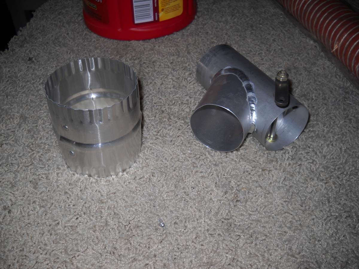
And here is that assembly together. At the edge of the photo on the right is the exit from the firewall hot air valve, and it will connect to the valve in the middle. My plan is to modulate the temperature by using one control cable to close one valve and open the other, and vice versa. I need to make a couple of custom bracket to properly mount the control cable, so that is the next step.
Once these vents are completed, and then that magneto switch is installed, most of the work that I wanted to do before closing up the fuselage will be completed. Before moving to that stage, however, I plan to pressure test the brake lines and fuel lines, and also do some wiring checks.
April 16, 2013
In the last few sessions this past week I wrapped up the fabrication of the electrical system, a major milestone in my mind (anyways), and also did some quality control work prior to closing up the front of the fuselage.
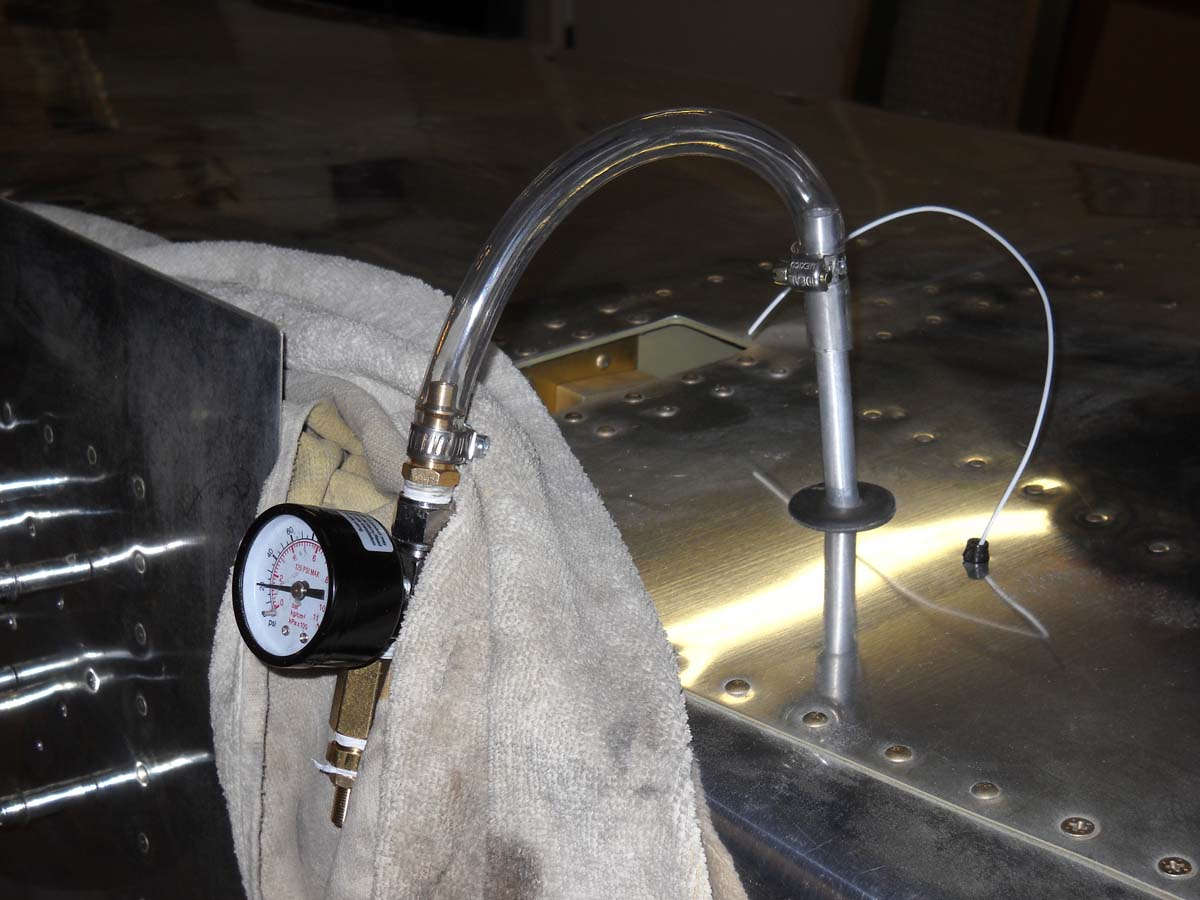
Starting with that quality control work, I pressurized the fuel and brake lines that run in the fuselage, one at a time, to ensure they are leak free. They were not but now they would appear to be.
For the fuel system, I plugged the firewall fitting and then applied a home-made apparatus with a pressure gage and a Schrader valve attached to the fuel lines coming to meet each wing tank and then pressurized the line to 20-25 psi. Eventually all the lines held the pressure.
It was essentially the same process for the brake lines running from the rudder pedals to the point where each of two brake lines exit the bottom of the fuselage on their way to the brake calipers on the wheels (someday, anyways).
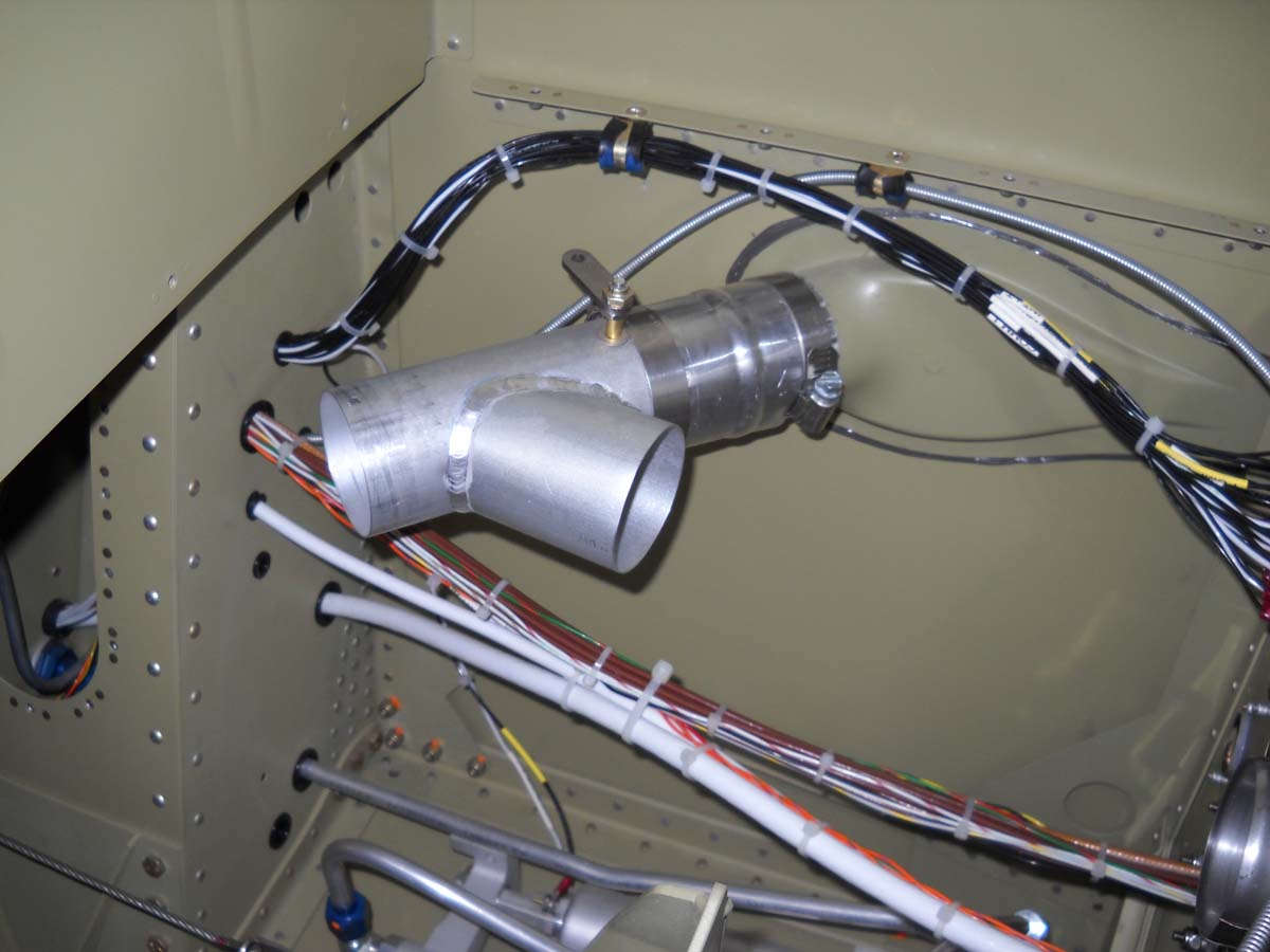
I also installed the air vent lines to supply hot and cold air to the cockpit.
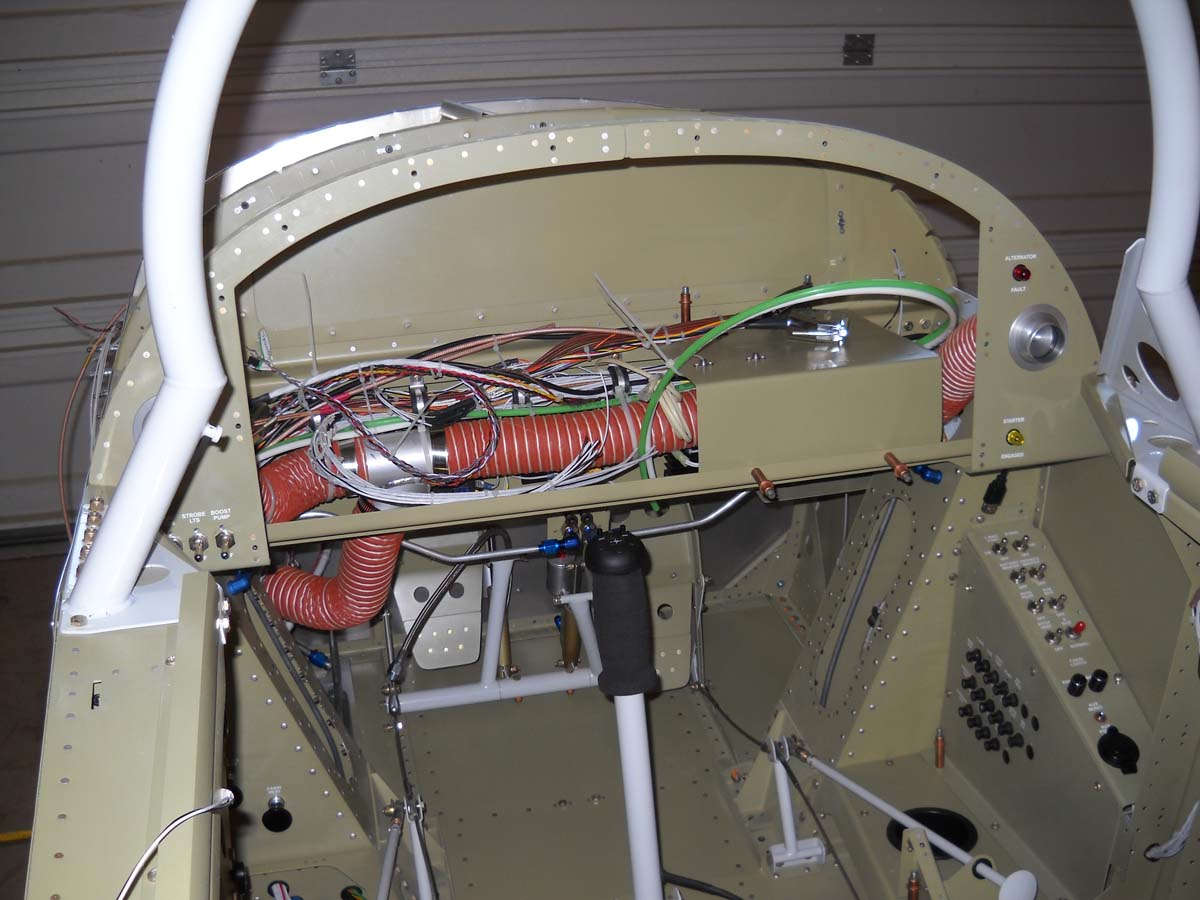
Another view. With these scat lines installed, the behind the panel work is largely completed as far as I can tell, at least until the avionics is installed later.
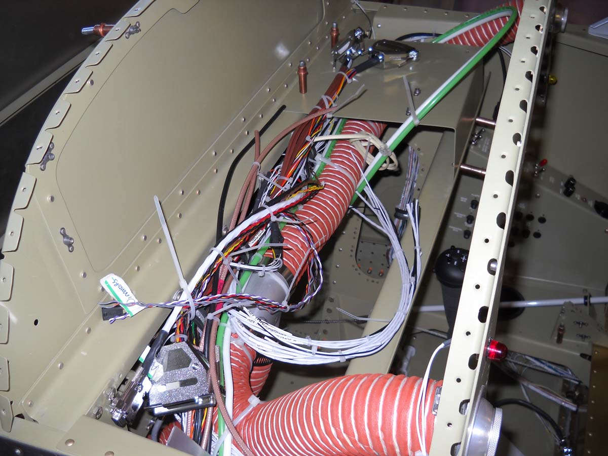
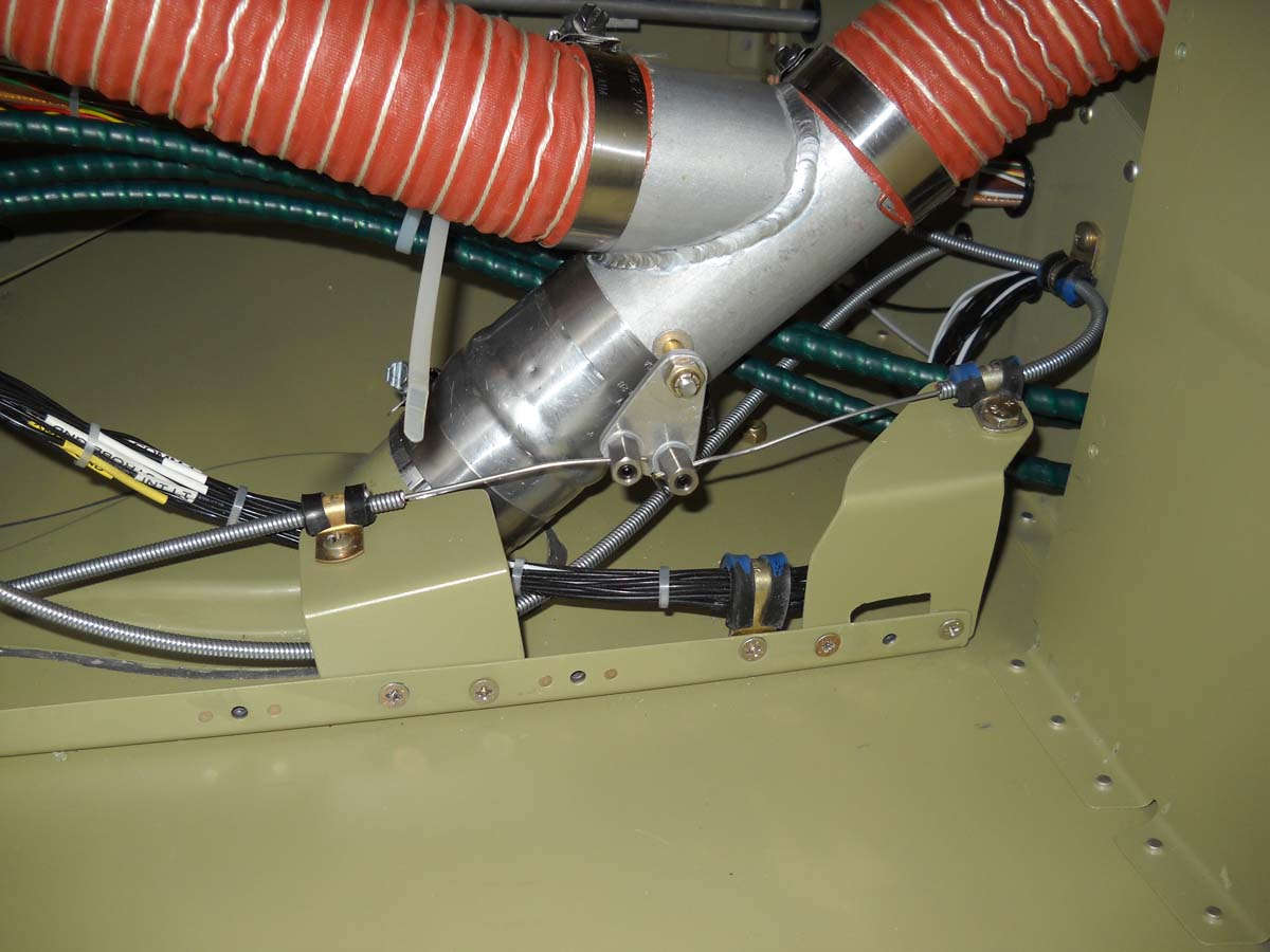
I had planned to use a "Y" tube as a mixing valve to control hot and cold air into the system. I modified the Aircraft Spruce heater valve to take this dual hole fitting that I fabricated to allow a single pull control to a) shift the air source to the cockpit from cold air (from the NACA vent) or hot air (from the heat box off the engine) and b), control the heat box valve mounted on the firewall. After some adjusting and rework, this has proven to be a good installation. Here it is with a bracket holding the control cable; this bracket was later discarded and redone to work better.
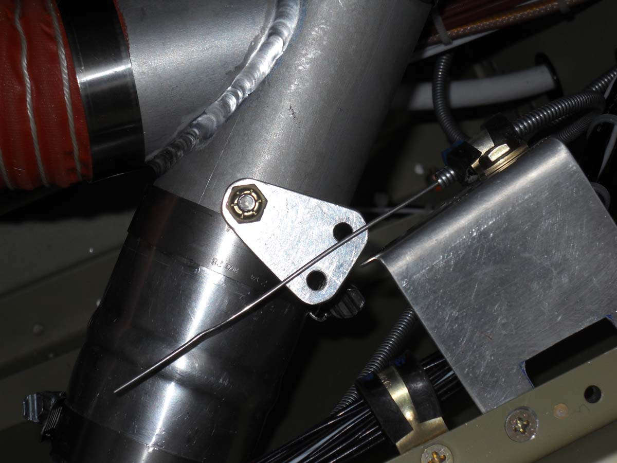
And here is the valve and wiring completed. I needed the cable attach points to pivot so I bought these a-bit-pricey special cable attach fittings to attach the cables to the valve pivot fitting. The cable on the right side is coming from the cockpit; when actuated it will shift the valve from cold air (coming from the fuselage intake) to the firewall heat box. The cable continues toward the left, goes through the firewall, and attaches to that heat box. It might help to orient if you know that the whole fuselage is rotated 90 degrees left so though this appears to be the bottom of the fuselage, it is actually the left side of the forward fuselage.
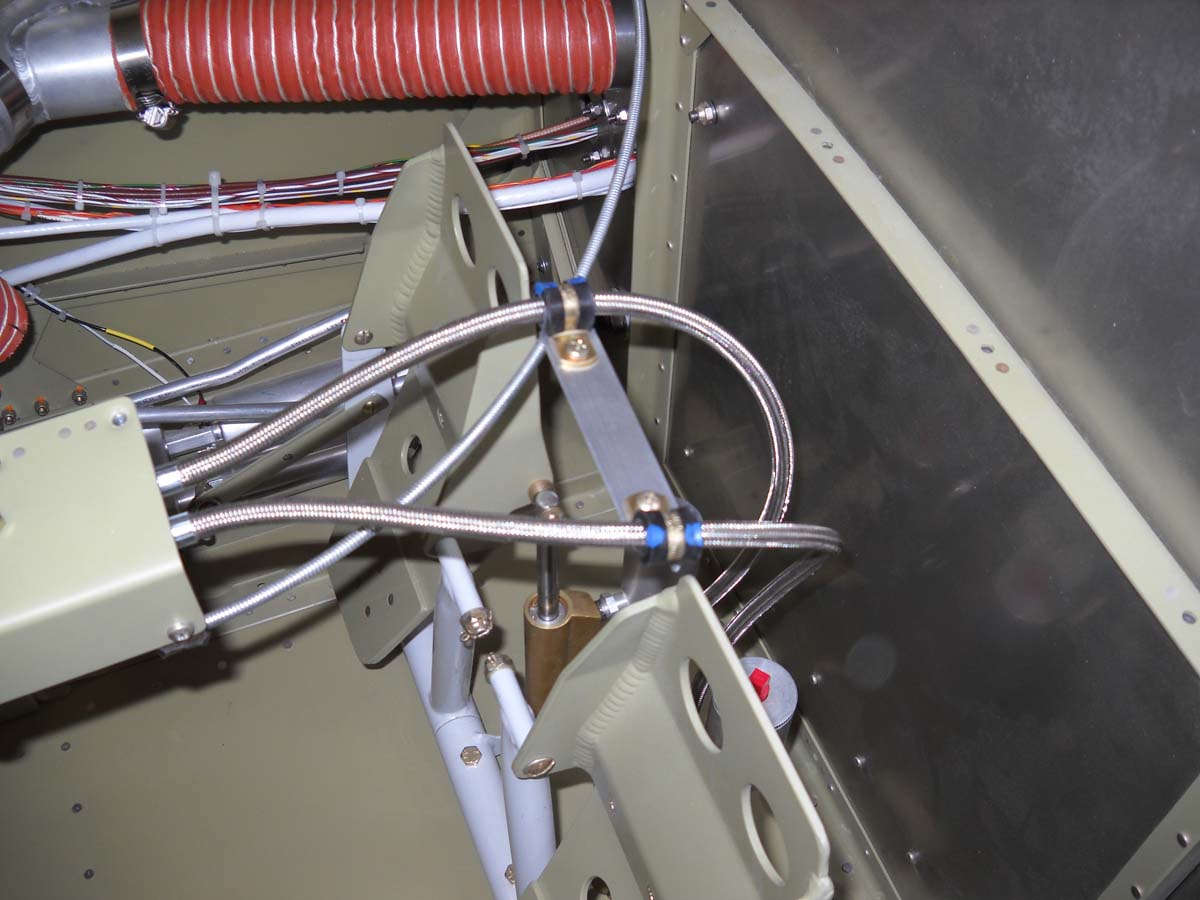
And, after testing the brake lines, I attached them to the master cylinders on each rudder pedal. I was not happy how they interfered with each other when the pedals were moved so I fabricated a piece of angle and two clamps to ensure some separation between the two brake lines. Should work just fine.
I installed the throttle, mixture, and propeller control cables. I decided this should and could be done before attaching the upper fuselage skin and I am glad I did. Inexplicably, the fabricated part that mounts to the throttle quadrant that holds the cables has different spacing than the holes in the gear tower that accepts the control cables. I have no idea how Van's thought that was going to work, but the fix required me to file the holes larger to an oval shape to allow the control cables to penetrate the gear tower. Took three times longer to fit these cables than I thought it would. Not too bad, usually these things take four times longer than I think they will.
The throttle quadrant with the cables being attached.
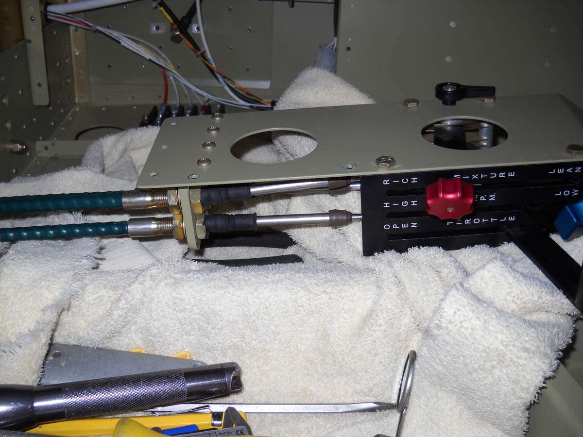
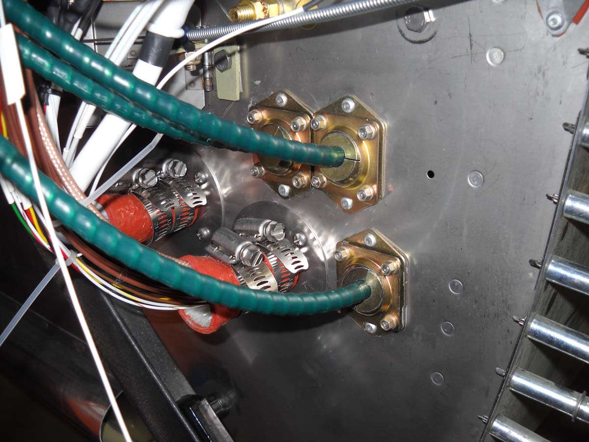
And the firewall pass throughs with the three cables secured. Not tightened down completely yet as that will be done after the engine is hung and the cables put into final position. But, I think, the hard work of mounting these three cables is complete. And, that cable coming across the top of the photo is that heater box control cable that mounts to the heater box valve.
I installed this LED baggage light while I still had good access. It was only later that I realized that this might interfere with the baggage door part that accepts the latch pin. That part mounts in the two holes to the left of the light. We should be able to make it work.
And the back side of that forward baggage area LED light.
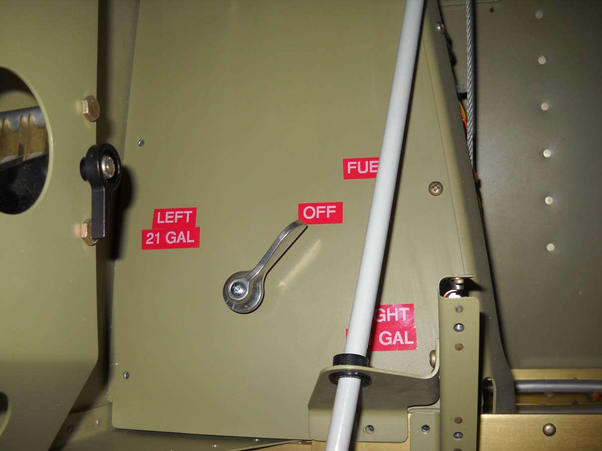
I decided to add the placards to the fuel panel and place it into position. Nothing fancy but it will work just fine. Simple; easy.
I spent an hour or two checking continuity and circuit logic and found more errors than I care to admit to. There were a couple of what I thought were errors also before I figured out that I had to disconnect the 2 AWG battery wire from the starter contactor to isolate the airplane circuits or else they would get power backwards through the wiring. This fact eluded me for a while but after I figured it out the circuits worked pretty much as advertised except for a few glitches, soon enough corrected.
Finally, I thin clecoed on the forward skin in preparation for riveting it into position in the near future.
Another view of the forward fuselage with the upper skin in position.
And, one more.
So, in my mind, I am turning another page in this building project. With the electrical system completed and the forward fuselage closed up, I will turn my attention to attaching the windscreen and doing the fiberglass work for the frame around the windscreen. Something different and, no doubt, more challenges.
April 30, 2013
A major milestone for me this past week as pretty much the last structural rivets were driven to attach the fuselage forward top skin. I called on one of my sons to help me with the riveting, this being Lucas who is handy with his hands and kinds of plods along figuring things out in a pragmatic way like his dad. Not a bad thing when building an airplane and he picked up riveting very quickly. Now I can happily say that all three of my sons have had their hands in this project. So here he is as we are actually riveting the antenna doubler plates on the belly, something else we took care of during that session.
And here is the impressive dude himself. Not sure what to say about this. Don't mess with him, I guess.
And here is a rivet being drilled out. We had one bad rivet on the doubler plates, caused when my bucking bar slipped a bit while he was shooting. Not a big deal; drilled out and replaced.
Okay, and a celebratory moment after we completed the riveting. Cool.
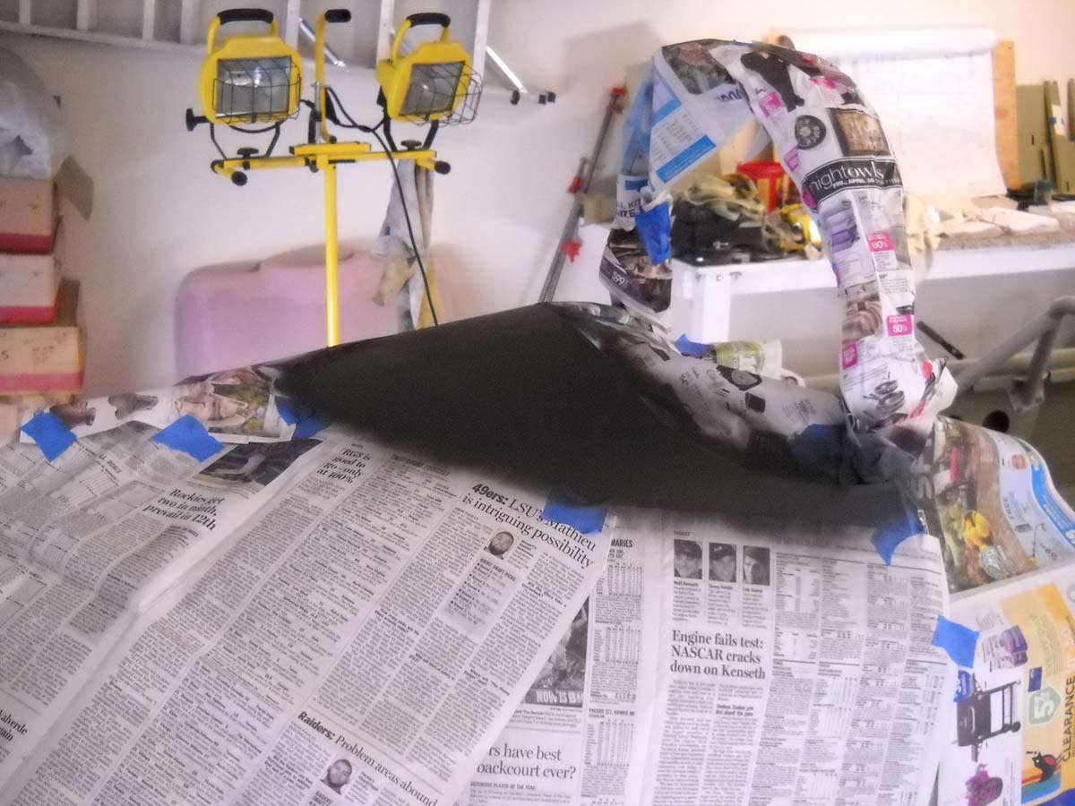
A few days later I moved right into the windscreen work. I read about what to do with the glareshield. Some guys use vinyl to cover the area under the windscreen. Some use carpet. Some go exotic. I went flat black paint. Simple and quick. I think it will suit the theme of the airplane...that is, spartan...just fine. Masked with plain newspaper...a no no in painting books...but handy and effective. A few coats of flat black and done.
As for the sharp metal edge of the glareshield inside the cockpit? Again, I read about some different choices and how you can spend more than a few bucks here. I decided, again, to go spartan and slit a rubber auto hose and fit it on the edge. Looks good to me. I don't think I'll glue it. Seems to stay put on its own and I can remove it if needed to make the panel removal easier.
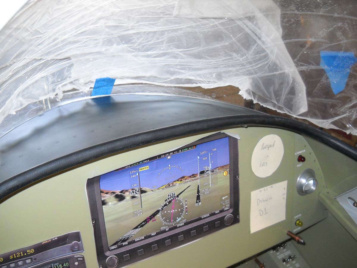
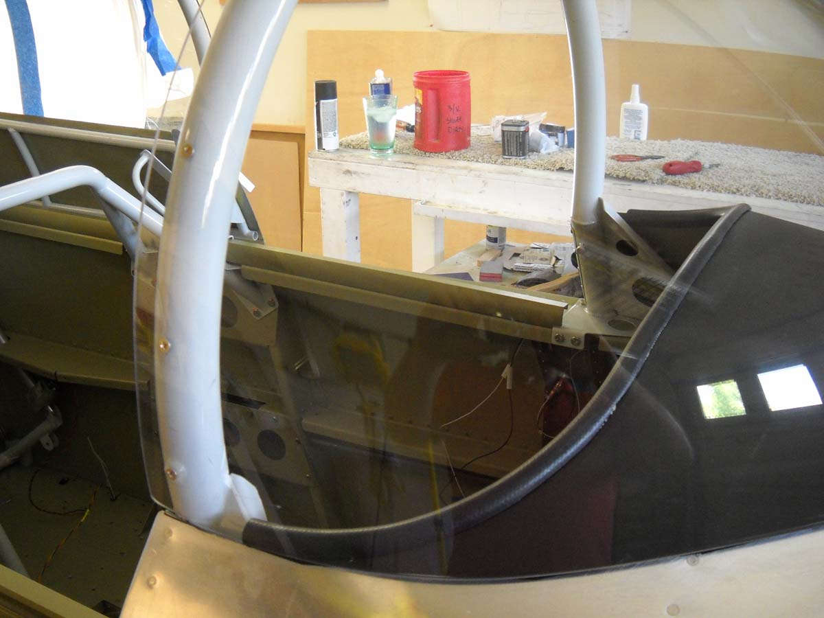
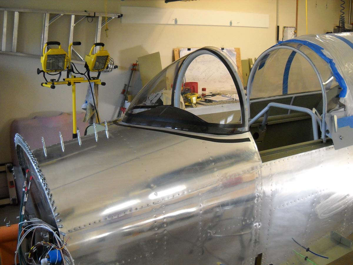
A few from the outside of the completed glareshield work. Flat black paint and the rubber hose. Also, as can be seen here, I have permanently screwed the windscreen to the roll bar. Used spacers on the lower few screws to help the windscreen meet the canopy. Not perfect but a starting point for the windscreen fairing.
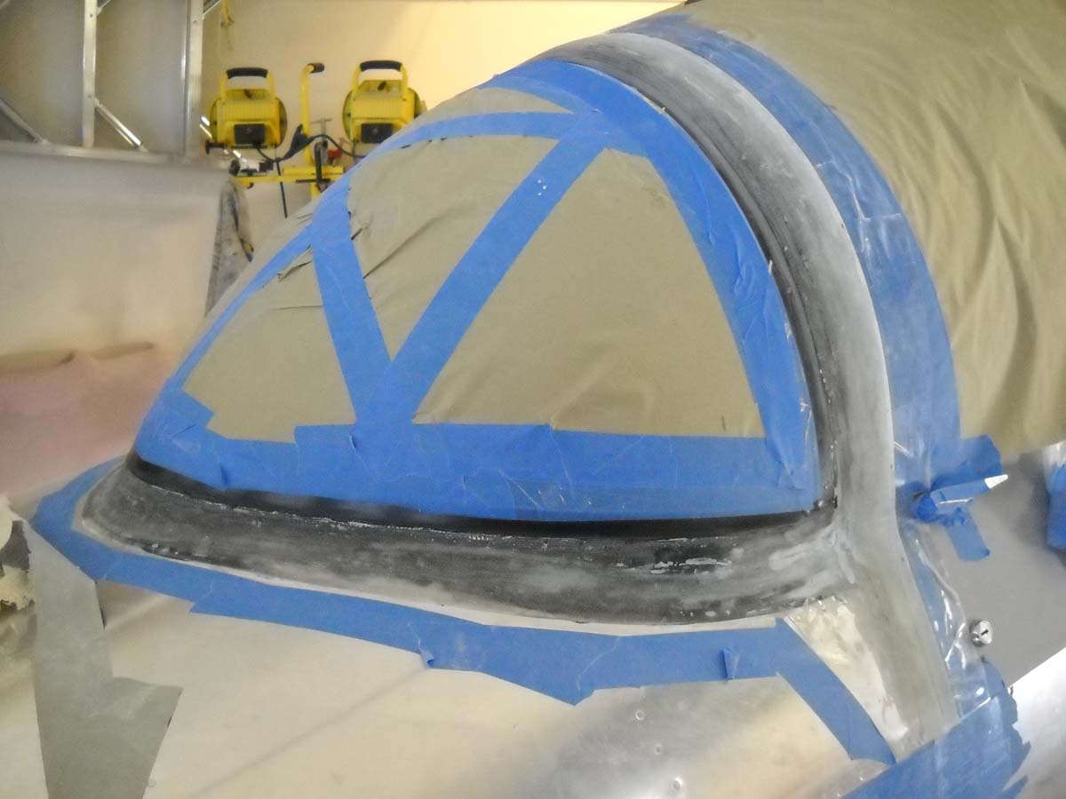
I read about the process of creating the windscreen fairing in numerous sources and pondered it for awhile. Eventually, though, you have to actually do something so I started to lay out the fairing with black electrical tape as per the Van's instructions. Seemed to be straightforward enough.
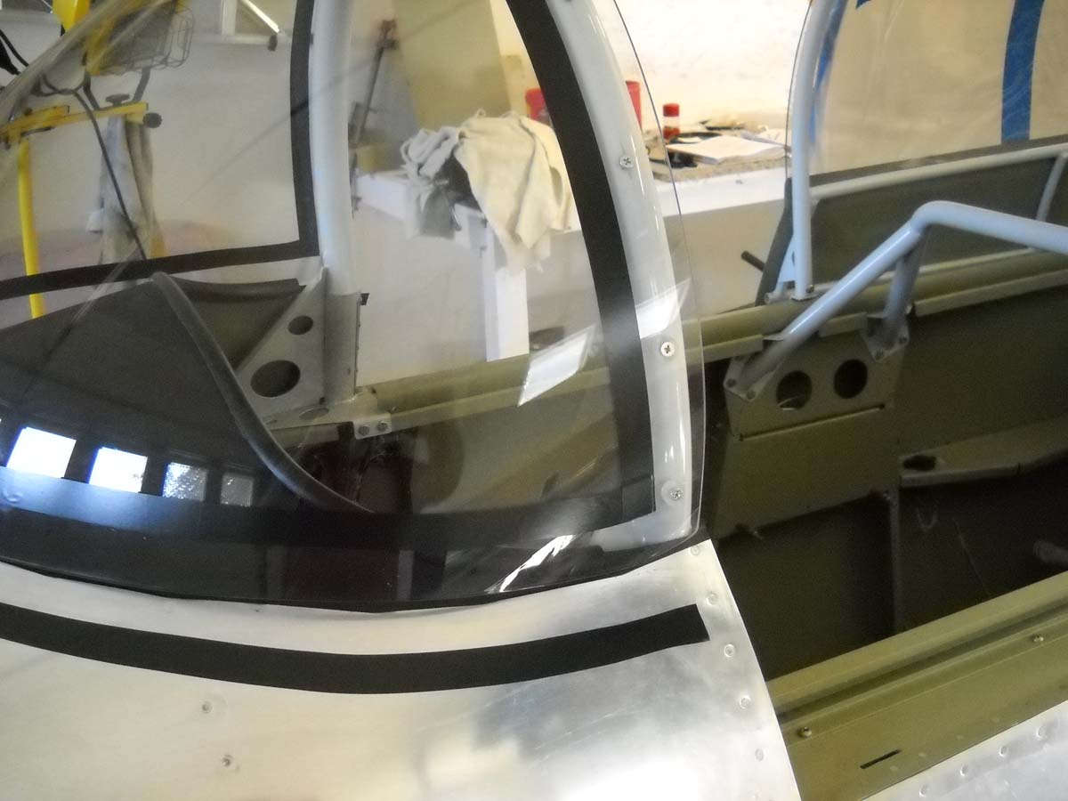
A wider view.
One bit of advice I incorporated was to start with a layer of dyed epoxy as the first layer. This will provide an even and better looking surface to be seen from inside the cockpit looking out. I purchased the dye at Tap Plastics and mixed up a batch and painted it on. I think it will need a second coat for better coverage, and then later will come layers of fiberglass and epoxy laid on top of this, sanded to form the fairing, and then finished with silver paint.
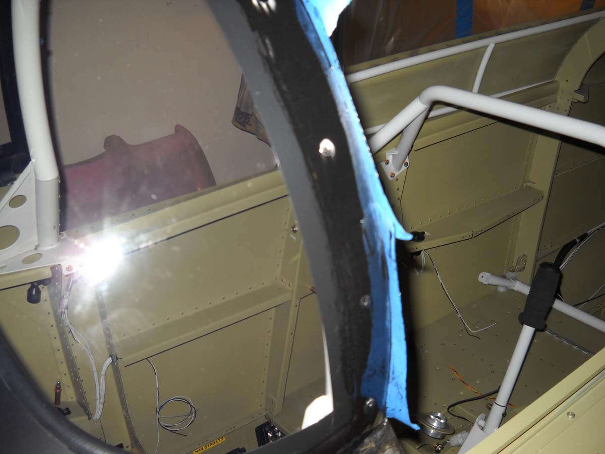
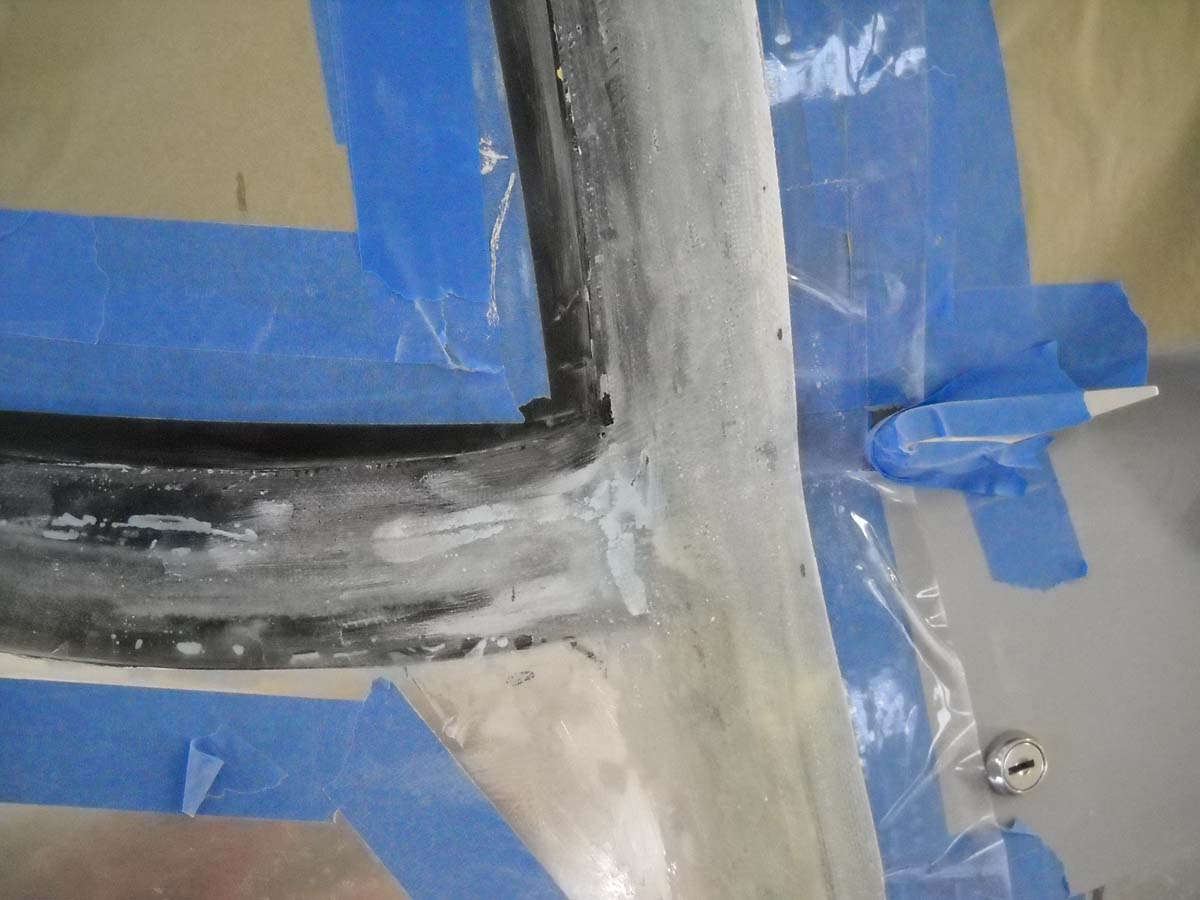
One fly in my ointment is that the left side of the windscreen forward of the rollbar does not lay down well on to the fuselage skin; there is a gap of, maybe, 3/8 of an inch. I thought I might be able to build this up with epoxy and microbubbles but, after trying an initial build up, thought better of it. I ordered some foam that I will use to seal the forward baggage door against rain entry, and use some excess foam, cut to size and epoxied into position, to close the gap and provide a good surface to build the fairing from. We will see how that works out shortly.
May 16, 2013
More work on the windscreen over the past two weeks, here and there anyways as I have been flying for work for part of that time. But I have done the major fiberglass work and am now to the finishing part of the process.
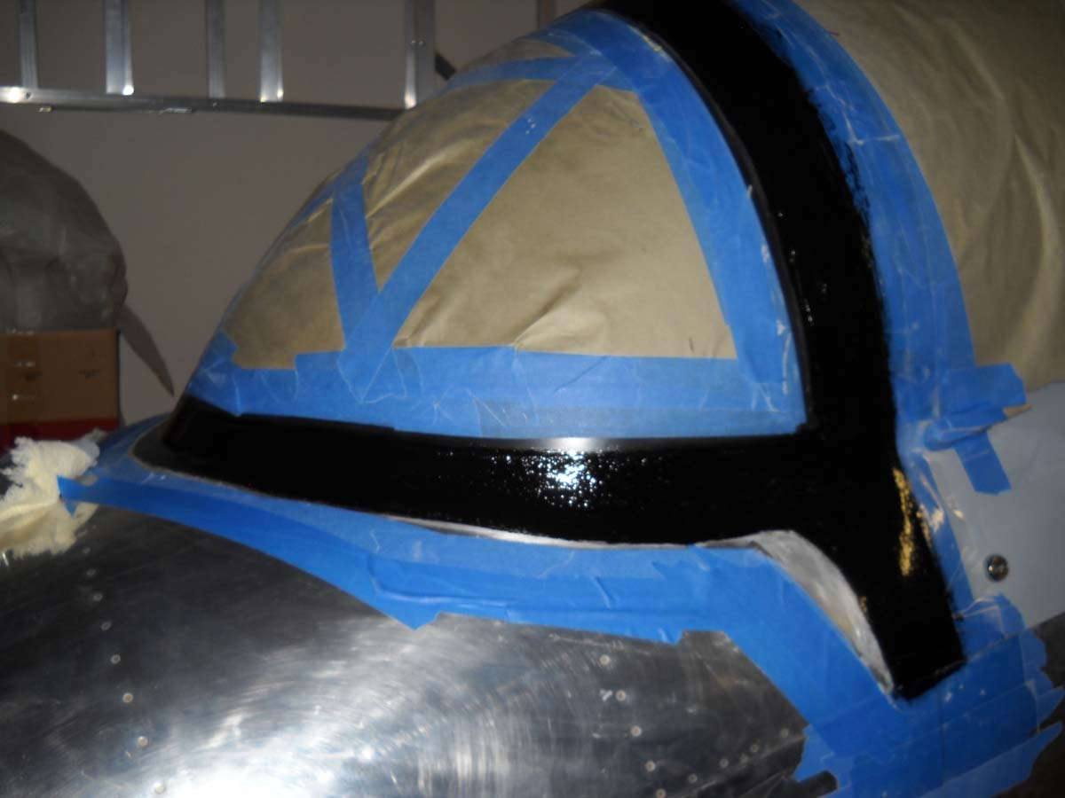
I noted last time that I had a pretty good gap between the windscreen and the fuselage just forward of where it meets the rollbar. I wish I had paid more attention to this area when I was fitting the canopy as this would have made this process easier. Nonetheless, I ordered some closed cell foam from Aircraft Spruce, which I wanted to do anyways to help seal the forward baggage door. I cut and fit a small piece of foam and epoxied it into the gap as a base for filler and that worked about as well as I could hope. I sanded it to flow into the curves. It is noticeable on the inside if you are looking for it, but otherwise the gap filled in nicely and I press on. After I carefully applied two layers of vinyl electrical tape to mask the edge of where the clear plexiglas will begin, I covered the area with two layers of epoxy dyed black. I dyed the epoxy because the view from the inside of the windscreen will be of this expoxy as it lays on the outside of the windscreen, so I wanted it to look better than the clear layer of un-dyed epoxy. Worked fine.
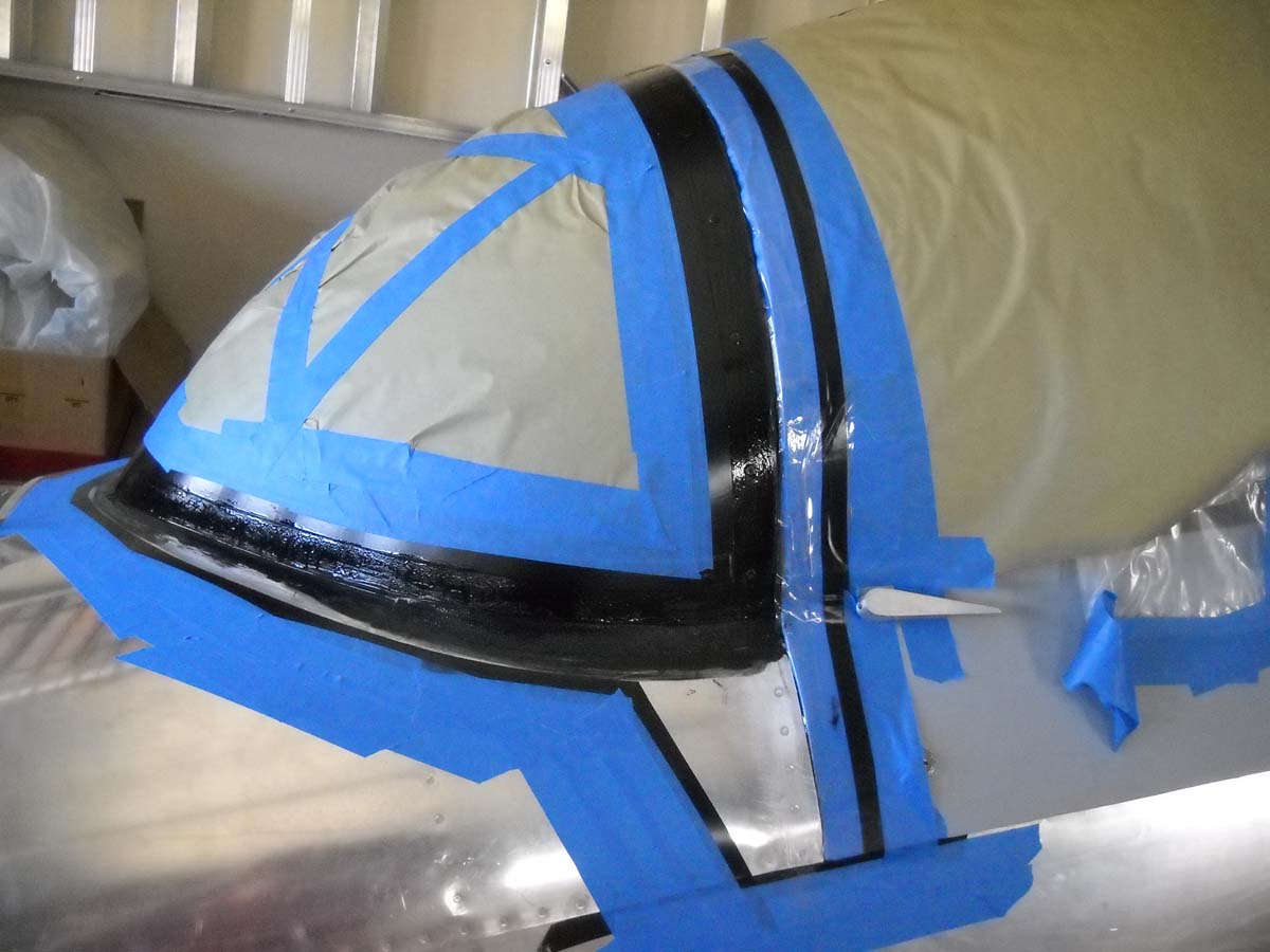
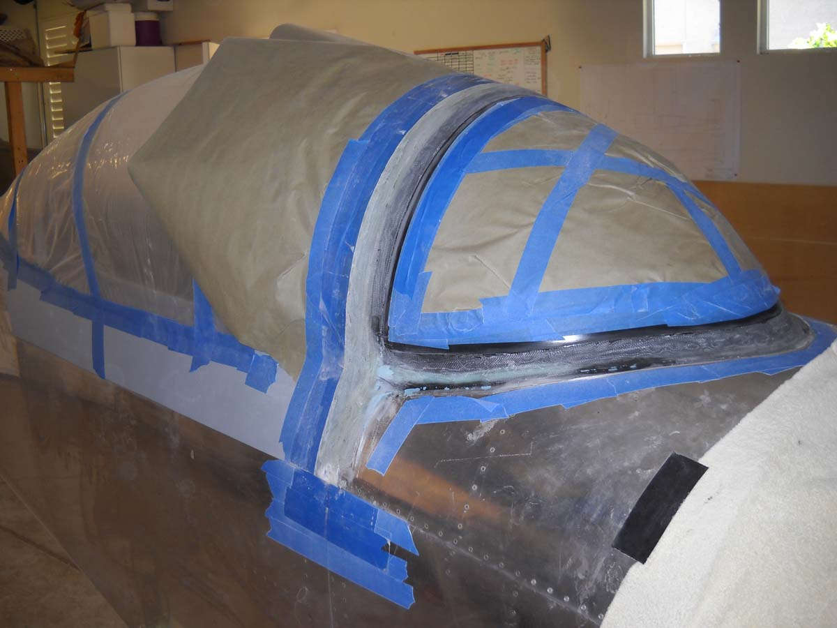
Then, using the basic instructions in the RV-8 plans, I laid up layers of fiberglass. For the fuselage-windscreen joint, I started with a width of 1 inch and increased it with each layer to maybe four inches or so...can't really remember, but enough to bring the fiberglass up to the base of my electrical taped demarcation line. For the area over the roll bar I laid up successive layers that extended from my black electrical tape on the windscreen aft to cover the canopy-windscreen gap and then aft another inch and one half or so. Can't remember that one either. Anyways, it worked out well enough. After sanding a bit I thinned out the canopy layers a bit too much and added another two or three layers of fiberglass there to fill it in a bit.
This looks to be a mess but actually is not too much. I tried to make a nice curve where the windscreen fairing changes from vertical to horizontal, and also where it widens out to meet the width of the canopy to cover the gap. A couple of compound curves here that took some work. This is a photo from the middle of that work. I'm no fiberglass expert but one thing I figured out is that most errors can be readily fixed.
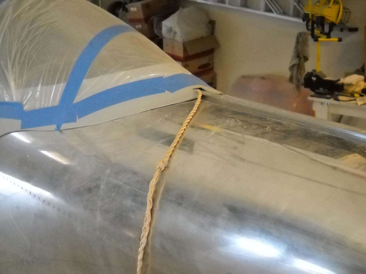
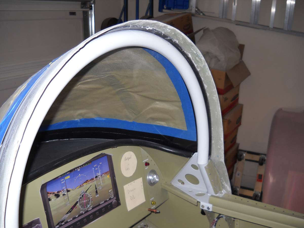
Another view after most of the rough sanding was completed. At this point I was not quite sure what I had for the windscreen-canopy thickness so I went ahead and worked the canopy so it would open for a check.
This rope idea borrowed from somewhere is essential in the process as far as I can tell. I am not sure what I would have done without this rope attached to the inside of the canopy frame to help me get it open.
After trimming and a bit of sanding, this is how the fiberglass over the roll bar is shaping up.
I did some more fine sanding to get the shape to where I wanted it and then covered the fiberglass with a layer of dyed epoxy. The next step is to sand this off as part of the finishing process.
I will do this several times to fill in the imperfections and get the fairing to just about the final condition. Eventually, coats of filler prime will be sprayed to make sure the imperfections are gone.
So, a few more sessions with the windscreen and this part will be nearing completion. The next big chore after this will be polishing the exterior. I am shortly to order material from Nuvite to move into this area. I expect dozens of hours of work to polish the aluminum, but that's okay. A labor of love, as it were.
And, by the way, I jumped in to reserve a registration number for my RV-8. Henceforth, it will be known as N9324Z. Why this number? Well, in one of my other lives I am a B-17 historian, and I decided early on that this RV-8 would carry a discarded B-17 registration forward. The chosen registration was once carried by B-17G 44-83542 which, in its civilian life, was an air tanker operated by Aero Union at Chico, California. It was badly damaged in an accident many years ago and its registration was eventually cancelled. The airframe lives on as a museum display at the Fantasy of Flight museum in Florida. The registration number? It will live on marked on my RV-8.
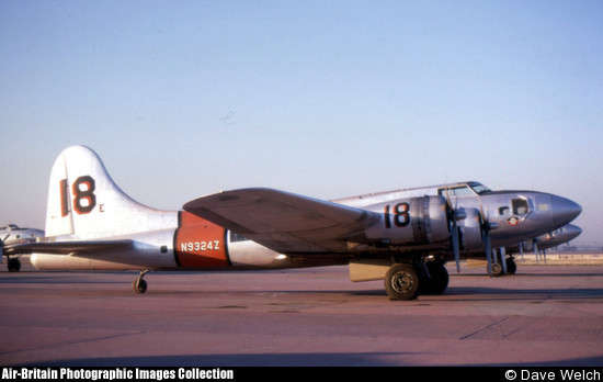
I have a bunch of photos of this airplane in my files, but not near me as I write this. Dave Welch took this nice photo of
May 31, 2013
Well, the gist of it is that I pretty much finished up the windscreen during the past two weeks. I am satisfied with the end result and think it turned out pretty well and meets my own standard, which may or may not actually mean a whole lot. Nonetheless, I think it's going to work just fine.
Obviously, this process is a whole bunch of sanding and applying a new layer to be sanded off once again, mostly epoxy but a bit of filler here and there. Once I was pretty well satisfied I sprayed some filler primer on and worked some more to get the final surface very close.
I then turned my attention to the inside surface behind the roll bar. It was pretty rough, not only in surface but also appearance. I sanded it smoother and added some filler to even the surface out a bit better. When it was what I wanted, I masked the interior so I could prime and then paint this surface.
I've come to the conclusion that anyone who builds one of these airplane without a rotisserie is working harder than they need to. It has proven invaluable countless times to be able to rotate the fuselage around for better access and a more comfortable work experience. This was no exception.
The unveiling was a bit nerve-wracking, not knowing what I was going to find underneath the electrical tape, masking tape, and paper. This was it. I had a bit of edge clean up here and there and maybe a flaw or two or three, but I will never tell. Looks pretty good to me and just about as good in person.
A view with the canopy cleaned up a bit and rolled closed. There are different ways to make this canopy fit with the windscreen but I am quite happy with this one, which I think is basically stock. I guess I am too.
A summary view of the fuselage as it now stands, which is pretty much complete. There are a few odds and ends: flap positioning sensor and the odd such thing, but firewall aft is essentially done on this RV-8.
Next up: I'm going to become a metal polisher next and will start, I think, with the underside of the fuselage. I'd like to get the fuselage polished first so I can do some paint work on the windscreen and canopy, and also get the landing gear legs mounted. A few months out and this fuselage will lose the rotisserie (okay, a Harbor Freight engine stand) and stand on its gear for the first time. Maybe not wheels and tires, but up on its gear. Cool.
November 12, 2013
Did work on the landing gear and made some good progress. Basically, the landing gear was mounted and bolted into place, then the fuselage was rolled and set on its new landing gear. I added the tailwheel and removed the engine stand from the firewall. This was substantial visible progress, even though it remains three steps forward and two back sometimes.
Here is my son Lucas doing some preparation work prior to mounting the left gear leg. Having a second set of hands definitely makes things much easier when installing these gear bolts.
There are five bolts that hold each gear leg in place, two outboard and three inboard. The two outboard ones are reached through the gear towers and can be hard to get to.
Through research and seeing what others have done, I became a bit concerned about perceived weakness of the standard nuts supplied in the Van's kit to hold the outboard gear leg mount. The bolts are close tolerance NAS6206-27 bolts with hardened washers, and the standard nuts are supposed to be NAS679A6, though the ones that came with my kit appeared to actually be MS21042-6s. In any event, the provided bolts are, for lack of a better term, low profile nuts about 2/3 of the vertical height of a normal nut and therefore has fewer threads that engage the bolts. This has concerned some builders and there appear to be some documented failures and/or loosened nuts of these critical fasteners. Much stress is transmitted to these two bolts/nuts, particularly with forward and aft stresses.
Trying to preclude potential problems, I purchased four NAS1804-6 nuts that are considerably stronger and are full-sized nuts, therefore engaging more of the bolt threads. Here is one of the nuts inside the gear tower after the installation and applying 240 inch pounds of torque.
I confess I may have a problem in that I do not have a thread exposed through the top of the nut. The higher profile nut, it turns out (and not really surprisingly), may need a longer bolt, so I am not necessarily done with this nut/bolt combination. I have a bit more research to do to decide on buying four NAS6206-28 bolts that would give me another 1/16" in length. More to follow here.
All that aside, I will mention that these two Snap-On tools, the extension and particularly the swivel socket (7/16" in size) proved to be incredibly helpful in tightening the hard to reach nuts inside the gear tower (thanks to Greg and his tool box). This swivel socket uses a 1/4" drive and is small enough to maneuver into position and will hold the nut through that maneuvering to allow the nut to engage the threads, and then to properly torque the nut. Each of the two nuts are slowly torqued down (the book says alternate tightening the nuts in 5 inch-pound increments to reach the 240 inch-pound value) so being able to switch the socket back and forth between the two nuts is invaluable.
So, I enlisted fellow RV (RV-7, actually) builder John to come over and help me jack up the fuselage using a Harbor Freight engine hoist, and roll it over to put it up on its main landing gear. Worked out quite well. Thanks to John for the extra set of hands.
And here is one of my modified Harbor Freight moving carts that will serve as a temporary rolling gear. I later added zip ties to hold the gear mostly in place. What could go wrong? They are nylon.
And, here is the tailwheel assembled and attached to the aft fuselage. Should be a permanent installation here. No need to rework or add work here.
So, here is the end product. The RV-8 fuselage is on its gear pretty much in the attitude it will have henceforth. Looks pretty good to me. I added the canopy for aesthetics and for test purposes.
Well, the test purposes was to sit in the fuselage for the first time, really, with the whole thing pretty much configured as it will be when I fly it. Ergonomics, how well do I fit, visibility, engine noises, etc. Fit pretty good. I can't wait to fly this thing, but I have to wait. Engine and avionics. And money.
November 30, 2013
Not too much in the past few weeks. However, I've done a bit of final wiring in the fuselage. I had previously wired two convenience lights, one in the forward baggage compartment and one in the aft. They are wired to the hot battery bus so the battery master switch does not need to be on for them to work. I had made provisions for a similar cockpit light and completed the wiring on this yesterday. Basically a simple LED light, a Radio Shack push button switch, and a Molex connector. I added the connector because of how the light is mounted. I can disconnect if need be.
January 2, 2014
An update here that really covers the minimal progress that occurred in December 2013, but here it is 2014 so there you go. I don't think anyone is really reading this so it won't much matter if I do a crossover on the years.
I completed the tail strobe/light mount that will be affixed to the bottom fiberglass rudder cap. I could have purchased something similar for less than $20 but what I fabricated is as good or better. This aluminum mount will be riveted to the fiberglass and the light fixture will then be screwed to the mount.
Over the past week or two I polished the vertical stabilizer and both elevators, so those were looking good. The intent here was for me to assemble the tail components and do some wiring, rigging, and adjusting. I'd like to get all this finalized as if I were to be flying the airplane sooner than later. It will all come apart once more and put into storage, but when I do the final assembly in a year or two, all these little tasks will be completed.
So, here is the tail being assembled on the fuselage.
And, here it is with the elevators and rudder mounted. I plan on wiring the tail light fixture with a connector, and also the electric trim with a connector. The elevators and rudders will be adjusted for proper distance from the stabilizers, and the elevator push tubes will be assembled in place and adjusted for flight. The bottom rudder cap will also need to be drilled and nut plates added to the rudder for the final assembly.
Once disassembled, the components will be stored but the fiberglass empennage tips will be set aside for painting (silver) and the rudder set aside for painting (red, white, and blue). All this work will take a month or two, depending upon how much time I can devote. After this work is done, back to the wings.
January 24, 2014
Progress continues on doing final fitting items on the empennage. Over the past weeks I did the following items:
Well, the first challenge is to wire the Suntail in as suggested by AeroLeds. Not difficult but I want to minimize or eliminate any interference with the comm radio audio so I read and followed. Essentially, I grounded the Suntail black wire to the fabricated mounting plate I installed earlier, and then grounded that to the airframe at the rib on the bottom of the rudder. (Not sure the Suntail case still needs to be grounded, theories vary and I never sought the final answer, but I did it anyways.) Then, I prepped the shielded wires coming from the front of the fuselage and connected the three wires (power for strobe, power for position light, and synchronizing wire) to the Suntail, and then, using the wire shielding as the ground return, grounded the shield (using a solder sleeve pigtail) to the same ground on the bottom rib of the rudder that I used for the case/Suntail ground. Some guys ground at the airframe in the tail section by running a ground wire forward but I decided, with pretty much no credible electrical experience to draw upon, that the three �rudder to vertical stabilizer� metal attachments with three rod bearings and nuts and bolts and rivets all working together should provide an adequate ground connection with the rest of the airframe. I�d rather minimize the length of unshielded wire carrying any current to minimize audio interference.
But, when I powered it all up, I hit a snag. Actually, two snags. The position light worked when I turned on the strobe switch. When I turned on the position light switch nothing worked except that the fuse for the strobes blew. Repeatedly. Hmmm. So, I did a bit of initial troubleshooting and found nothing, then removed the floor panels to reveal the terminal block I had installed adjacent to the right rear seat footwell. The first problem was easily rectified as I had wired the strobes and position light power wires backwards. Corrected that problem so the position light turned on with the switch. The strobes also worked well, at least until I put the floor panel back in. Then the fuse blew again. Well, the answer became obvious that the floor panel was causing a short.
I knew it was tight in there but when I took a closer look I determined that the problem was the little metal jumper connection that joined two adjacent sections of the terminal block was grounding against the side of the footwell.
Since these jumpers �jump� over the insulated separators of the terminal block, the raised metal jumper is exposed and grounded to the footwell when it was in position. Not good but not hard to fix either. The solution was to fabricate three little jumper wire connections to replace the metal jumpers. The jumper wires are well clear of any interference and the resulting wiring checked out fine. Strobes and/or position lights mounted on the rudder now work well and as advertised. My initial take on the AeroLeds is that they are an excellent aviation grade LED lighting system. As advertised and as I wanted. You get what you pay for, usually, and in this case, yes.
My next task will be to determine how to attach the bottom rudder fiberglass part to the rudder. I was going to add nutplates and screws but now think I will as per the plans and use pulled rivets. Couple reasons for this: Once assembled I should not need to get the bottom cover off; the bottom cover cannot be removed without removing the rudder because the tail wheel assembly does not allow sufficient clearance; and it will be a chore to partially remove the cover to disconnect the Suntail wiring, then remove the rudder, so it won�t be much more to drill out the pulled rivets. All that to say that once it is together I expect it will stay together. Pulled rivets it is, then.
After that is done, I plan to cut and fit the fiberglass fairing that covers the horizontal and vertical stabilizer joint area. Complete that fairing and prep it for paint so that when it all comes back together later, it will be straightforward to complete. Should be able to get to all this in the next few weeks.
I also ordered my seats from Classic Aero. I decided up the Sportsman style using the ultraleather material. I almost went genuine leather, but decided the ultraleather was a better option for me. Luke at Classic Aero was very helpful and I can expect to see these seats long about April.
February 7, 2014
I have been in Dallas this past week doing a bit of simulator refresher in the Lear 60, so have not been working on the airplane. Well, actually, I completed a CAD drawing of the electrical system, and that took a bit of time since I had to learn to work with Turbocad. The drawing turned out quite nicely. I need to do a final edit on it before posting it here, but it should work to continue to document the electrical system with CAD drawings.
As far as actual work on the airplane, last week I spent some time on the empennage fairings, both upper and lower. The upper is shown here in place:
It actually fits pretty well in my estimation. I need to correct two areas to make it lie flat, but other than that it won't take much to get it ready to be prepped for primer and eventual paint. I also drilled the attachment holes and will have to add nutplates to the horizontal and vertical stabilizers to hold this fairing in position.
For the lower fairing, I think I will just use the Vans-provided metal fairings. Some guys have had problems here but I think the provided ones will work fine. Each side of the fuselage has a small metal fairing with a rubber gap seal on the top that is screwed to holes already drilled in the fuselage. These holes need to be tapped for #6 screws, something I will do in my next session.
I've been scratching my head a bit over one of the great RV-8 dilemmas: where to mount the ELT antenna. For those unfamiliar, the ELT is the Emergency Locator Transmitter required by the FAA to help locate a downed aircraft. It transmits a signal used by search and rescue and greatly aids in locating a missing aircraft. For the RV-8, the problem basically is that there is very little suitable surface on the aft fuselage to mount the ELT antenna as specified by the installation instructions of most ELT makers, primarily due to the sliding RV-8 canopy. Builders basically have these choices: bury it beneath the empennage fairing with it mounted horizontally; mount it on the fuselage forward of the windscreen; mount it on a wingtip; mount it on the tip of the vertical stabilizer; mount it on the lower aft fuselage; mount it in cockpit under the canopy but out of the way of the pilot or passenger; or, fit it in the tiny amount of real estate available between the empennage and the canopy when it is open. None of these options are ideal and none meet the installations instructions 100%. For me, I had decided early on to use the ACK E-04 121.5/406 mhz ELT. The 121.5/406 mhz antenna is longer and limits choices a bit because it will not fit under the empennage fairing. I am not fond of mounting it on the wing tip or the vertical stabilizer tip (vulnerable) or on the forward fuselage or lower fuselage, so it pretty much leaves me with the aft fuselage between the canopy and empennage fairing. It won't be real pretty, which is why it is avoided. But, it will be functional and, for me, comes closest to meet the installation requirements put out by ACK for the unit.
As part of this process, I mocked up the ACK 121.5/406 mhz antenna just to get a feel of where I might be able to mount it, and it helped me verify the decision I had pretty much already made. Costly components to construct the mock-up: two coat hangers.
Because I need to get this antenna mount finalized, probably on a doubler plate, I went ahead and ordered the ELT. I should be able to complete the installation in the next few sessions and move on to the next thing. After the antenna mount is installed, I can do a bit of final riveting on the little bulkhead between the horizontal stabilizer and the fuselage. Okay then.
February 18, 2014
I fear I have crossed over to the dark side in the placement of my ELT antenna, installing it, of all places, not only in the slipstream but also in accordance with the manufacturer's requirements. I have fallen into the clearly obvious FAA electromagnetic conspiracy of having ELT antennas mounted where they might work. Oh, well, that is homebuilding.
So, for this ACK 121.5/406 mhz antenna, I decided a doubler plate was required and fabricated said doubler, and attached said doubler with rivets.
And here is the antenna mounted from the outside.
And here is the antenna mounted from the inside.
On to other items, in this case tapping for the attachment screws to hold the lower empennage fairings into place.
And, for the upper empennage fairing, I did a bit of fiberglass work to allow the fairing to fit better against the horizontal stabilizer. It was a bit wavy but after applying some glass and cloth to the mating surface, it should work just fine with sanding and final prep work.
Also seen here is that offensive ELT mounted there mocking me.
In my idle moments, I also fitted the mounting straps for the ACK E-04 ELT on the mounting plate. The connections for the ELT in the aft fuselage are already wired. This mounting plate will also hold the Dynon transponder later.
And that's it for now.
I've spent the past few weeks working on finishing up the odds and ends of the empennage and aft fuselage. This included doing the empennage fairings, completing the wiring on the elevator electric trim, and doing a control rigging of the elevator and rudder. However, in the midst of all of this, Van's released two service bulletins, SB 14-01-31 and SB 14-02-05. The first one is for a spar doubler for the horizontal stabilizer, and the second adds some reinforcement to the elevator rod-end bearing attachment points. The latter one is not applicable to me because the airplane is not yet flying and applies only if cracking is found during inspections.
However, SB 14-01-31 is applicable as it adds two doubler plates to the middle section of the horizontal stabilizer front spar to prevent cracking of the spar web, or to prevent any cracks that might form from becoming a structural problem. To complete the service bulletin, the inner ribs, front and back, need to be removed as do the spar reinforcing angle and spar splice angle. The spar web has some notches added to stop any cracks, the spar flanges are trimmed, and then new doubler plates are fitted and riveted into position.
This service bulletin caused a bunch of consternation on the VAF forum site, but in the end the application is straightforward, especially if the instructions are followed (see below). The actual completion of the service bulletin is somewhat optional if an airplane is not yet flying, but Van's recommends it be completed on all applicable models, so I decided to go ahead and get it done.
Re-constructed a stand to hold the horizontal stabilizer. Had one years ago but it is gone.
There are a whole bunch of rivets, both skin to rib and spar angles to spar web, that need to be drilled out to start the process. The technique I used was to use a #40 drill and go into the top of the rivet far enough to follow with a punch that, with some leverage, will pop the top of the rivet off. Then, I used a spring-loaded punch backed by a bucking bar to drive the tail of the rivet out. Works great about 95% of the time. That other 5% can be a bugger, though. In any event, I drilled out all the required rivets over two sessions of about an hour each. Damaged one or two holes in the process but not show stoppers by any means. I can find other ways to damage the holes, anyways (see below).
Next, I added four notches, two top and two bottom, in the spar web where the two inboard ribs meet the spar web. This is where the cracks were developing and, from what I can tell, the original RV-7 instructions specified that these notches be added but nothing is mentioned about them in the original RV-8 instructions. A close look at the original plan drawings for the spar show the notches but nowhere in the plans does it instruct a builder to add them. (The drawings are the same for the RV-7 and RV-8 as the parts are common.) So, the service bulletin instructs to look for the notches and if they are not present, to add them. I added them. For a flying airplane, if cracks are found and you are lucky, filing material away to create the notches can also remove small cracks. I guess the notches are a stress relief thing but I did not feel much stress relief when I filed out the four notches in the tight working area.
Next, the upper and lower inboard flanges on the front spar are trimmed at an angle, also a stress relief thing. To do this, Van's supplies a small piece of stainless steel in the SB Kit ($15 plus $5 shipping from your nearest Van's mailbox) that is inserted between the skin and offending spar flange to reduce the chance of damaging the skin when Dremel trimming. To improved access, I removed the four inboard skin to spar flange rivets on top and bottom, both sides, to further push the skin away from the flange, and this seemed to help. All four flange trims were accomplished with a bit of time but little problem. This, then, completed the front spar preparatory work.
So, the two doublers are then prepped and fitted into position. The Van's instructions are specific on drilling for the rivets, so I dutifully followed along. A 90-degree angle drill makes all the difference and was working just fine. But, alas, I had read on a VAF posting about a technique of drilling the four outboard holes on the doublers (into the reinforcing angle and the splice angle) in assembly on the workbench instead of trying to drill it inside the horizontal stabilizer. Okay, I thought, that makes sense, and used that technique. Fitted it back together on my workbench, clecoed securely, and drilled away.
Well, this technique did not work for me. I have yet to figure out why it did not, but though the existing holes in the angles were used to match drill the doublers, when I reassembled the thing on the spar web, I had serious misalignment issues not only with several of the four outboard holes on each one but also several of the other holes on the angles. I tried all sorts of combinations of how I could have misaligned them and studied photos I took of the process, but cannot figure it out. Everything lines up on my workbench but not when attached to the spar. Scratch my head and curse my deviation from the instructions because, as it turned out later, drilling in assembly inside the horizontal stabilizer was a non-event. Instead, I made the whole thing three times harder, more complicated, and with not as good a result. All from my thinking "that sounds like a good idea." Not that there are not good ideas out there, but this one did not work for me. Your results may vary. I hope so.
So, I was left at staring at two doublers with holes that did not line up. Plus a few holes on the spar that were slightly misaligned from their corresponding holes on the reinforcing and splice angles. I was going to order another SB kit ($15 plus $5 shipping from your nearest Van's mailbox) but decided, instead, to try fabricating the two doublers myself from some 0.064 scrap aluminum (same as the originals). An hour or two later I had two exact duplicates of the doublers in my hand. Turned out quite well in my opinion, but that's just me.
I match drilled one hole from the old doubler to the new one, then clecoed it into position. I then laboriously redrilled all the matching holes from the angle and spar side into the doubler, and then did this again for the other doubler. It worked out just fine but I was a bit apprehensive at removing the freshly drilled doublers from the spar to deburr and clean everything up, because I knew I was going to have a few holes that were "ovalized" from the earlier misaligned drilling. And I did have a few, but it was not as bad as I thought it was going to be. Not very pretty, as it should have been, and still a mystery in my mind as to why the misalignment occurred in the first place.
So, after doing the final prep work on the doublers, I riveted them into place. A few of these rivets can be squeezed, but most are bucked. Not real difficult as access on the center rivets is easy, and even the rivets on the inside of the wings are pretty easy with the offset rivet set. The norm is to have the manufactured head of the rivet on the thinner material if possible, and this works for most of the rivets but a few I had to set the other way due to the space available for the rivet gun. Nonetheless, straightforward riveting. I over drove a few; out of practice, I guess.
Then, I prepared the two angles that are used to attach the main ribs to the spar, to replace the original flanges removed to make room for the doublers. I neglected to take photos of this part, but the angles are riveted to the old main ribs, and then that assembly is riveted back to the spars. Then, the main ribs and nose ribs are riveted back to the skins. I added the five nutplates (per side) that will later accept the screws holding the empennage fairing into position.
By the way, for those looking for advice, expect to use two MK-1000-6 miniature nutplates and two K-2000-6 single lug nutplates to fit on the rib flanges, besides the six standard K-1000-6 nutplates. This is due to reduced space on the rib flanges on the forward and aft ends of the horizontal stabilizer. The plans make no mention of the different nutplates needed (nor are they provided) but I don't see how one could do it with the standard nutplates. It makes more sense when you look at the parts when assembling. Plan to have some of these specialized nutplates on hand anyways.
So, after all was riveted back together, I put one last little coat of primer on to make everything nice and pretty. Looks good to me. Definitely looks beefier with all those rivets.
And, here is the horizontal stabilizer done and ready to go back into storage.
As far as I am concerned, all is done aft of the rear fuselage bulkhead as far as the empennage goes, save some painting. Once the time comes, I should be able to bolt these parts back on the fuselage, and then hook up and rig the controls. Then go fly. Well, maybe more than that.
Along the way, I riveted the aft fuselage bulkhead, officially known as F-810-A, into position. I had left this open to allow access into the area where the ELT antenna was mounted, and also to finalize some of the aft fuselage wiring. This worked out very nicely and I'm glad I waited.
And, in the midst of working on the horizontal stabilizer service bulletin, my set of seats showed up from Classic Aero. A few weeks early, but that's okay by me. Here is the front seat placed into position.
And the rear seat. Pretty conventional colors but that's okay because I'm pretty conventional. Some might say boring, but that's just their opinion.
This material is the synthetic leather. I toyed about real leather vs. the synthetic and decided for the synthetic based on a few user reviews. I also ordered and received the matching leather stick grips, forward and aft. Not installed yet but I have them.
So, I just had to sit in the airplane. Actually, I had to. I wanted to see how much room I really would have because you can't really know until the cushions are in.
Definitely tighter with the cushions. I have adequate headroom but won't have a lot to spare, and with a headset I will have to be careful with the canopy to avoid scratches. Definitely won't need the little supplemental cushion that Classic Aero provides with the seats. Leg room is also adequate but about what I expected. All closed up, it sure felt nice to get a good idea of what it will feel like to fly this RV-8. The closer I get the more charged up I get about my airplane. Just little warm and fuzzies when I walk by it on my way to somewhere else.
September 24, 2014
Weeks have gone by. I have done a bunch of work on the RV-8 but much of that has consisted of sanding fiberglass, an admittedly boring but necessary task.
I have been working on finishing the wheel pants and fabricating the upper and lower gear fairings. Weeks later, I am closer but not yet done.
Here, the process is starting with the fuselage jacked up and leveled. The wheel pants are aligned with the longitudinal centerline, and leveled with the longerons. They are then drilled and clecoed to the brackets attached to the landing gear assembly.
Before I got too far along on the setting up the wheel pants, I wanted to finalize the brake lines from the bottom of the fuselage to the brake cylinders on the wheels so as to accommodate the lines in the pants and fairings.
I fabricated the two lines by incremental adjustments and constant test fittings using 5052 tubing. As can be seen here, I attached them to the fuselage fitting and used some clear plastic tubing at several points along the lines to ensure that won't rub against structure.
And here is the bottom of the line where it attaches to the wheel cylinder with a relief bend included. I might add flexible hoses later but I suspect this will work just fine.
Wheel pants mounted and drilled and clecoed into position.
A step back to look at the landing gear with the pants in position.
I later pulled the fuselage off the sawhorses and let it sit on its landing gear for the same time. A photo opportunity availed itself, with my youngest son Nathan joining me. He has since moved to Paris...yep, Paris, France, with our soon-enough-to-be daughter-in-law and charming young lady Emile from Quebec...very exotic, all of this.
Back to the airplane in boring old Lincoln, though, and another step back view of the airplane on its landing gear.
Okay, one more view, then.
Then it was on to fabricate the gear fairings. I looked at what I needed to do and studied the instructions and a bunch of websites. Eventually you just have to do it, and I did, using modeling clay to approximate the shape of the lower fairings.
I had already covered the adjoining wheel pant and gear leg with mylar tape, and then covered the clay itself with more mylar tape, and then smeared some auto way over the tape to ensure an easy release. Then, using 9 oz fiberglass cloth and my epoxy, I laid up three layers of fiberglass over the area of the lower fairing. This is what it looked like then.
After it had cured for a day, I carefully cut the fairing off from its aft side. At this point, I expected to leave the joint on the fairing like this, and attach fairing to the wheel pants with screws and nutplates. This is different that the Van's instructions, which have you split the fairing along the line that joins the forward and aft wheel pants. The two fairing halves are permanently fiberglassed to the forward and aft wheel pant sections. I may be moving that way now, weeks later, as I think it might work better than my planned deviation.
A week later, I did the same process on the upper gear fairings. I had to try and measure out where the lower wing surface will sit when doing these fairings.
And here we are with three layers of fiberglass. Sounds simple but it can be a pain to work with the stuff. Messy and gloppy. Good thing is that any mistake can be repaired with a bit more mess and glop.
So here is one of the upper fairings cut off after curing.
Some sanding and filling later, we are getting closer to the final shapes but still more to go.
The wheel pants themselves were sanded down and then I applied a coat of undiluted epoxy and then squeegeed that off. Did that twice, then sanded, then added another layer. Getting close but still more to go.
One last look at the airplane as I move along.
Notable is that I now have a constant speed Hartzell 72" propeller that arrived last week. And, on order, a new Lycoming IO-360-M1B engine that should show up in November. I am, gulp, seriously committed to this airplane now. Possibly flying by the summer of 2015.
October 8, 2014
Continued work on the wheel pants and the landing gear upper fairings. I decided to incorporate the lower gear fairings into the wheel pants as per the RV-8 plans, which entailed more work on the wheel pants. I am getting closer but still a bit more tweaking needed.
Here is one set of wheel pants after the gear fairings were attached and the finish work nearly completed. Trying to fair the curves of the pants into the curve of the fairing takes quite a bit of sanding and filling.
Afterwards, a coat of epoxy painted on and squeegeed off and, once that was tacky, another coat of the same. Then, after the epoxy cured, light sanding to finish it up. This ostensibly will fill in most of the pinholes. It ostensibly did, but I had I to repeat it with two more coats to really do it.
Still not perfect but nearing that acceptable level.
And here is the right side upper gear fairing in place with screws. I had to do a bit more filling with fiberglass and microbubbles. It is a bit of a wag to determine where that lower wing rubber joint seal will be when this is all completed. I think I am close. The right side fairing attaches with three screws, two on the aft end and one on the bottom. Nut plates are mounted. I may add one more screw at the front.
For the left side upper fairing, one screw is on the front and two are on the aft side. I may add a bottom screw here so both sides would be the same. It remains a work in progress.
I took a tip from a VAF posting about the nutplate and how they are mounted on the skin. Some guys use rivnuts or metal screws to attach. One clever gentleman simply mounted the nutplate on the surface and attached with pulled rivets. There is no structural component to these fairings and this method made practical sense to me. So, once the original hole was drilled (#27 drill for #6 screw), I enlarged the hole with a #19 drill, which allowed the nutplate to nestle in flush with the skin. Drilled the #40 holes for the rivets, and attached. The forward nutplate was bent to follow the curve of the skin. Worked pretty good in my judgment.
And, after I thought I had close to what I thought was nearly finished, I shot a thin coat of rattle can primer on the wheel pants to help reveal flaws. I found a few that need some more work but, fortunately, no pinholes. The gap between forward and aft sections need some work. I will end up sanding this off and recoating with two part primer in the near future.
Another view as the wheel pants come together and near completion.
November 5, 2014
Nearly another month has come and gone. Making progress even though I am not documenting it as often. Some big steps in the past week also...
So, to start, I have pretty much finished the fiberglass work on the wheel fairings. I primed all with two-coat epoxy primer in preparation for having them painted with Ranthane silver sooner or later. Not sure when yet; I might wait until the cowling is ready and have it all done at once. After priming, I still had a total of three pin holes I will need to address, but otherwise I think they came out pretty good.
While I was at it, I also primed the forward baggage door. This will be painted black as part of an anti-glare panel forward of the cockpit. Still to be decided: will this be a 'mock' anti-glare panel with glossy paint, or will I flatten the glossy down to semi-glossy or even flatter, and have a real anti-glare panel?
By the way, if anyone cares, the paint scheme I am duplicating, that of late 1930s-early 1940s Army Air Corps, used a shade named bronze green, so it was not black at all. However, I am using black. This will be applied forward of the cockpit almost to the propeller, if I have my say and I don't see why I wouldn't have my say.
So, I put away the fiberglass parts for awhile and move on to the next thing....
March 24, 2015
Just about a month since I updated this page, not for lack of work but for lack of time. I have made good if sometimes slow and frustrating progress over the last month, finishing up the FWF, getting the remaining fiberglass parts painted, and doing a bunch of avionics wiring. Definitely a learning process, this airplane building thing.
To start off where I left off last time, my experiment to avoid cutting holes in the forward cowl for cowl horizontal hinge pin access did not work out. I could tell I was going to get very frustrated trying to insert and remove the pins from the baggage compartment. So I reverted, sort of, to the original Van's plans and cut holes to allow the pins to be inserted from the front of the cowl...much easier. How to cover the holes, then? Some guys do extensive fiberglass mouldings to create flush hole covers. My patience was not going to allow that, especially since the cowl parts have already been primed. I opted for simple aluminum pieces that hook into the air intake and bend around to be held in place with screws.
Perhaps not as fancy but simple and easy and not too demanding, and won't look all that bad. Done and done and move on to the next thing.
So the next thing was final preparation of fiberglass parts for a trip to the Lincoln Auto Body shop in, not surprisingly, Lincoln. The gents there painted my first batch of silver parts after I was frustrated and unhappy with my efforts, so the second batch is prepared.
This includes the cowling.
And the spinner, which will not actually receive silver paint but will be insignia red, to match the red on the tail stripes on the rudder.
And the canopy, which still retains the sanded down last attempt at me spraying this silver paint. These parts need to look a whole bunch better than what I am apparently capable of with my spray gun paint abilities.
Well, all those parts went off to the paint shop for a week. They came back and they look pretty darn good, but before I move on I shall offer a few comments. I have been using Randolph Ranthane polyurethane paint...two part with a base and a catalyst. The head honcho paint guy made some comments the last time about this paint and how hard it was to work with. He said he could have provided a whole bunch better paint that was much easier to work with and a whole lot easier to shoot.
But, with this batch of stuff, I had already purchased the (expensive) paint and wanted to go ahead and use it. He tried again....had trouble mixing it up (it was well within the advertised shelf life) and it did not shoot particularly well. Some subtle orange peel on the larger stuff. He clear coated it and offered that some sanding and buffing will bring it up to snuff. He demonstrated that process and I think I will proceed down that path with the cowl parts and the canopy. He restated his comments that this paint is very hard to work with, and after his 27 years shooting paint, I think his opinion is worth valuing. He was surprised it could be sold in California as it is quite toxic and, he noted several times, 1940s paint. Okay, I picked up that he was not fond of Ranthane.
Actually made me feel a bit better about the problems I was having. He reserved his comments mostly for the metallic silver...the insignia red for the spinner seemed to work out better and it looks very nice.
Not trying to smack Ranthane; just passing along my experiences with it and those of a seasoned professional used to painting things well. He worked quite a bit trying to get the paint to shoot nicely and it never did...lesson learned for me. I am actually quite happy with the way all the parts came out, but there is that subtle orange peel on the cowl and canopy that I will try and deal with in short order. We shall see.
While all this painting stuff was going on, I moved in another direction, that of installing avionic components. Over the years I have planned and constructed the airplane to accept the Dynon and Garmin and other whiz-bang boxes to add to its capability. Now, how will all this mesh when I actually try and make it work?
Well, the first thing out of the block was installing the autopilot pitch servo and right off it was apparent that the aft control rod bellcrank had two rivets that interfered with the servo installation. A bit of online research confirmed this problem, and offered the obvious solution of replacing the universal head rivets with flush rivets. Okay, then. So, take the bellcrank out and do just that, kind of a pain trying to get it reinstalled with all the washers and such. But I did it and it is done. Word for the wise if you are reading this and planning your RV-8 to use a Dynon pitch servo...these two rivets need to be flush.
I completed the wiring for the Dynon transponder and added the mount to the panel custom built for it. I also added two stiffeners to the panel to beef it up a bit. Seemed a bit wimpy with the ELT and transponder mounted.
And, here is the ELT and transponder installed in place, hopefully permanently.
By the way, along the way, I also repolished the fuselage and installed the two comm antennas and the two DME-type antennas, all on the belly of the fuselage. One of the DME-type antennas is for this transponder and the other is for the ADS-B "in" box that Dynon sells. It will allow UTC access for those non-squitter ADS-B airplanes to display on my Skyview display without an ATC relay. Makes sense, right? Who wouldn't do that?
So this view shows the aft fuselage showing the ELT/Transponder panel on the left, with the pitch servo attached to the aft bellcrank, and also that Dynon ADS-B box on the shelf aft of the pitch servo. All installed and wired. Waiting for me to power them up and then watch them fizzle and smoke.
And, above it all on the upper shelf is the Dynon AHARS box that provide attitude and heading reference, and also pitot-static and temperature inputs into the Skyview system. Needs to be fairly isolated from interference, particularly electrical and magnetic. This location should work. Fingers crossed. Wired up and installed.
In planning the instrument panel, I have to create a wiring harness to connect the Garmin GTN-650, the Garmin SL-40 comm radio, the PMA 5000EX audio panel, the Dynon ARINC-429 box, and the Dynon Skyview display. A bunch of wires come from other places that also connect to these boxes, but this is sort of an interconnect harness that will make 'local' connections. This is pretty important and precise work, but it is also kind of fun. I am using the pin connection spreadsheet I put together last year, doublechecking as I go along with other installation schematics.
So, here is some more advice for anyone doing wiring for the Garmin GTN-650 or the PMA 5000EX audio panel: it is imperative not to use wire gauge larger than AWG 22 for the connecting wires. Why? Because the connectors for these boxes use high-density D-Sub pins that are crimped on the wires. If you had already wired AWG 20 gauge wire for these boxes, you have a problem because the wire is too large to insert in the pins. This is an obvious and easily avoidable problem but for the life of me, I cannot find anything anywhere that states this clearly to the builder planning this out. The Dynon and SL-40 boxes use the standard D-Sub pins so the larger gauge wire is not a problem. There are solutions to the larger gauge wire and the smaller pins but none are easy or cheap or desirable. I replaced some of the wire in this harness I was building and had to order some new wire to use, plus 'adapt' some wires that went into the bowels of the wiring I had already put in. So easy to avoid. Another word for the wise.
Here is some of the wire coming from behind the panel that is completed with pins for installation into the connectors when that 'interconnect' harness is done. The large connector is the 37 pin connector for the Skyview display.
Once I got as much wiring done as I could (waiting for my wire order to arrive from Stein), I turned my attention to the actual instrument panel. I had laid out the basic panel months or years ago, but now redid it very carefully to exactly lay out where the panel displays would go. I needed to 1) mount the avionics stack high enough to avoid the RV-8 fuselage brace that crosses below the instrument panel and 2) not high enough to interfere with the panel backing plate and 3) allow sufficient room between the Dynon 10" display and the avionics stack for the required mounting angles and nutplates and 4) still have the Dynon display centered as much as possible as it is the focus of the flight instruments. I measured thrice and marked carefully.
Then, with a deep breath or two, I prepared to cut the panel. No fancy water saws or laser cuts. This was going to be drills and a jigsaw. It worked fine. Much easier than I expected to cut the holes.
Then, I carefully filed the rough holes to the marked lines, did some test fittings, filed some more, fitted some more, and was happy. Turned out just about right for me.
Looking at this picture, the large hole in the center is obviously for the Dynon display. The large one to the left of it is the radio stack that will contain, from top to bottom, the PMA 5000EX audio panel, the SL-40 radio that will be COMM1, and the GTN-650 navigator. Below that is the opening on the left for the Dynon knob control for altitude, heading, and altimeter setting inputs. My left hand will operate the throttle, radio, and Dynon inputs, leaving my right hand for the control stick. Like I thought this through. Just to the left of the knob panel opening is a small cut out for the ELT monitor. All the way on the bottom right side of the panel is the opening for a USB port for data upload and downloads. Simple panel, the way I want it.
Still a bit uncertain about a backup attitude/heading instrument for IFR flight. It may be the UltraEFIS, we shall see. I have pitot/static plumbing behind the panel for something. Before any hard IFR flying, this will be established, though the Dynon does have a backup battery to power the basic display if power is otherwise lost.
One more thing....my GPS antenna. Like all other RV-8 builders, antenna mounting locations are a bit sparse. Antennas that have to mount on top of the fuselage are the GPS antenna and (should mount to the top) ELT antennas. I have dealt with the ELT antenna at the tail. For the GPS antenna, some guys mount beneath the fiberglass cowl and to the firewall. Works for them, happily, apparently. I am a bit concerned about shadowing from the firewall and would rather stick closer to the Garmin installation specifications. Toward that end, I am going to mount it to the forward fuselage but it has to be slightly left of centerline due to the baggage door. It should be mounted level but, alas, the curving fuselage does not allow this with a flush mount. So, I am experimenting a bit with this idea: a fiberglass spacer that is form fitted to provide a level surface for the antenna mount. It will still allow the antenna to use the standard screw attachments and should not cause any grounding issues for the antenna, nor disturb the ground plane around the antenna. I have no idea of what I am doing but this makes sense to me. So, with some clay and fiberglass, here we go.
Here it is with the fiberglass with some microbubbles setting up. I plan to sand this thing into what is essentially a shim to level the GPS antenna. Stay tuned to find out if this is a viable solution. I am afraid purists and drag-aversion obsessives will wince, but if it works I will be confident in my WAAS signal reception and fly my LPV approaches down to 200-1/2 smiling all the way. I am also going to heed the prominent "Do Not Paint" on the antenna so its shiny white will contrast with the flattened black that will eventually reside on the upper forward fuselage. Won't match: bummer. Still, it should work well to pick up all those little GPS electron things unhindered by metal or paint.
So, this is one long update for something that I suspect few, if anyone, will read, but it important to me to document this process if only for me. And, I can see the light at the end of the tunnel (no, it's not another train coming). This airplane is coming together and years of effort and planning are seeing the light of day. Cool, that's about all I can say.
April 20, 2015
So, another month has come and gone since I last updated anything. This past month has been productive, however, as I completed the airplane wiring, installed the avionics, and fired them up for the first time without major issues. Issues, yes, but not major issues.
So, this is a view of the completed harness of the interconnections between the GTN-650, the SL-40, the PMA5000EX audio panel, the Dynon ARINC-429 box. I did this on the tabletop and then moved it to the airplane to be integrated into the other avionic wiring.
And, here it is integrated into what are essentially complete harnesses ready to be attached to their respective connectors on the boxes.
So, the next step was to fabricate the avionic rack that will contain the stack of three radios. I worked hard to fit them properly so the depth would allow the front pieces to be even and to ensure the boxes would be fully seated in the racks and, thus, make complete contact with the connectors in the rear. Turns out I did not work hard enough, but more on that later.
A front view of the panel with the radio stack clamped into place just prior to drilling holes.
The front of the radio stack is mounted to the instrument panel. The back of the stack needs support, however, so I used aluminum angle to construct a tray that bolts to the bottom of the GTN-650 rack that, in turn, supports the other two racks. Simple and relatively easy to install despite the close quarters.
Here is the radio stack being test fitted with the connectors attached to their respective racks. I knew it was going to be tight but was surprised at how much the harnesses extended forward of the access panel cut into the bulkhead that separates the instrument panel area from the forward baggage compartment. Those bundles are stiff, too, and it would require some rearranging of the bundles to make it all fit.
Jumping ahead a bit, here is a view of the panel permanently installed and operating. On the left stack, from the top, is the PMA5000EX audio panel, below that a Garmin SL-40 acting as COMM1, and below that, the Garmin GTN-650 navigator with RNAV LPV capability and a "legacy" VOR/ILS receiver to boot. Below that is a Dynon knob controller that inputs into the Skyview screen (inputs barometric altimeter setting, and heading and altitude inputs for the autopilot). The small panel to the right of that is the ACK ELT panel. The main display is the Skyview 10" touchscreen.
The big hickup I had was with the audio panel. COMM1 receiver was intermittent and did not produce sidetone, and the transmit function from the front stick was missing. I thought I had mis-wired something so pulled the audio panel back out and surgically opened up the J1 connector, as that is the one that controls the front stick 'push to talk' inputs. At first it appeared I had put some wire pins into the wrong holes in the connector. After I reworked three pins, I figured out I was looking at the connector backwards and I had been correct in the first place all along, so I redid that work again. I put it all back together but had the same problem. That is when I figured out that the audio panel was not seating all the way in the rack. I ended up redoing the upper rack and moving it forward a quarter inch. After all that, which took several hours by the way, the audio panel worked fine.
I did some basic set up on the Skyview and GTN units and, in short order, everyone was talking to everyone else via either the ARINC box or serial cables. It is all pretty impressive to see what this avionics 'suite' is capable of.
And, I was getting excellent GPS satellite reception in my garage, including an LPV level navigation solution. I played around with my fiberglass spacer that I had earlier fabricated for the GPS antenna and found no difference with the spacer in place or missing. That, and a good discussion with one of my Oklahoma City cohorts who had spent a bunch of time working with GPS antenna shielding issues during early LPV development, and I am confident I can install my GPS antenna without the space. Won't be exactly level, but the airplane won't be exactly level all that often either.
So, here is the fuselage in a very nearly finished state. I added the six camlocs I am using to replace the hinge pins on the bottom of the lower cowling, and put the top cowling on just to take a look. Looks pretty good to me. This thing is getting close.
I am moving into the clean up stage. I have a list of things to do, and am moving through that list pretty quickly. I am going to be otherwise occupied for a good part of May, but expect that June will find some final assembly and a move to a hangar at Lincoln Airport all in the offing.
June 4, 2015
Six weeks since I last updated. Bunch of stuff going on including three weeks in France on vacation to see my son get married and other stuff. Cool. But, back at it off and on as I start wrapping up the construction of the RV-8. I had a list of odd ball leftover stuff that needed to be done, and I worked my way through that list.
Among those items, I had waited to torque the propeller nuts until I went to plan B with the special propeller wrench. I completed the torqueing and then added the safety wire to each pair of the six nuts.
After all the work was completed on the propeller, I did the final attach of the propeller spinner. Done and done.
Another item to do was to install the RAM mount to hold an I-Pad Mini that will be my chart source when I fly. Three screws to hold the ball mount inside on the right side of the cockpit. Primed and finished. Works well.
I had some final painting to do on the area forward of the canopy, between the windscreen and the cowling. the paint went on well enough, though the final result was not quite as good. It was dusty and that did not help, but it turned out well enough.
After unmasking, here is the final result. Sort of an anti-glare panel except it is glossy so it will glare. I had some flattener I was going to add to the paint but ended up changing my mind. I'd rather have the gloss.
And another view. This about takes care of all the painting on the airplane, thank goodness. Paint was not my friend.
So, I moved on to installing the stabilizers and tail control surfaces. Looks good to me.
Another view. Since I had installed the tail section earlier and had pretty much set these parts. I had to make some final adjustments and the rudder had to be pretty much reworked entirely. Also, the right side elevator counterbalance to the horizontal stabilizer had insufficient clearance. It is supposed to be 1/8" clearance. I ended up sanding down the fiberglass tip on the horizontal stabilizer to increase the clearance. Another little time consuming project as I move along.
In sitting in the airplane with the rudder hooked up, I was not happy with the geometry of the rudder pedal extensions. Too much bend and it was a weird angle for my feet. So, I removed them and have set them aside. I'll fly it with the standard RV-8 rudder pedals and may modify these and reinstall them later.
Here is ELT antenna installed. This is an ACK 406 antenna and it is installed in about the only place where it works.
And here is the VOR/Localizer/Glideslope antenna mounted on the top of the vertical stabilizer. I mounted it forward to minimize interference with anyone walking around the tail section.
And, I added this placard to the aft cockpit on the right side, a required item for an Experimental airplane.
And, the FAA assigned my reserved tail number to the airplane, so it only seemed appropriate to go ahead and apply the vinyl N number I ordered months ago. The came from FlyBoy Accessories. Worked very nicely.
So, the tail number? Why is it special? Well, it was once carried by a civil B-17 air tanker that had a little accident and has been out of service for four decades or so. I've been a B-17 aficionado for four or five decades myself, so I thought it was appropriate to carry forward the legacy of that old B-17.
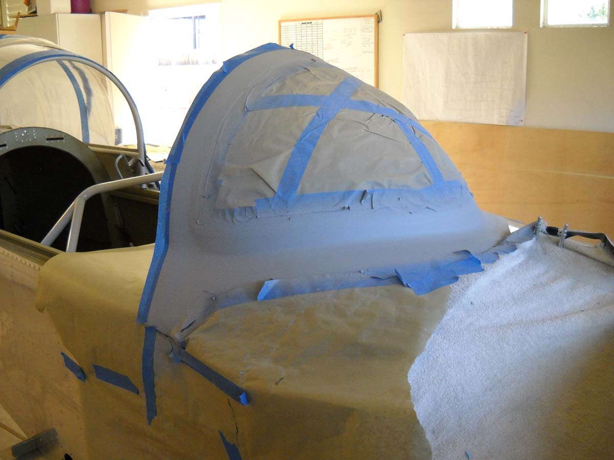
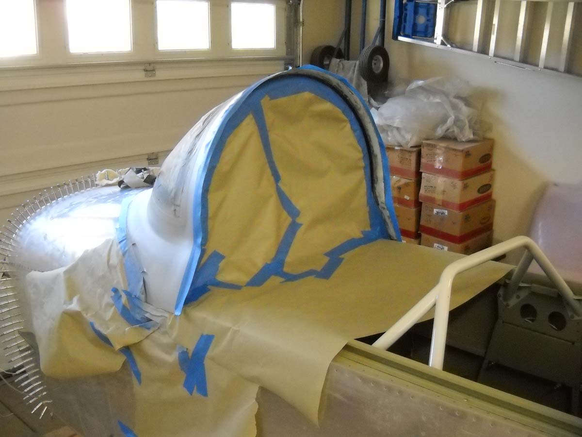
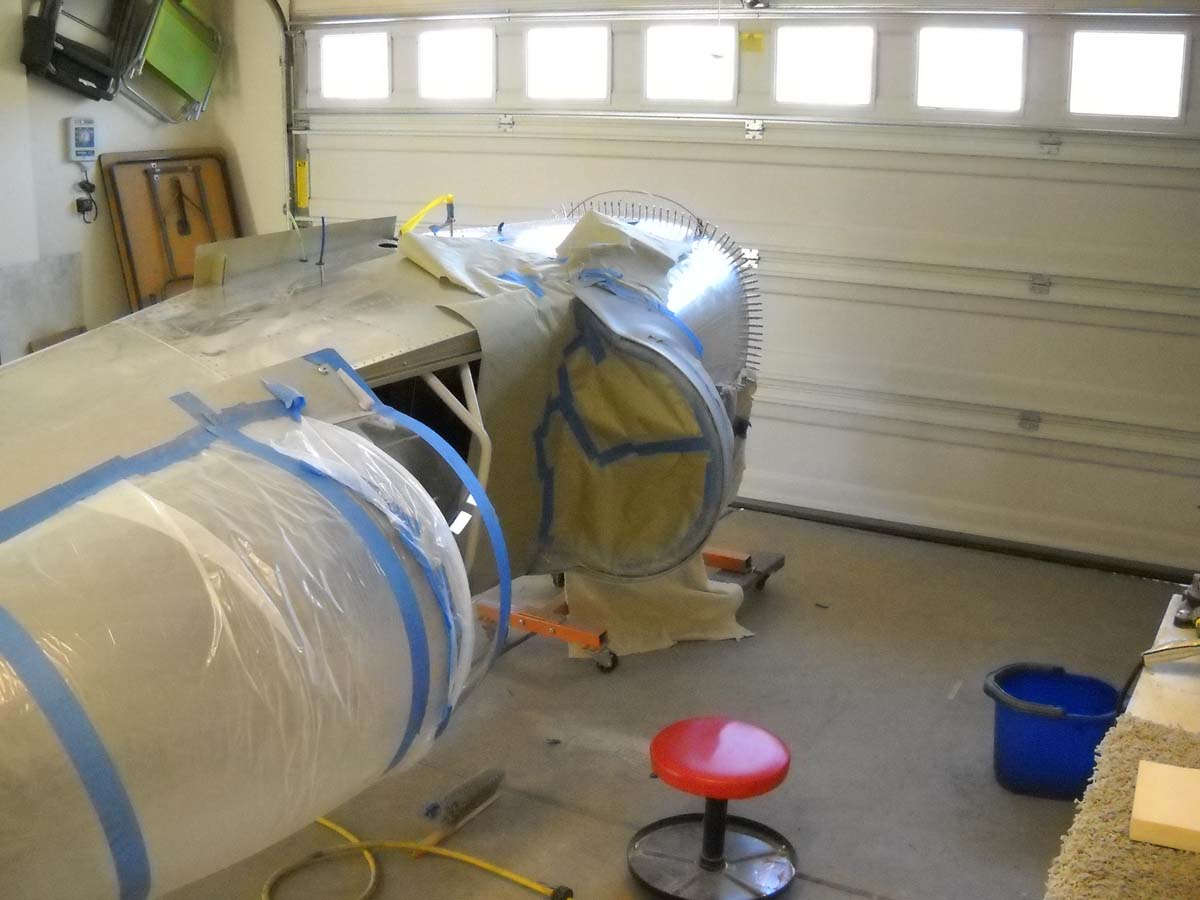
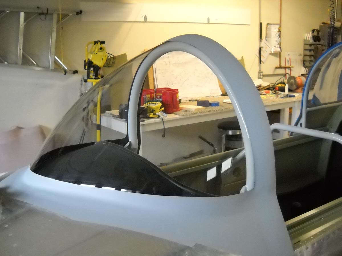
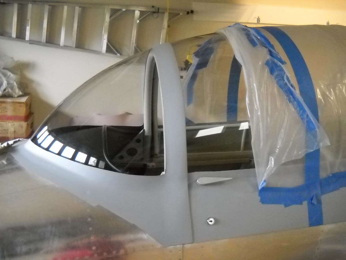
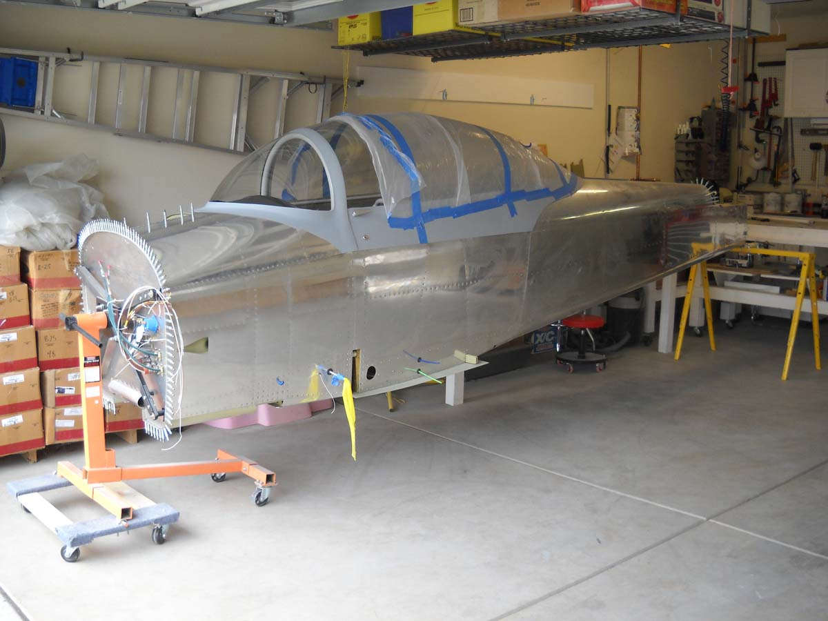
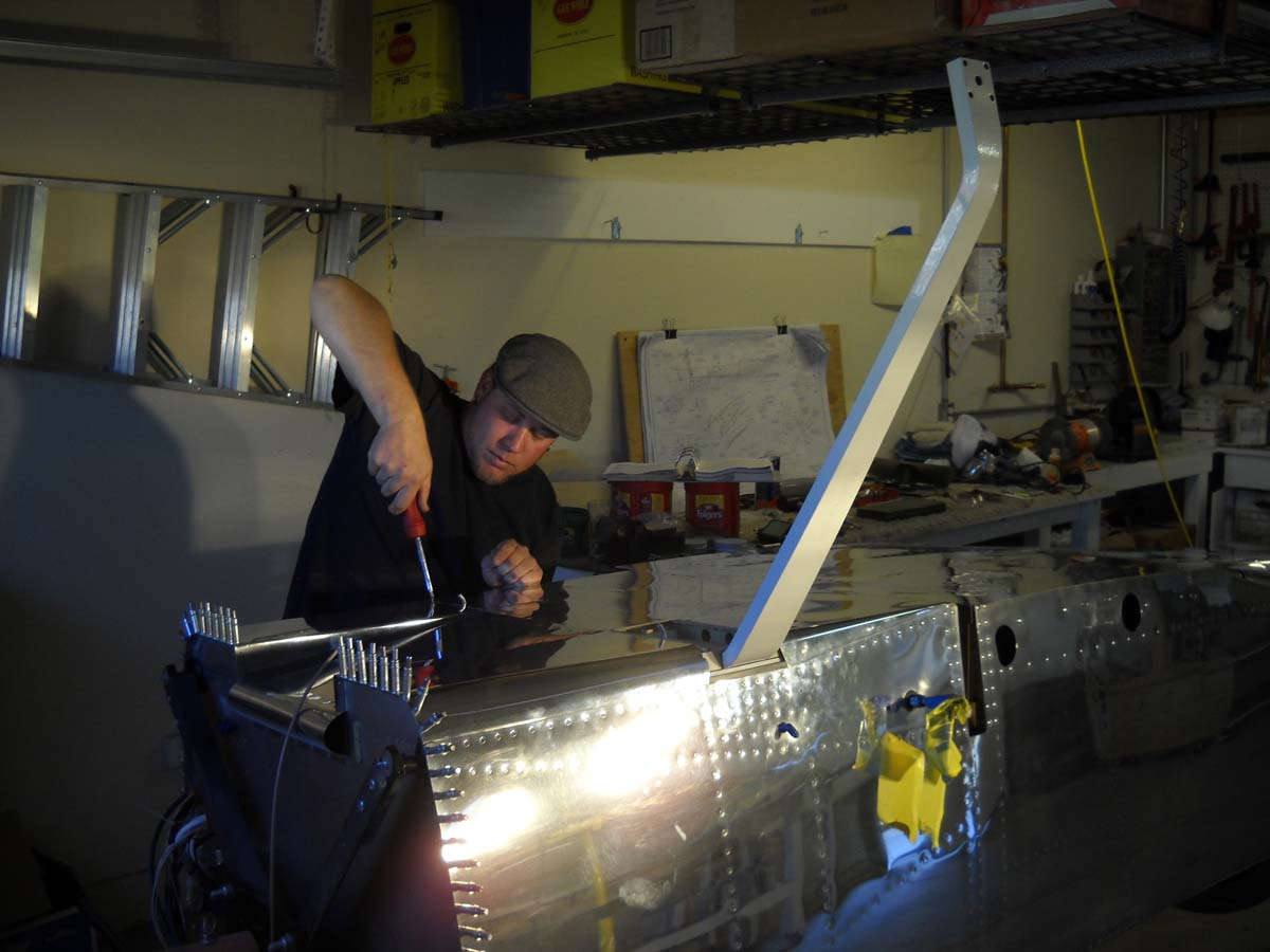
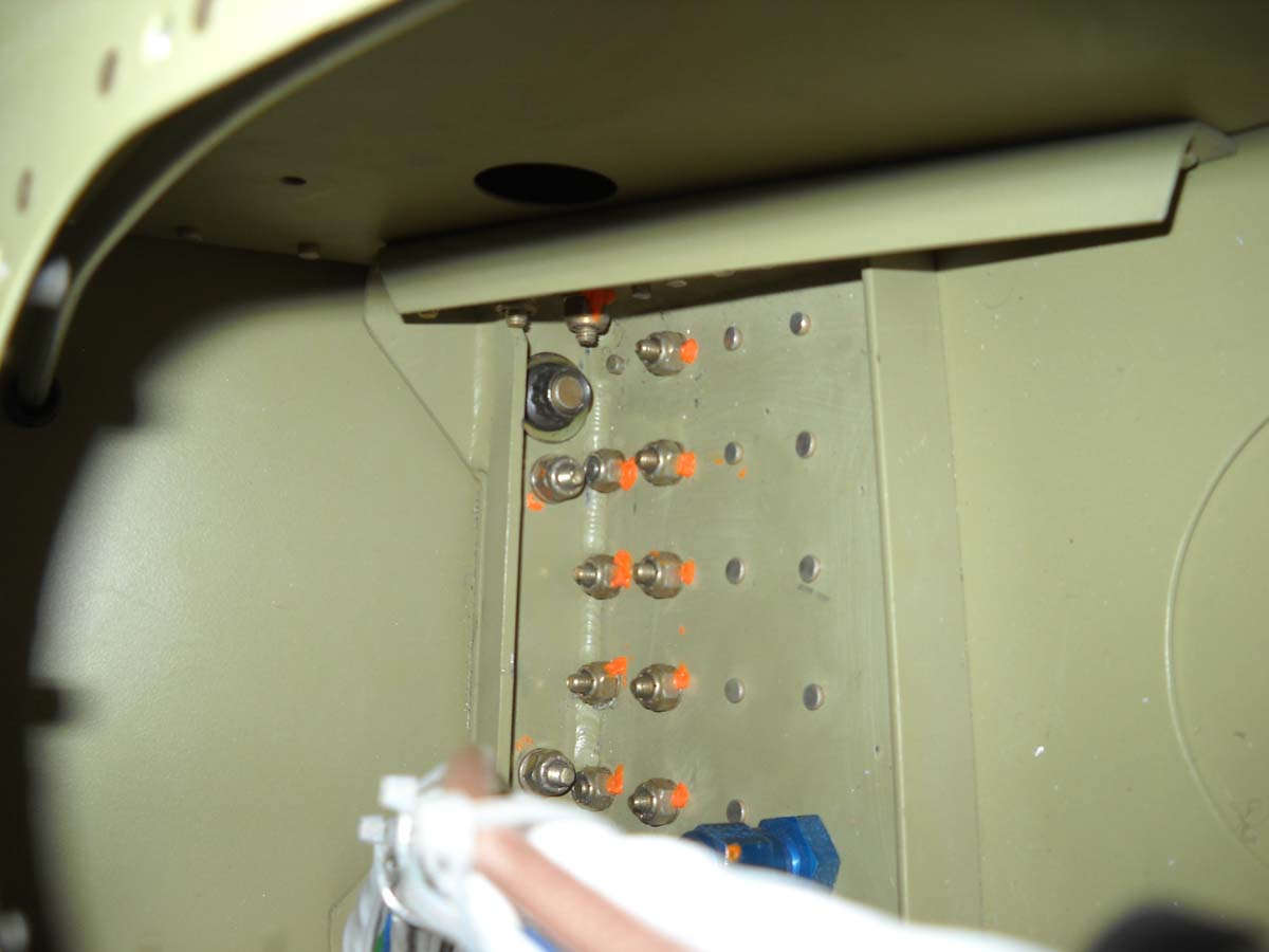
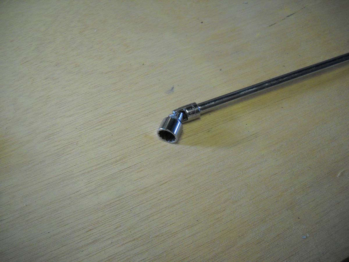
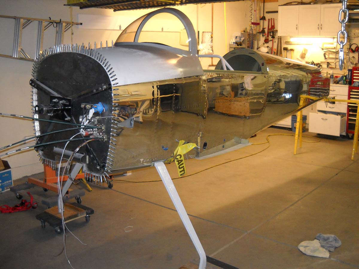
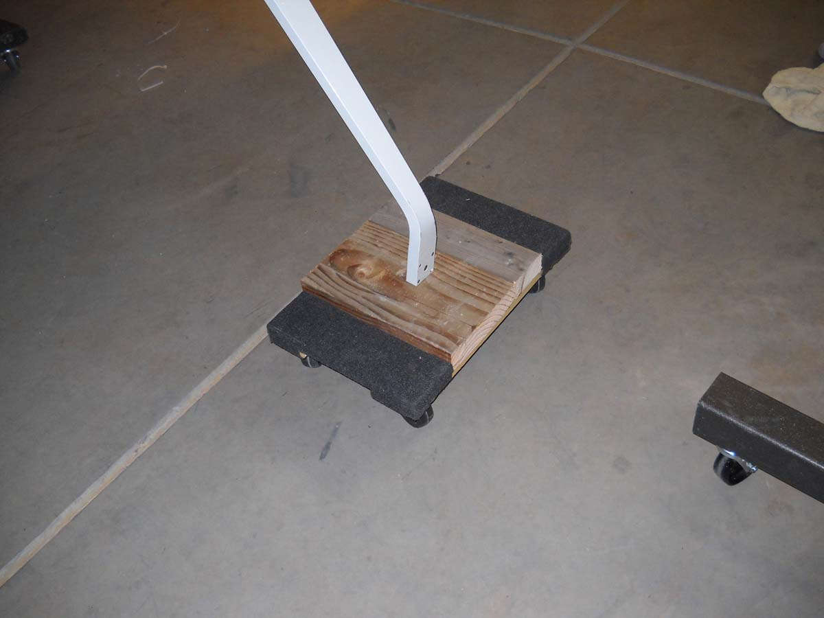
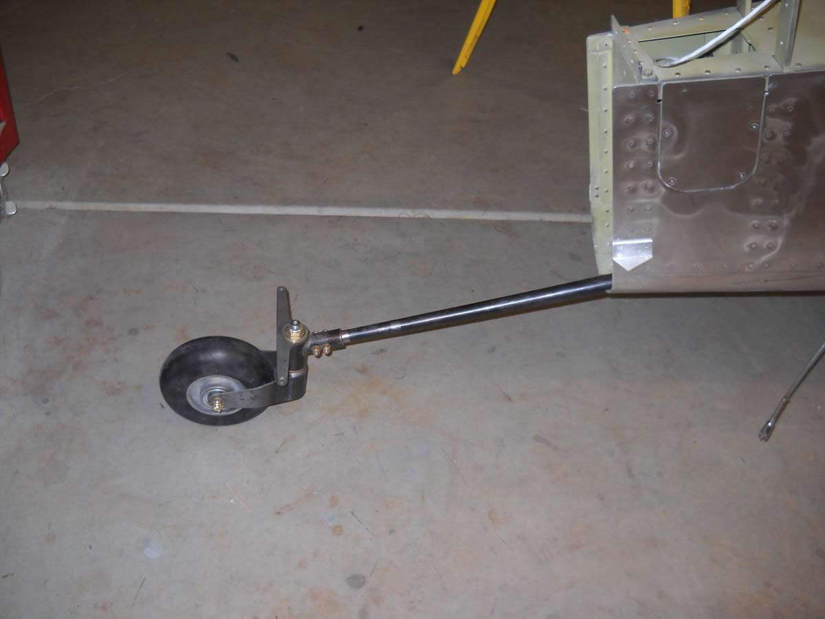
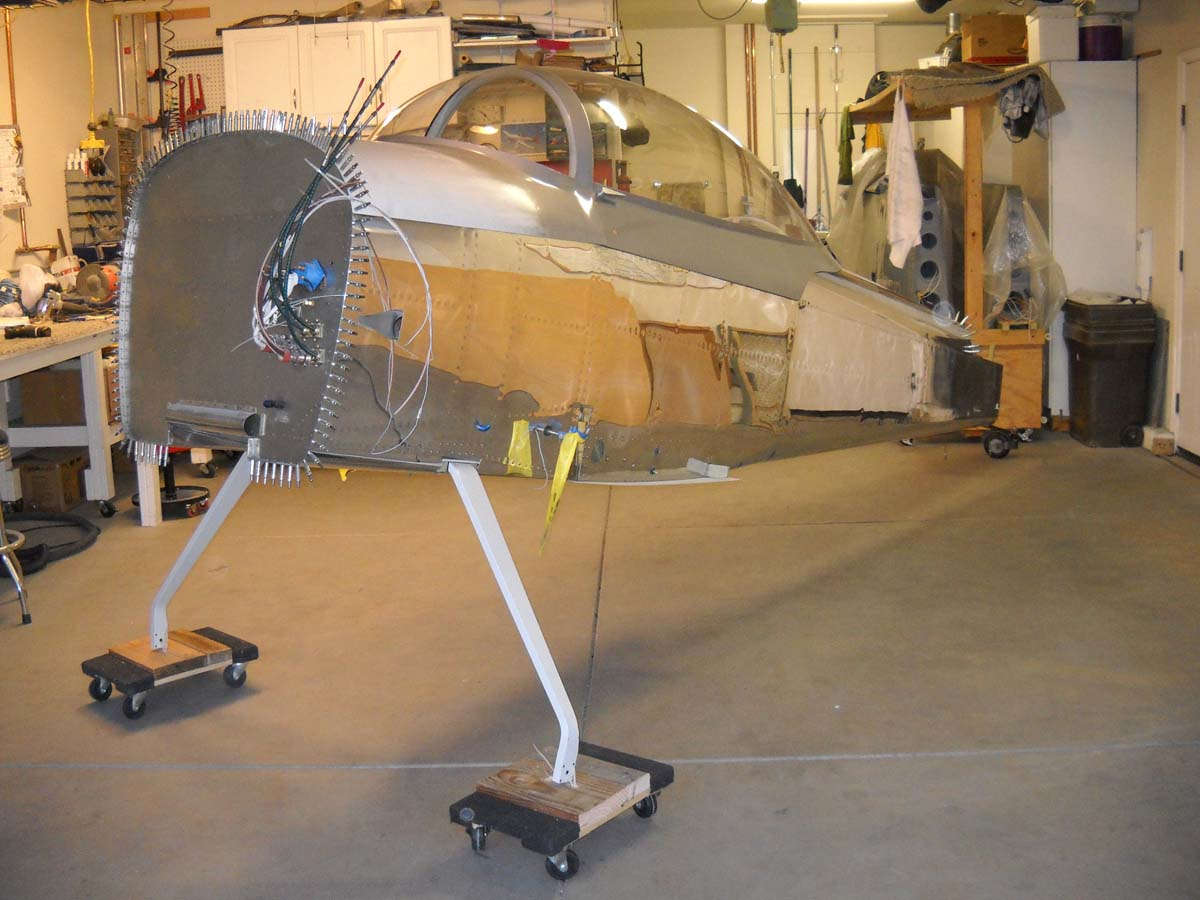
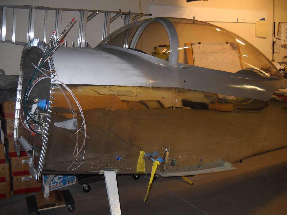
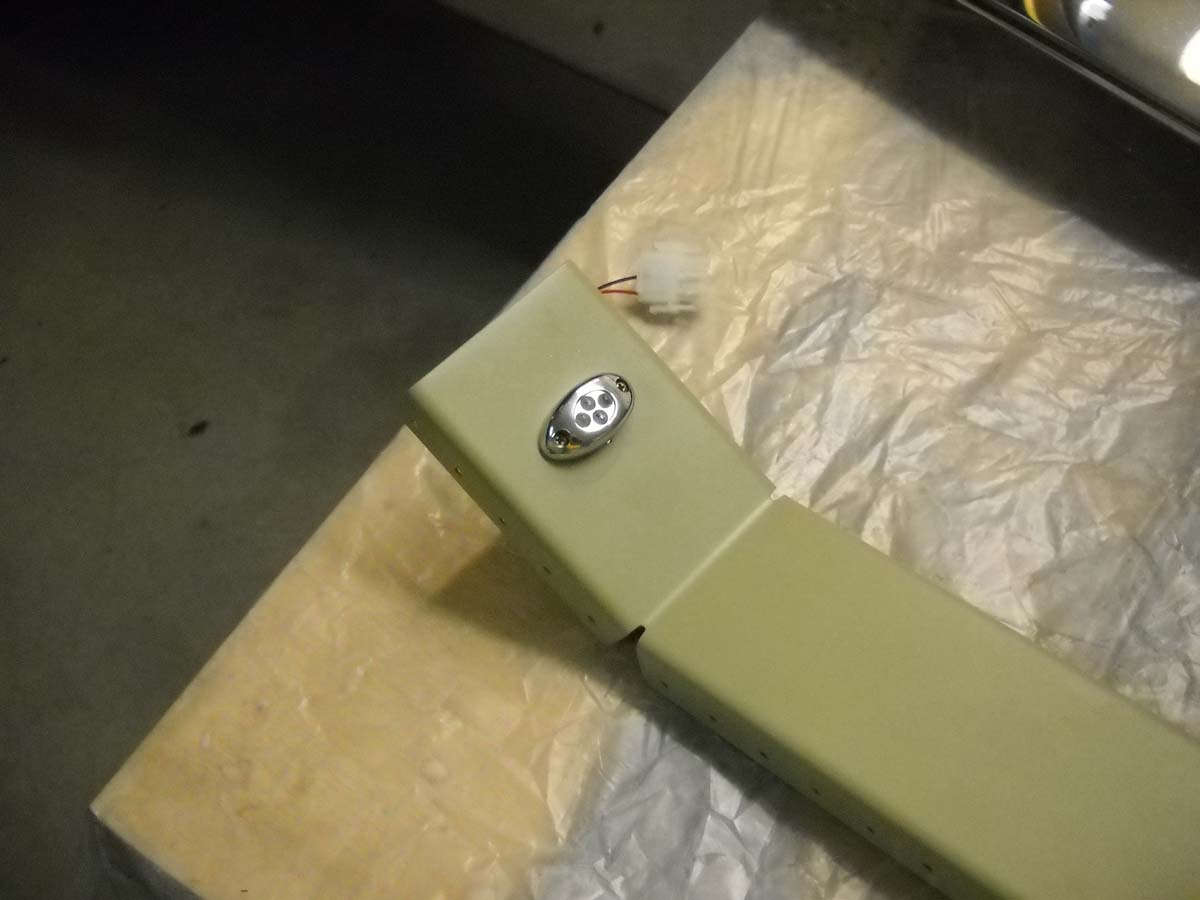
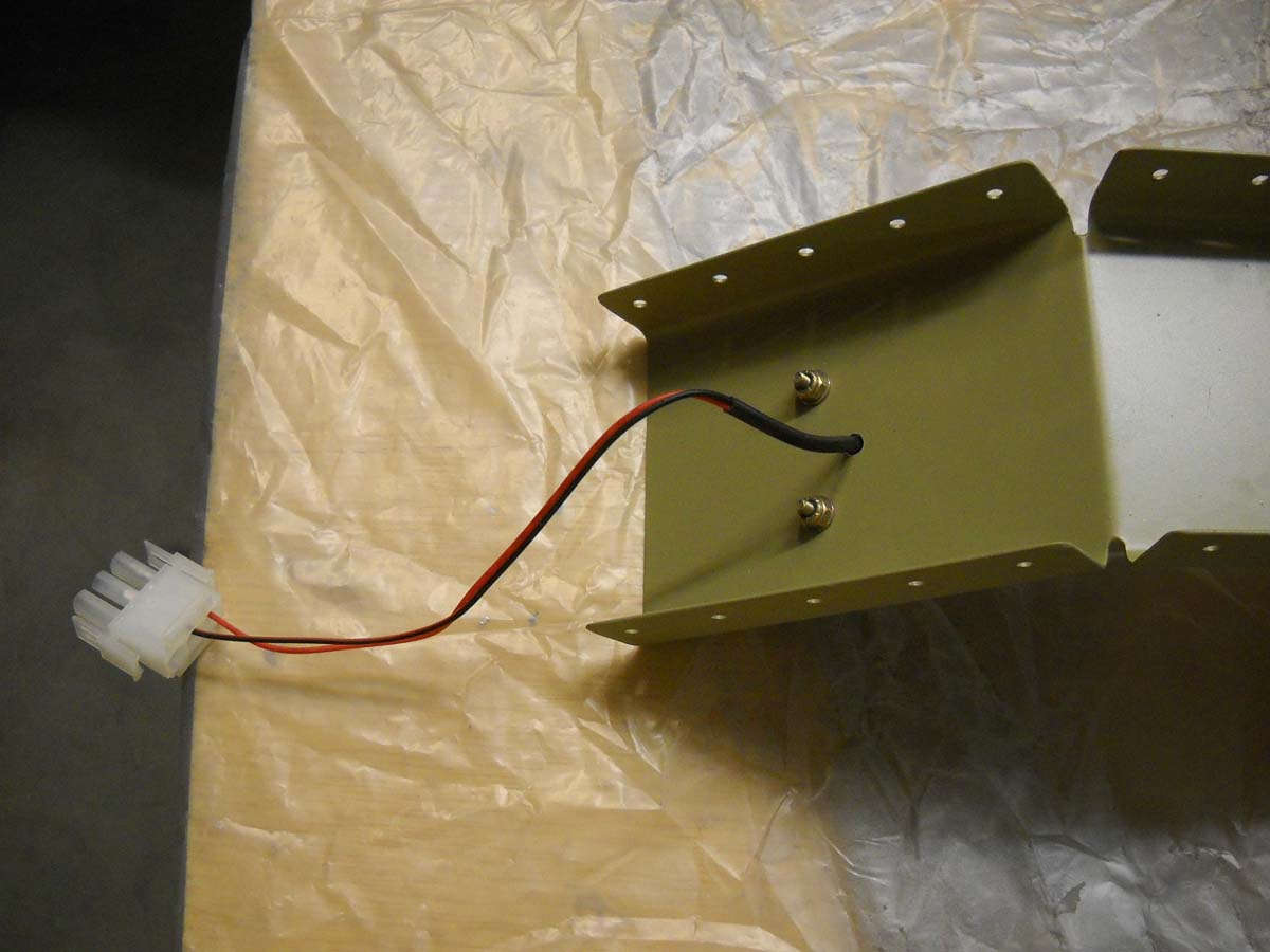


March 24, 2014


