
|
Building the Horizontal Stabilizer |
January 2009
Okay, so where do we begin? Well, the empennage is a very fancy French way of saying "tail section" and it includes the horizontal stabilizer, vertical stabilizer, and the elevator and rudder control surfaces that attach, respectively, to them. Those building an RV-8 usually start with the empennage and, if you follow the instructions, you start with the horizontal stabilizer, which is exactly what I did.
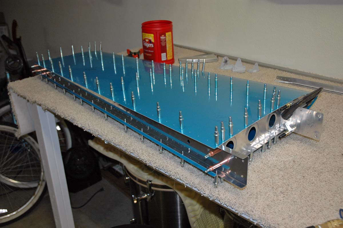
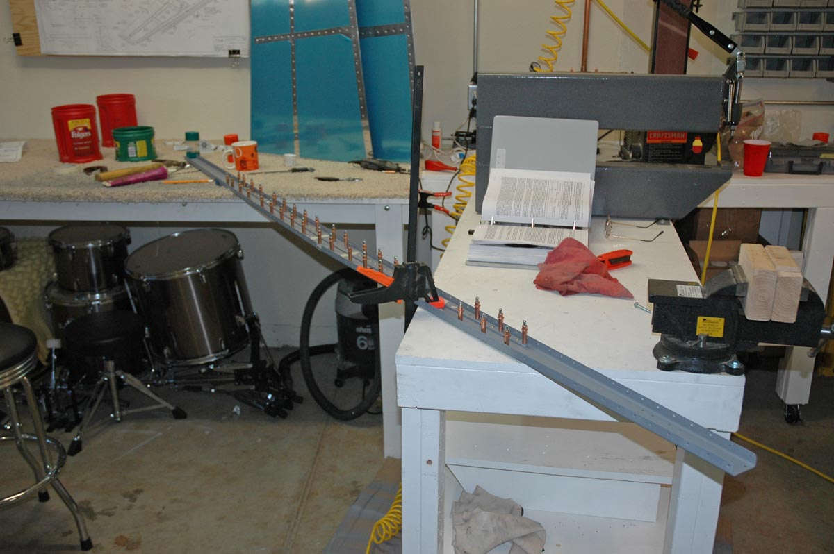
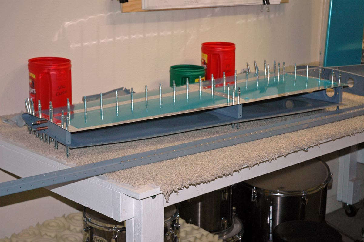
The RV-8 horizontal has two spars and each side, that is left and right assemblies, has three ribs, one at each end and one in the middle. It is a fairly simple structure that is a good learning spot, which is why it comes first. Fortunately, there are tons of resources to help you get it right, ones to pore over to figure out what this airplane building thing is all about. So, one cold (cold in Lincoln, California, is like 45 degrees, brrrrr...) January Saturday morning, I looked at the pile of parts and picked out, as per the instructions, the pieces needed to start the rear and front spars. The rear spar is assembled using a couple of milled pieces about five feet long that are riveted to a pair of stamped aluminum alloy pieces that, right and left, form the entire spar structure. So here is the basic assembly lying on my workbench:
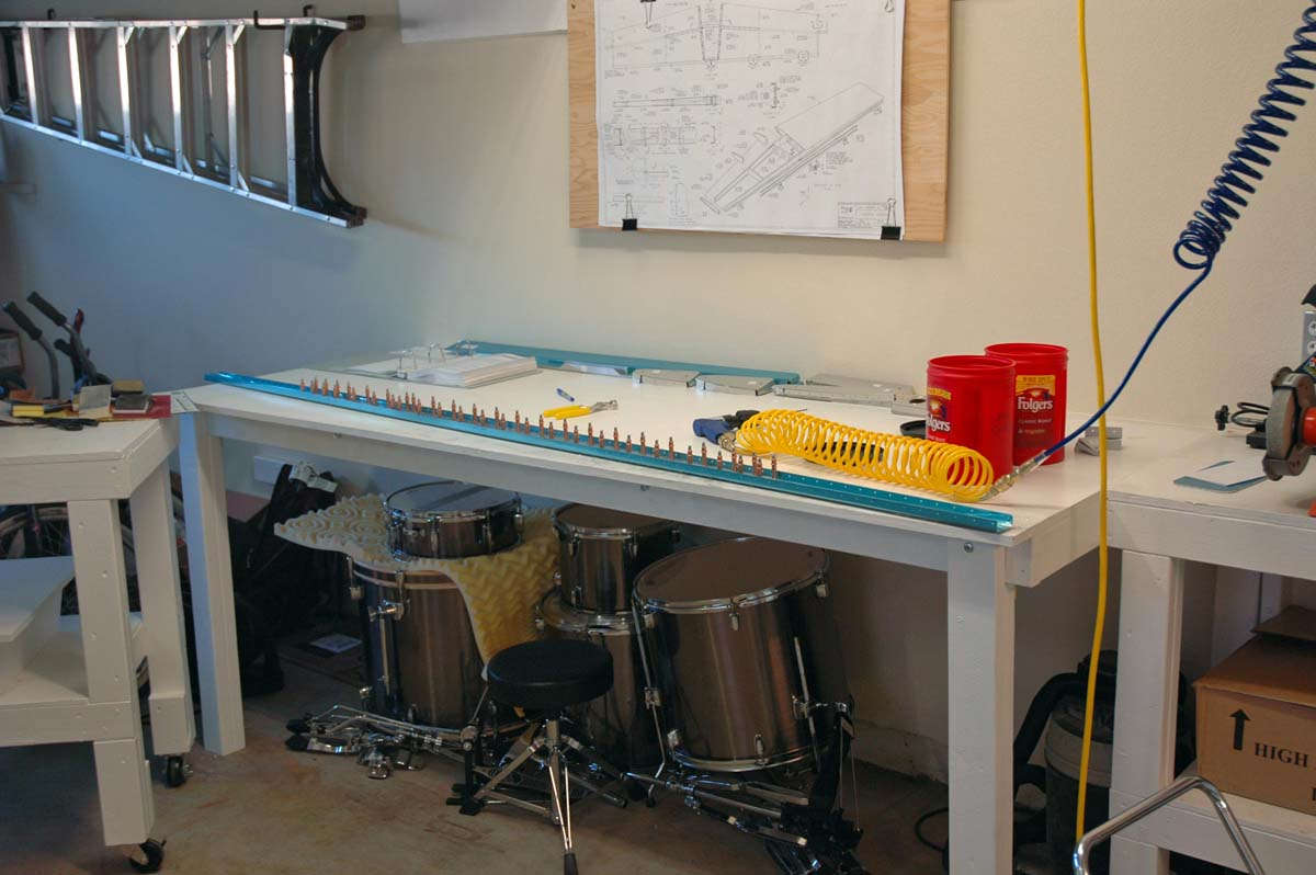
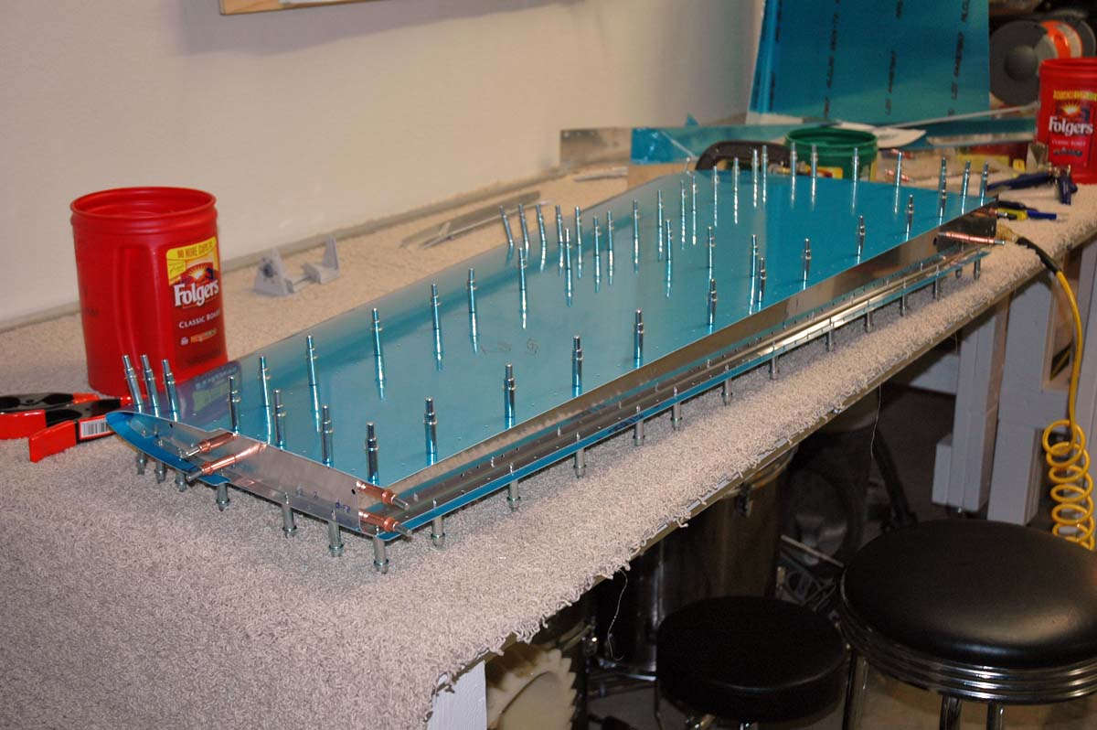
And another closer view:
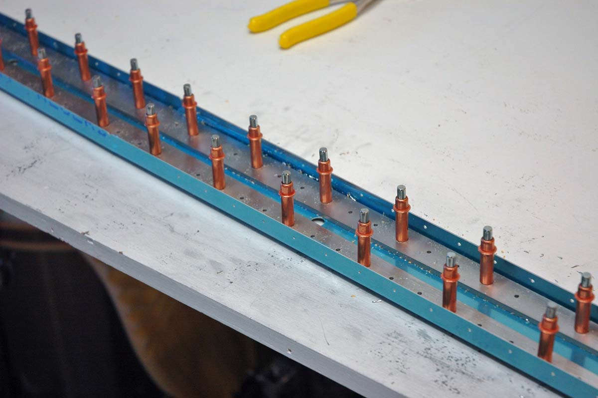
So, these milled parts have to be trimmed down for fitting and final drilled. Once the rear spar is trial fitted together it is set aside and work begins on the front spar. It is a bit more complicated as there are two milled parts that need to be prepped and actually bent to form a six degree angle to effect a swept front spar. This is slow going but enjoyable to just take a bit of time to figure out how to do it. It suits me.
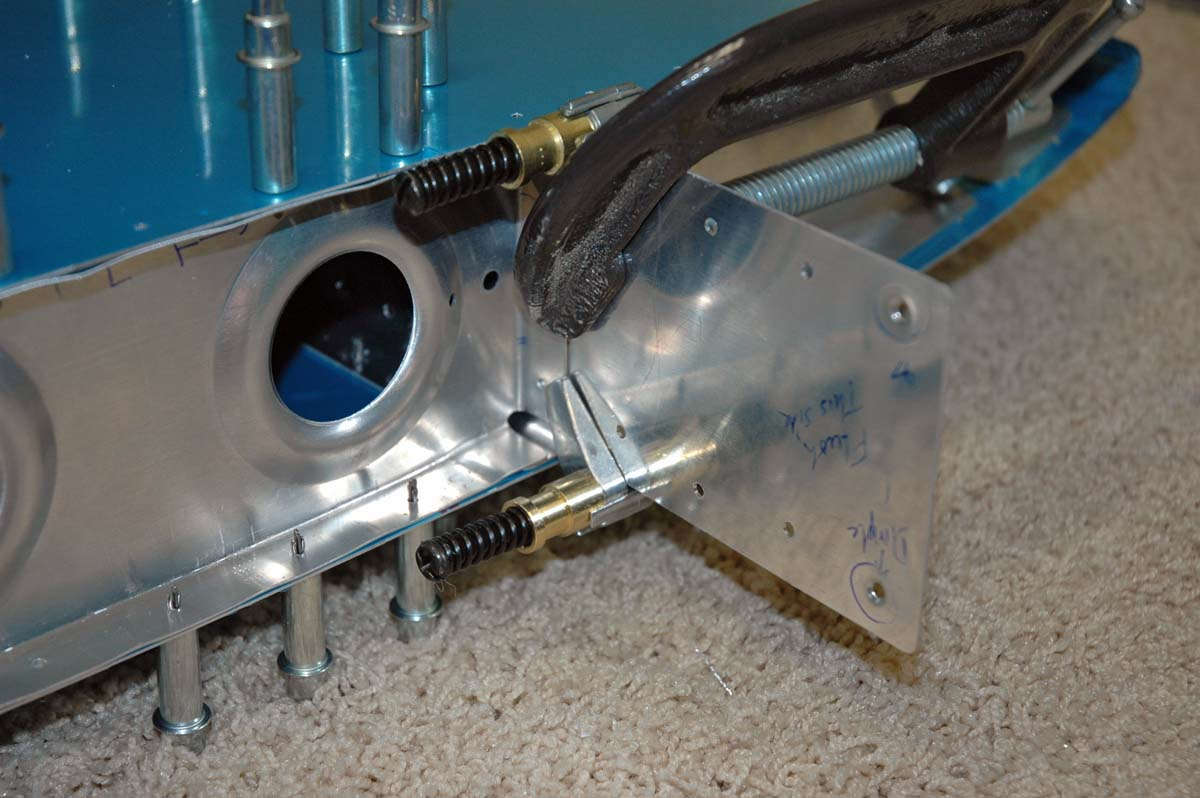
Here you can see the two milled parts clecoed to the left and right formed aluminum parts. The blue plastic protective film is pulled back to allow access but still protect the part of the formed aluminum I'm not yet working on.
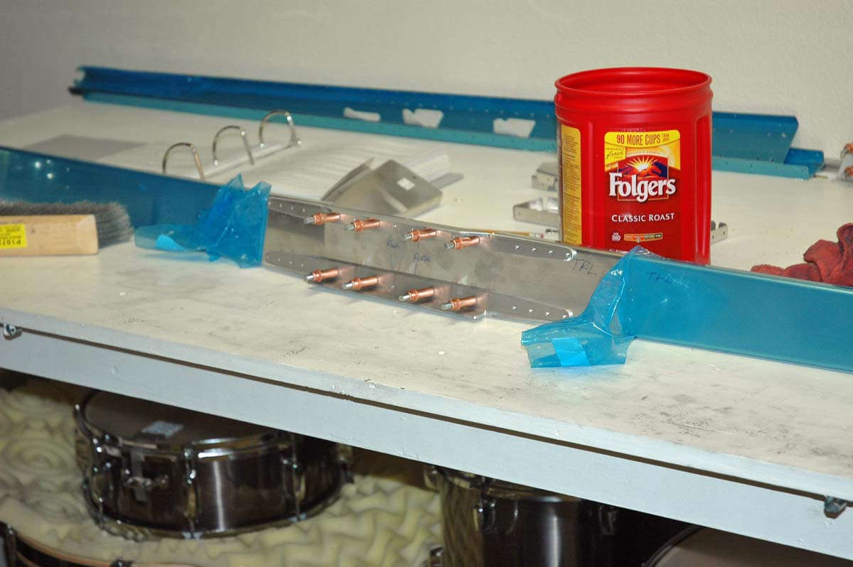
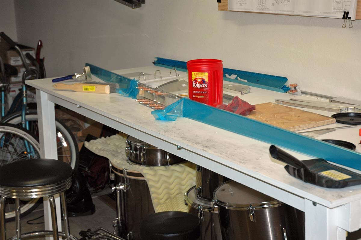
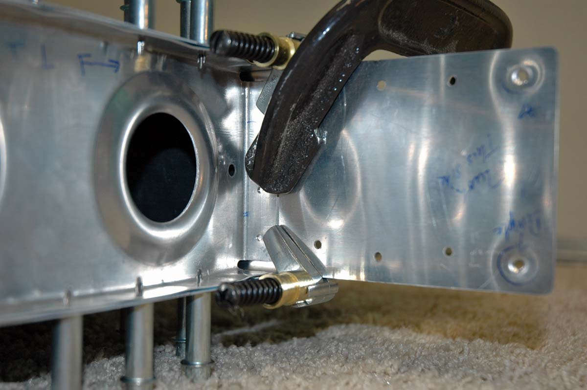
Here is another view but you really can't see the six degree sweep very well from this view. Trust me.
February 15, 2009
Well, slogging along here, flying for my job quite a bit. Just working on this assembly in between taking care of other things. There is a fair amount of work with each of the rib sections getting them trial fitted between the front and aft spar assemblies. Each rib is actually two parts...the rib section between the spars and the section forward of the forward spar that support the leading edge. All except the rib at the tip; it attaches the forward and aft spars and a fiberglass tip eventually is added. Anyways, after the tip and middle ribs are clecoed to the spars, the one-piece aluminum skin is fitted over the framework assembly, in this case the left side of the horizontal stabilizer. The idea here is to trial fit so the match drilling and final drilling of the skin can be done, as well as fit the inner rib into the assembly. Here is the skin fitted:
And from the other end. Starting to look like an airplane part.
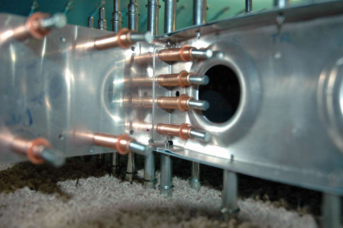
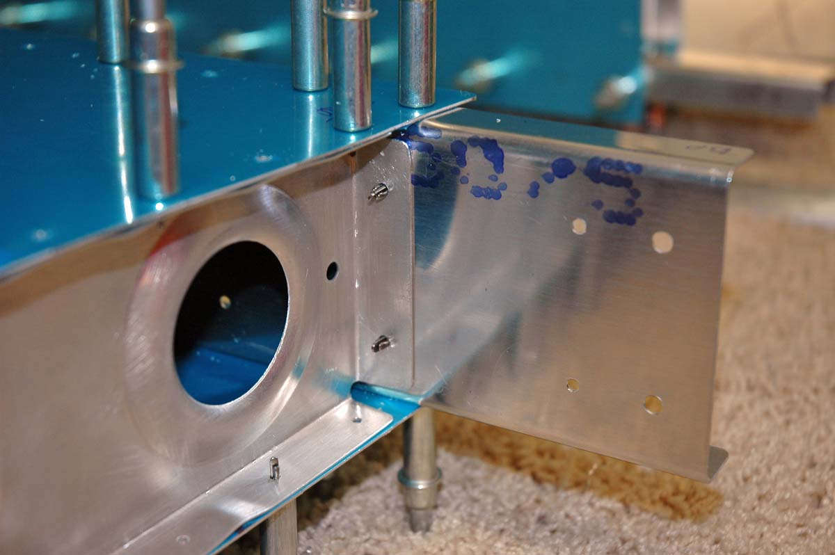
Okay, there is much care taken to insert the inner ribs into the assembly because the forward flange of the rib part that fits between the forward and aft spars will have four rivets inserted to hold the parts together, and the top and bottom of the four rivets have to go through three parts: the forward flange of one rib part, the formed aluminum spar part, and the thick milled aluminum structural part. The two middle rivets also have to go through three parts: the forward flange, the spar web, and the aft flange of the leading edge rib. Four rivets; not alot of room. Sounds hard, but the main idea is to make sure that each rivet has the proper edge distance so it can handle the design load stress. Lots of guys have had problems here by making the holes too close to the edge of the parts, so I measured like ten times and kept changing it around until it made sense. Overthought the whole thing. Final result worked for me, though, at least on the left side:
And a closer view of the forward flange of the rib section where it fits into the spar assembly with pilot holes drilled where the bigger holes will go when I get brave enough.
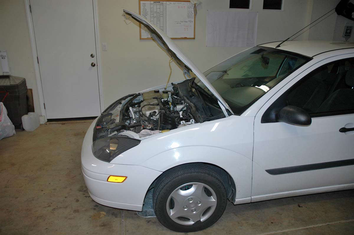
And then there is the challenge of wanting to put little airplane parts together when your Ford Focus has a leaking clutch master cylinder. Duty calls and the higher priority gets the wrenching. Unfortunately, the airplane has to take the last priority...kind of like family and job and household things and cars and emergencies and then maybe airplane construction. Bill Boeing had the same problem.
February 22, 2009
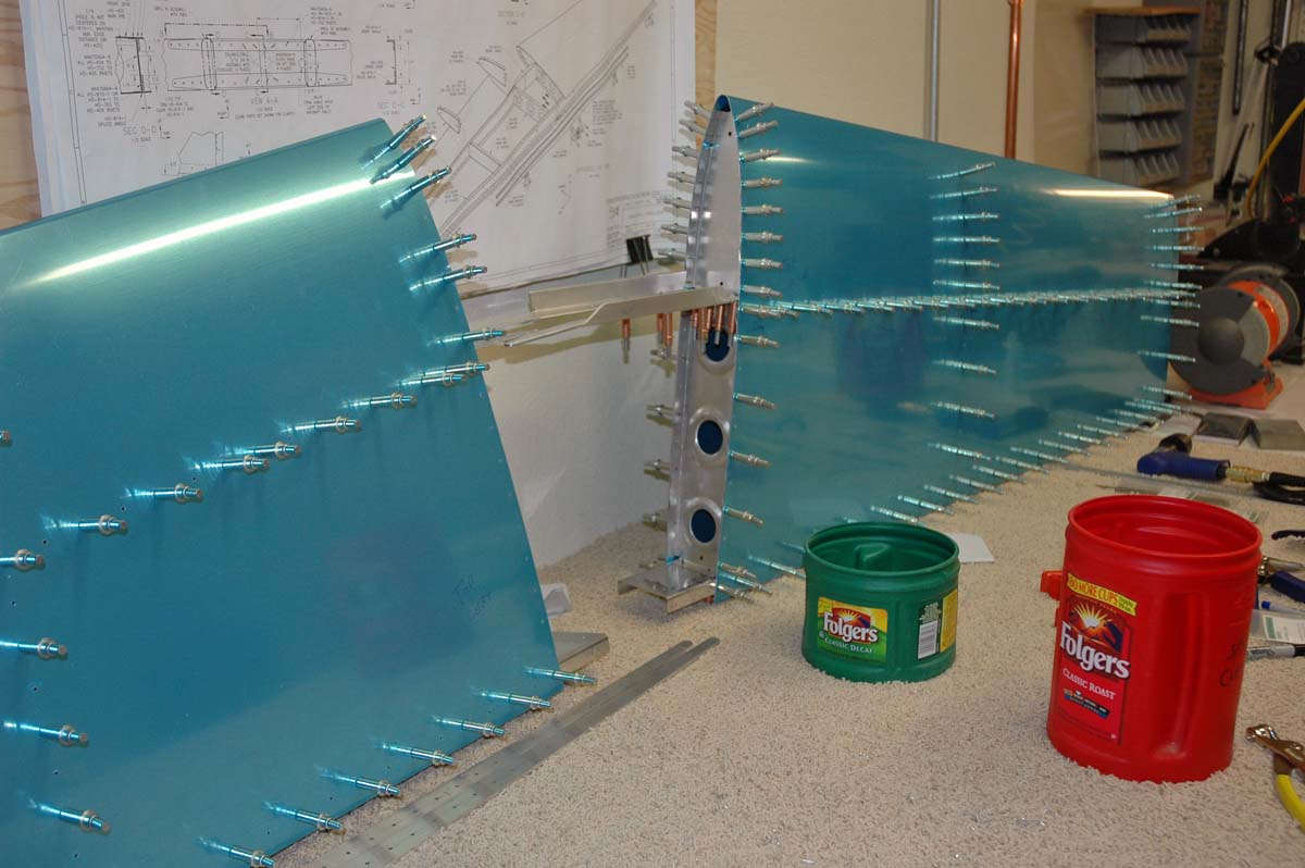
Okay, this week I continued to fit the parts together for final drilling and part preparation. Ended the week with the horizontal stabilizer in this conditon, basically complete and ready for disassembly.
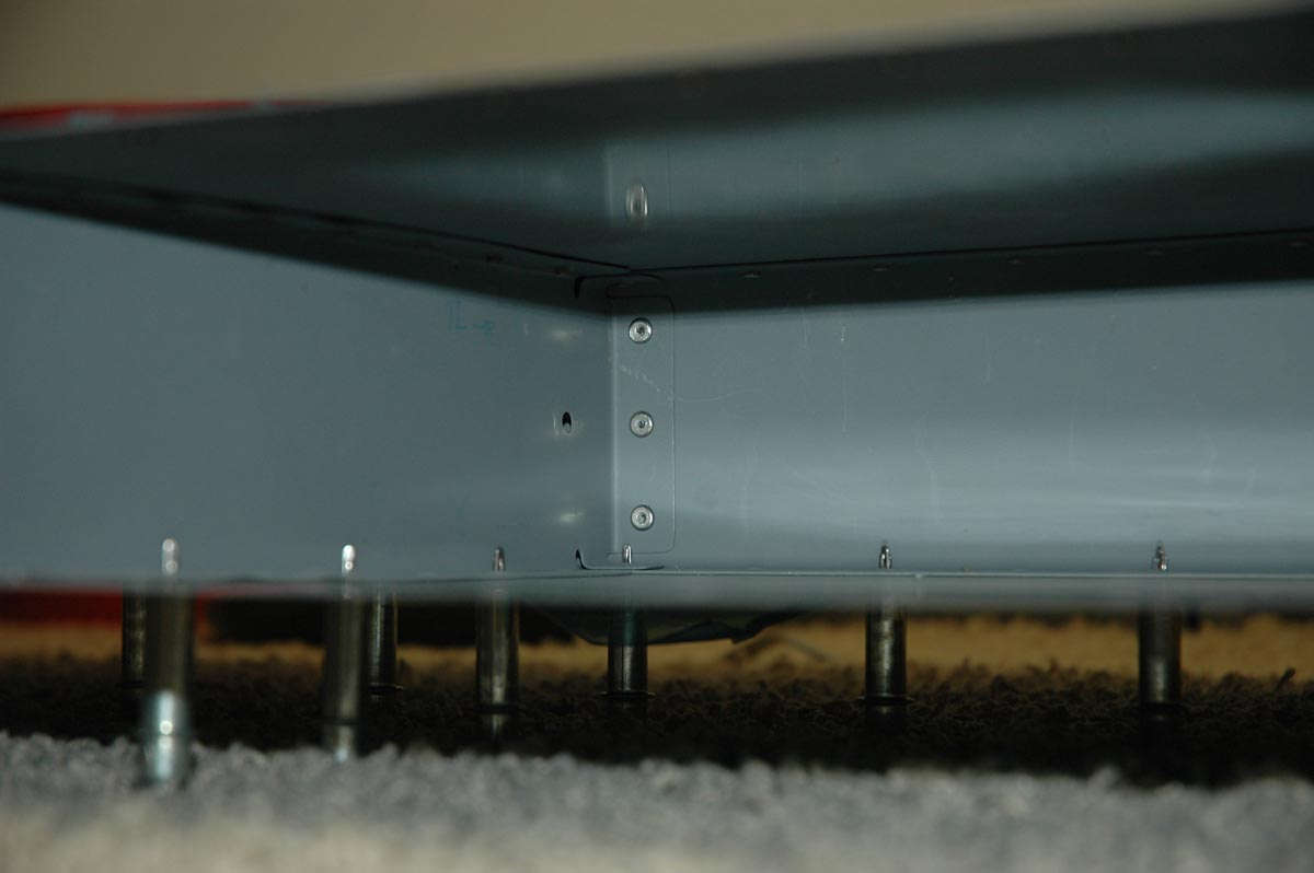
I did get brave and drilled the Mt. Everest of the Horizontal Stabilizer, that being the HS-405 forward flange to the forward spar. Turned out okay. This is the attach point HS-405 side (on the right horizontal):
And the other side:
And the aft side of the HS-405 where it attaches to the aft spar:
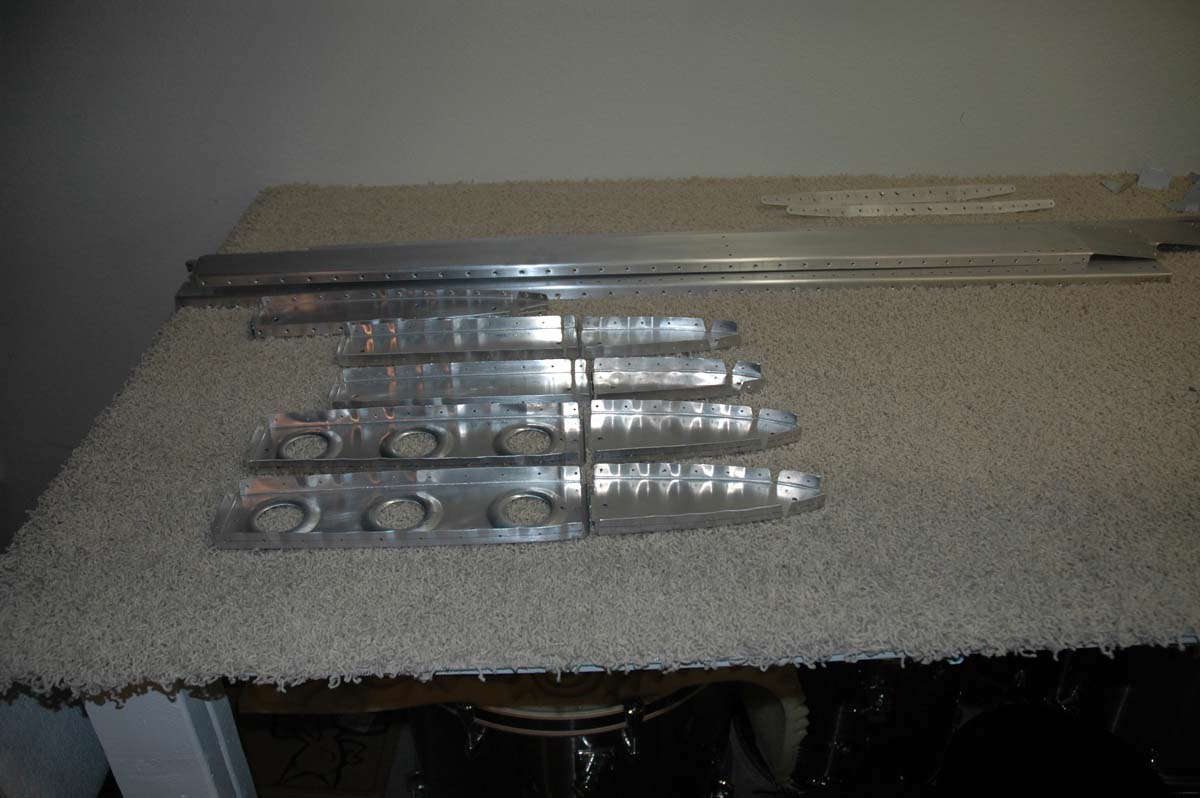
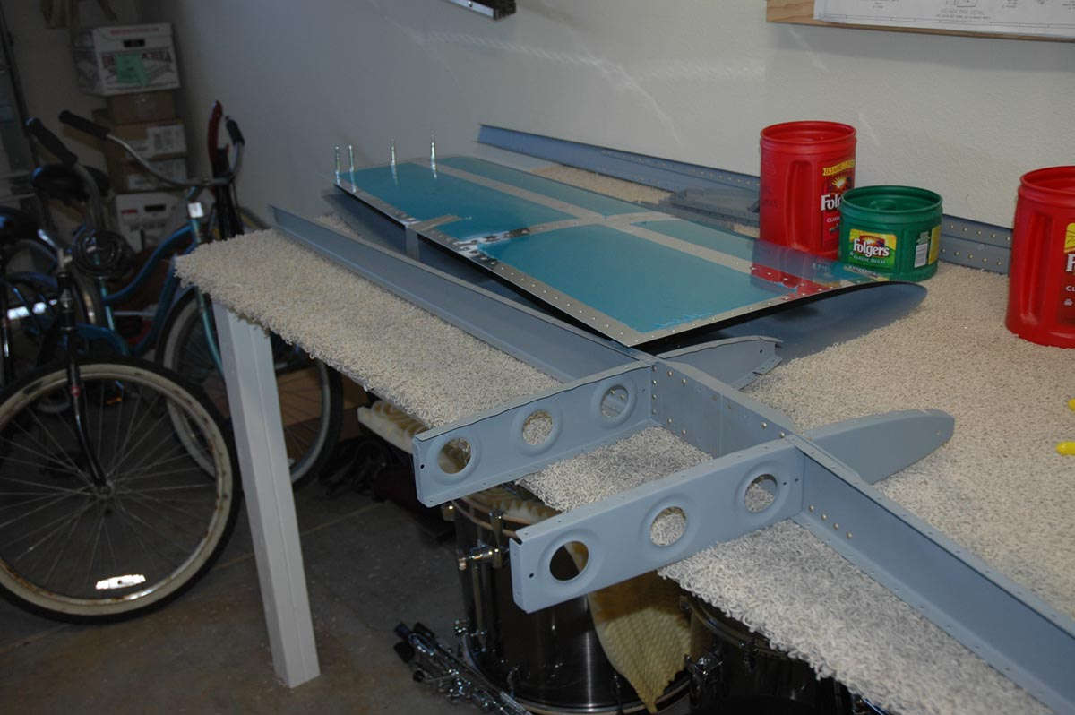
And then the whole thing comes apart and the various parts are prepped for actual assembly. Here are all the ribs and spar parts laid out because they are pretty. A bit of laborious preparation is now forthcoming. Stand by for deburring, and dimpling, and doing things to the sharp edges.
March 1, 2009
Spent a few sessions this past week working on parts preparations. This included deburring each of the holes, a process that uses a little tool to remove tiny burrs, or raised ridges of metal, that result from drilling a hole. The burrs can cause stress points and possible cracks later, plus prevent the rivets from sitting down in the holes all the way.
I also dimpled all the surface skin holes and the mating surfaces on the understructure. The dimpling allows the use of flush rivets, so the final skin will be smooth with much less aerodynamic drag than if raised head rivets were used. Of course, one needs to be careful when using the pneumatic squeezer to dimple holes as if one get a bit too quick the bugger will add a dimpled hole where one doesn't want one. One can get really disgusted with one's self if that happens. Especially if it happens twice.
One will need to add an extra flush rivet to fill the extra hole. One has also decided that if anyone asks, this extra rivet is to mount the optional digital elevator thruster dampner on the inner skin. They'll never know.
Got my son Adam out into the garage for a second set of hands to manhandle the skins while dimpling. He helped me on the right half of the horizontal stabilizer, the one that doesn't have the extra holes and the one that ended up with much fewer skin scratches.
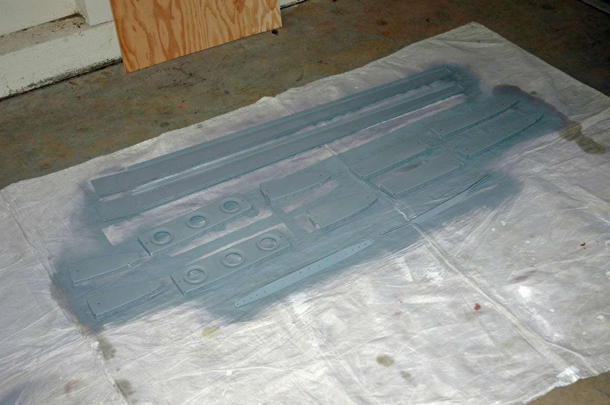
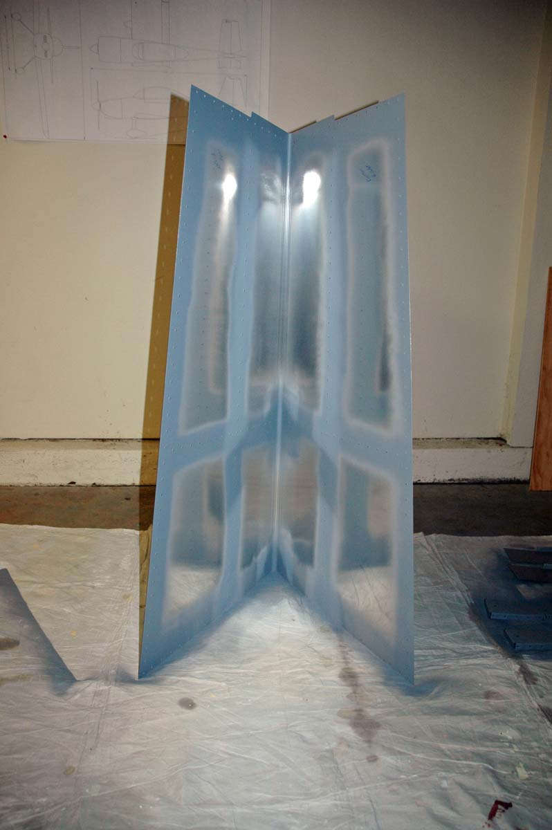
So, once deburred and dimpled, it's off to the paintshop which, it turns out, is about ten feet from the assembly line and is on the garage floor. I read and reread all about the "primer wars" and what to put on the inside structure to keep it corrosion free. I decided less is more, and will use a rattle can self-etching Napa 7220 primer. I did a bit too much prep work on the ribs so the alclad aluminum surface might be compromised. Prime all the components, as seen here, and learn to be a bit less busy on the vertical stabilizer and other parts.
As an editorial comment, I don't know nearly as much about this as the smart primer people, but for how these airplanes and, particularly, this airplane, will be flown, I'd rather not get too carried away with surface preparation. It's not like this thing will be flying in, like, the year 2512.
I also sprayed a bit of primer on the interior skins where the ribs attach.
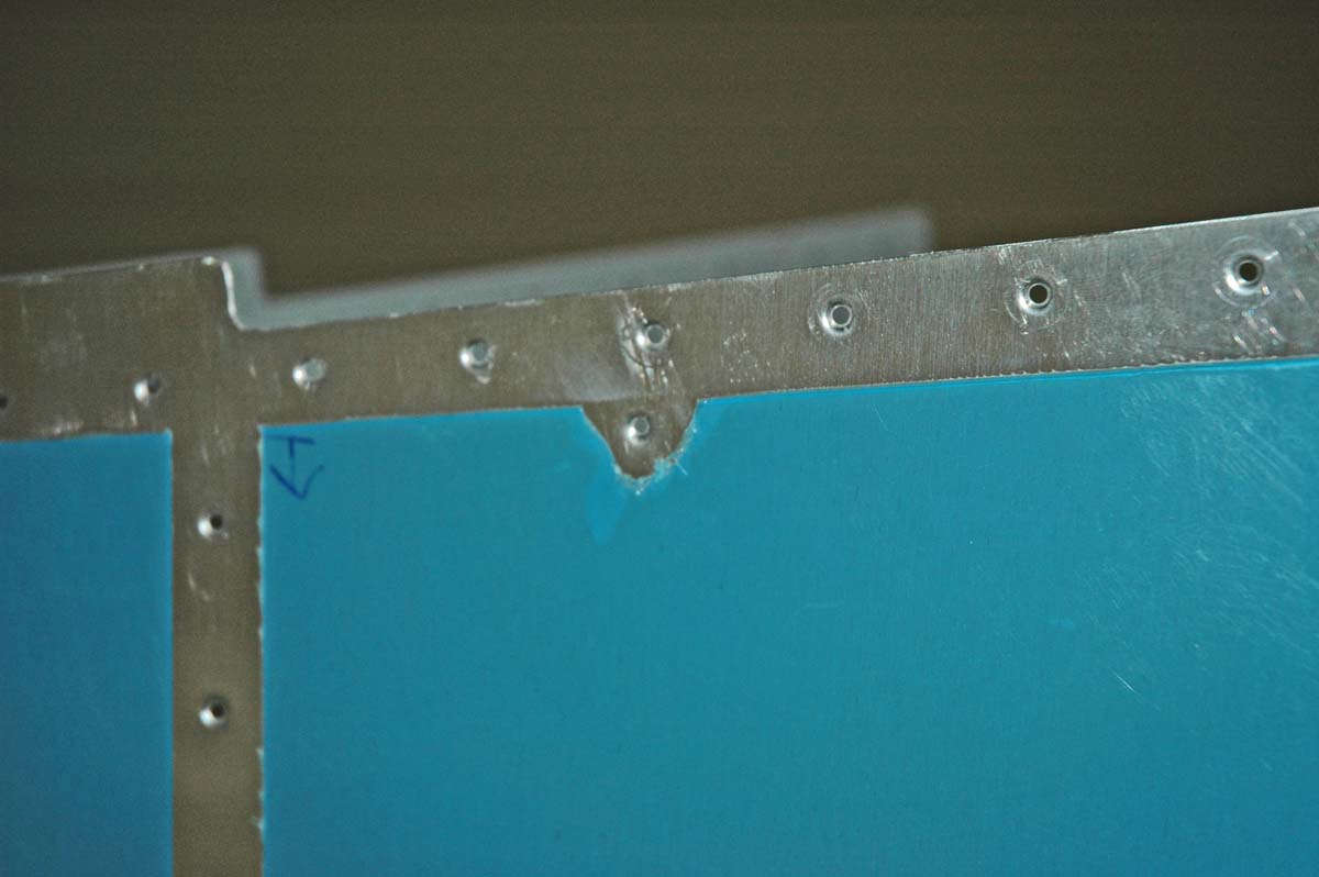
So here is one of the dimpled and prepped horizontal skins ready to go. I used a soldering gun to melt the plastic in such a way as to enable me to peel away the plastic film from where the rivets will go. It amazes me that some builders lay these rivet lines out with exactly straight lines with measured to the inch with rulers, a process that seems to take alot of time and effort. I have to admit nice straight lines of blue film looks pretty cool but the point for me is to protect most of the skin through the riveting process. After the horizontal stabilizer is done, all the blue film comes off, so I'm not too concerned in my lines aren't straight.
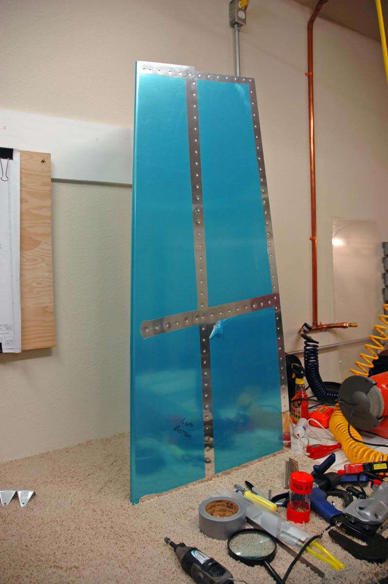
By the way, the corner of the blue film in the one section is peeled back just to make sure my soldering technique doesn't scratch the skin. It mostly doesn't, but I need to be careful. So, after all is said and done, we are ready to rivet the horizontal stabilizer together. Next weekend, I become a man.
March 16, 2009
Okay, so two weeks go by like...poof....
Got to spend one weekend fixing a computer...that pesky blue screen of death syndrome. But I did get a few hours on the old RV-8.....up to riveting some serious parts together. Not a great job, but the learning curve is there and I'm climbing my way up it.
I did rivet the aft spar together...didn't take too long and only had a few "quality control" issues (as in drill the rivet out).
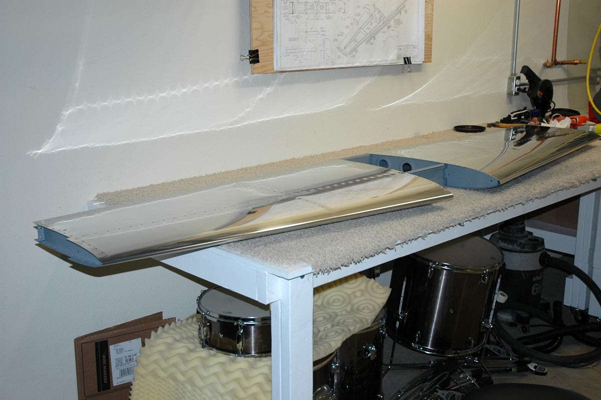
So, here is what I started with....the spar assembly is ready to be inserted into the right side of the horizontal stabilizer. I've already flush riveted the nose rib into the skin section, and then the spar assembly is slid into position.
Then that thing is clecoed together for riveting....
Here is one of my sons, this being Nathan, learning how to rivet. Where it takes two to tango, he was my partner for the day to get to some of the hard-to-reach-with-one-person rivets on that nose rib.
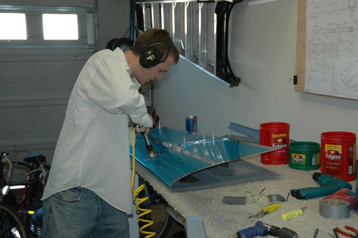
As is to be expected, the actual riveting doesn't take too long. Here is the right side assembly with all rivets in that have to be done with a rivet gun. The ones on the edges can be squeezed.
In the assembly process, that nose rib in the middle of the assembly is attached to the forward spar and the aft rib using pulled rivets. This is about the only way this can be assembled as there is no longer any access forward of the forward spar. So, it turned out okay, eh?
And, moving the camera eye to the right a bit, here is the aft side of the forward spar where it meets the interior rib...the one closest to the fuselage (someday).
So, the week to come, I hope to finish the horizontal stabilizer. Should come together okay, We shall see.
March 23, 2009
Worked off and on this past week on trying to finish up the horizontal stabilizer. It is just about there....just a few little bits of tid to complete.
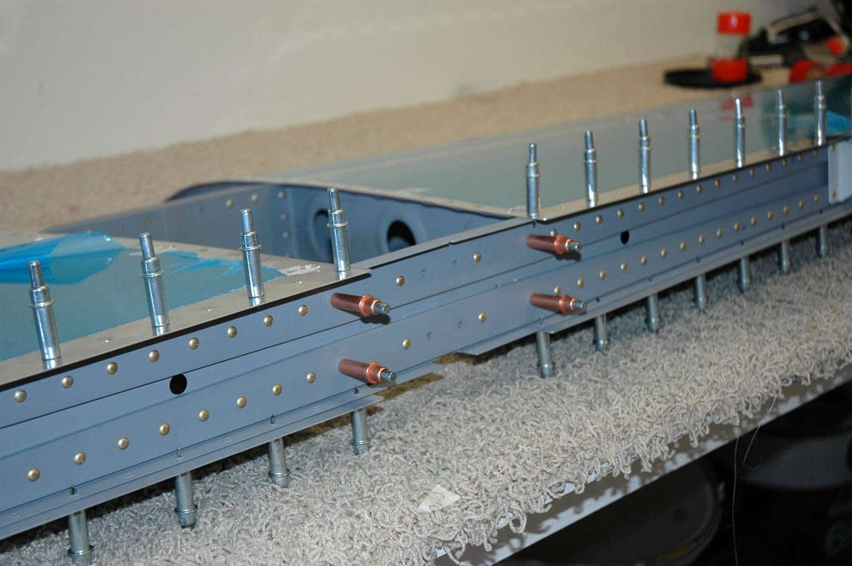
Here is the assembly with the interior rivets completed and with the aft spar fitted into postion.
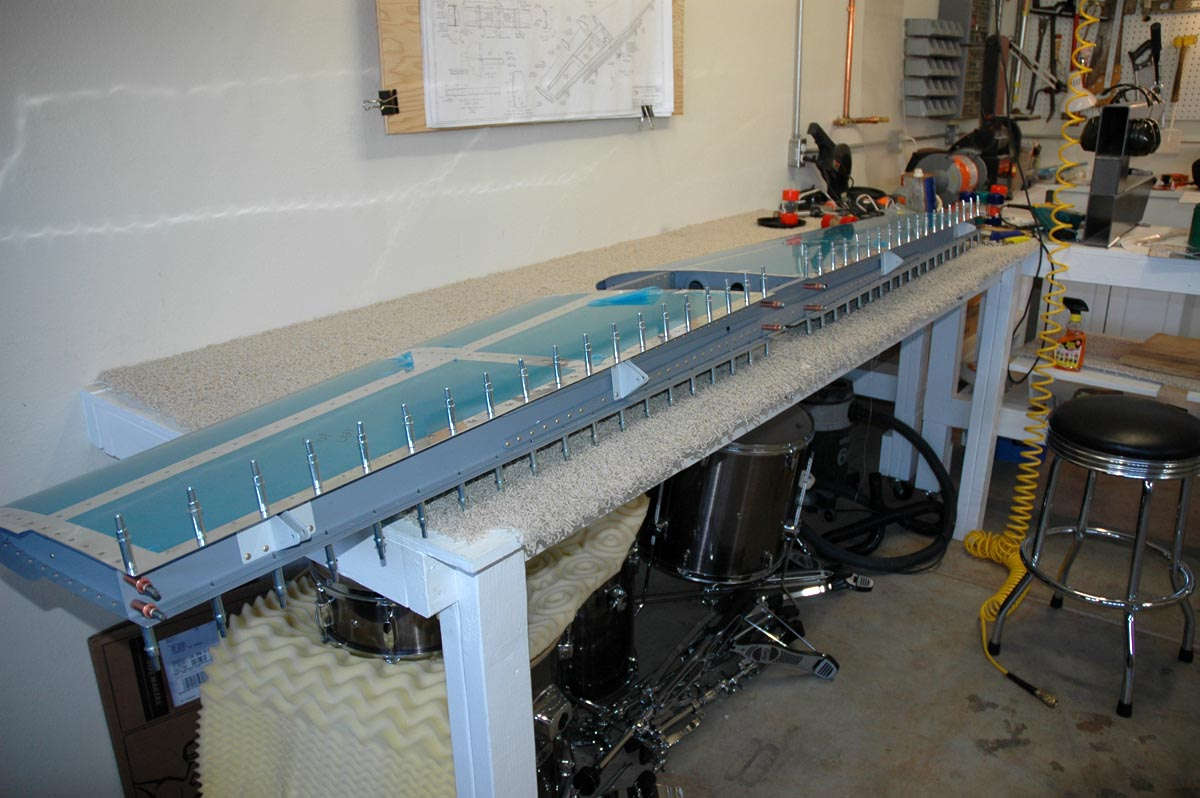
And another closer view. Every other hole is clecoed in preparation for starting the riveting. I had a bit of trouble trying to figure out how to use the pneumatic squeezer on these rivets...the part I wanted to be stable was the part that moved. Not as good control but I figured it out. Only had to drill a couple of out. I'm getting better at drilling them out. My technical assistance team (a bunch of excellent FAA mechanics that normally work on Learjets) gave me a few pointers...well, actually many pointers. And away we go....
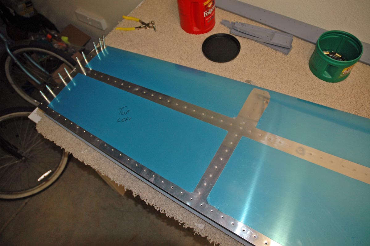
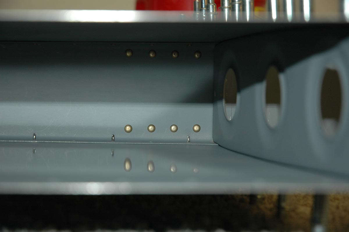
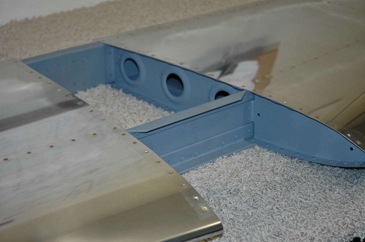
So tonight, Monday night, I finished riveting the rear spar into position and attaching the ribs to the spar. Ripped off the blue plastic protective film and here's the thing about done.
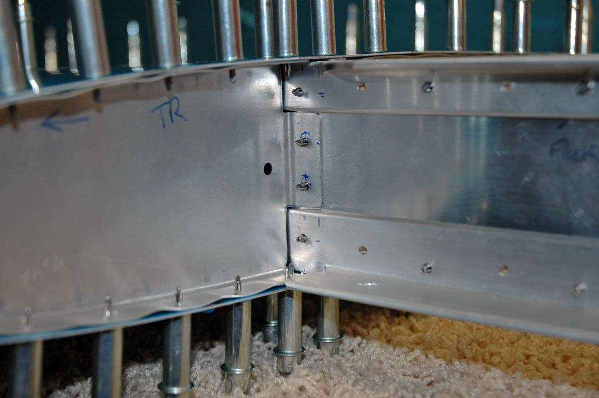
A closer look at where the two halves join...this will someday be the part that attaches to the aft fuselage. I need to do a bit of touch up priming and attach the center elevator hinge before I can say it is really done. The missing rivets on the interior edge are supposed to be there. A close reading of the plans tells me that an aerodynamic fairing will be attached at these holes during the final assembly.
Not 100% happy with my skill level on some of these little parts, but I guess that's part of the process. Next session I'll do the painting and finish it up, and then figure out a way to store this assembly for awhile. Then, on to the vertical stabilizer. Done with "HS" parts...now to "VS" parts.