Preparing the Wing Spars
February 1, 2010
Well, the wings were delivered safely by a FedEx truck on January 20: two big wooden boxes showed up as expected. One box is 16 feet by about 1 foot by 1 foot. The other box is 8 feet by about three feet by about 1.5 feet.


The last serious work I did on the RV-8 was back in early December, so it is nice to have this kit safely in my garage. Most of the delay was due to a back order situation at Van's but chances are I would not have gotten much done over the Christmas season anyways. So, move on, eh?
So, I moved the boxes around a bit and kicked them a couple of times over a few days, at least until the following Saturday when I finally opened them up to do an inventory.


Everything is well packed and well padded. It is actually quite an art to be able to get this much stuff into two boxes. The spars, obviously, come in the long box, but it also includes the two long (almost 16 feet long) longerons for the fuselage. The spars are only about ten feet long.
So, everything comes out and I start counting little and big things. I set aside the hardware kit for a later count, but got through the other parts pretty quickly. Turns out I was actually missing one part: I only got five of the six underwing inspection plates, so I called Van's and had it in my hot little hands a few days later.

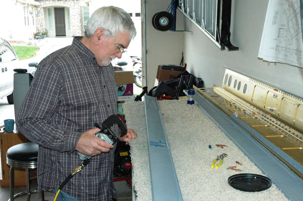
So, like the thousands of other RV builders, I stared at a pile of parts that someday will provide the lift for my airplane, especially the two wing spars. Not something you really want to mess up, so I spent much time, both before and after the kit arrived, looking at plans and some good websites. Then, finally, this past Saturday I got started.
The first task outlined in the plans is to attach nutplates (or platenuts) to the aft side of the spar caps that will allow the wing fuel tanks to be attached to the wings.

The plans tell you to rivet the nutplates into position, then use the nutplate screw hole as a pilot guide for countersinking the screw hole. Some guys do this process a bit differently, but it made sense to me so I pushed on ahead. Each of the rivet holes needs to be drilled out to size using a #40 drill, and the actual screw holes also need to be drilled out to proper size. Then, the rivet holes are countersunk to accept the flush rivets. Then, after the riveting is completed, the screw holes are countersunk to allow the flush skin of the tanks to lie flat on the spar cap. So, away I went, first doing some test countersinking on scrap and then carefully on the first hole.

Once I was satisfied with the setup, the very numerous holes were drilled and countersunk, then the nutplates were clecoed into position. Then the flush rivets were set.

Here is the spar cap with the flush rivets set. The actual screw holes have not been countersunk. It is easier to set up the countersink for the depth of the flush rivets and then do all of them. The set it up for the screw holes, which I have not yet done. Soon.

Here is a view of the nut plates from the other side.

As long as the countersink was set up for the flush rivets, I went ahead and did the drilling and countersinking for the nutplates that hold the three access plates on the bottom of each wings. This was a straightforward process. The nutplates for the access panels are for #6 screws vs. the #8 screws used to hold the fuel tanks to the spar.

And that was as far as I got this past weekend, other than to look at plans some more, and do some preparation work for next weekend when I hope to complete the countersinking and then move on to the tiedown assembly that needs to be fabricated and attached to the spar.
February 8, 2010
The work I did this past week, actually this past weekend, continued the work on the main spars. Two K-1000-4 platenuts are riveted to the forward part of each inboard spar that, presumably, will be used later in the assembly process. Haven't quite figured out what will be screwed into these but Van's says do and I do. It is mounted with flush rivets on the aft side so a fuselage plate can lie against the spar later.


So, back to countersinking the nutplates on the spar caps to accept a #8 screw....you can either do some dimpling and use a cut off #8 screw to fit, or you can take the advice of those who have gone before and counter sink to 0.370 inches, or thereabouts. Sounds good to me, so I did it easy.


No pictures here, but I also took the AOTWHGBM (Advice Of Those Who Have Gone Before Me) and drilled, mounted, and countersunk the K1000-06 nutplates for the six access cover plates that later attach to the spar...that would be four holes times six plates...the holes are countersunk for the #6 screw which, it turns out, should be less than 0.3125 inches. Done and done.
Okay, move on to the tie down assembly. My secret machine shop machinists guys helped me with cutting the spacers from the AEX stock. These spacers are mounted to the tie down assembly and, later, bolts go through them to hold on the aileron bellcrank brackets. Cool. Ailerons. Anyways, cut to rough size here.

And here we are trimming the 1/16 of an inch off the tie down assembly itself. Easy as country cookin'. How could I mess this up? Just wait and see.

Okay, we got tiedown assemblies and we got spacers pretty much ready to go.

Now, I got to play with a new set of tools that Santa, well, actually wife Lisa, gave me for Christmas. I needed a 3/8 inch tap to put the threads in the bottom of the tiedown assembly to accept the tie down ring. Needed one tap so I really needed a big tap and die set. Airplanes, at least this airplane, are done the old fashioned American Standard way, not that newfangled metric way, so I have a nice Sears Standard tap and die set. Unfortunately, the cars are all metric, and most of the rest of everything in the world is too, but that's okay. I like American Standard.

So, I might have tapped something in 8th Grade metal shop. Can't really remember that but I sure welded some stuff back then. Anyways, here we (that proverbial we) are tapping the threads. Followed the directions, worked slowly, worked great. Cool.

So, here is the result with the special Van's eyebolts..err...tiedown rings all screwed in nicely.

With all that done, we move on to drill in assembly the tiedown assembly and the spacers. Taking AOTWGBM, I used a liberal amount of tape to hold the spacers and protect the spar, etc. At the upper right is a carefully measured and drilled hold that, with an AN3 bolt, properly positions the tiedown assembly on the spar, then it is squared up with the spar and clamped into position for drilling.

A few clamps and clecoes later, we have drilled.

Take it all apart. Okay, that one worked out okay. Good to move on.

Now nut plates are mounted on the tiedown assembly and the spacers and tiedown assembly and nutplates are riveted together. Here is the assembly clecoed for drilling and riveting.

When all was said and done, I tried to test fit it all back together and found, woe is me, that the fit was too tight: the two spacers had to have a bit of material taken off to make the fit without damaging the spars. How could that have happened? Not sure, because all the holes lined up quite nicely. Oh well, a bit of sanding and a Scotchbrite wheel made things happy.

Okay, all primered and pretty much done...fit back into position and soon to be bolted to the spar along with the bellcrank brackets that go on the other side and bolt into the nutplates.

So, this shows me working on the right tiedown assembly. What about the left one? Well, just to remind me how easy it is to make a mistake, I decided to mess up on the one for the left wing. When I test fitted it after the pilot hole was drilled, it seemed far off from where it should have been. No problem, I must have drilled the hole off a little bit, so a bit of trimming of the overall length should take care of that. Trim it quickly, now, before I think about it. Then realize I had test fitted the left assembly on the right wing. Didn't need any trimming but now it was too short for where the tiedown ring needed to mount to the bottom of the wing. Stood there for a bit. Later ordered a new part from Van's. $4.30. Plus shipping. Plus delay. Plus just a bit stupid and/or hasty and/or, I guess, normal. Lesson learned (again): if it is not working right, think about it for a bit.
I'm in town for the next week, possibly two, so move on to spot prime the spars, do the left tie down assembly (when it comes), and start on the rear spar prep work.
February 15, 2010
Started and ended this past week finishing the main spars. I primed the countersunk holes on the top and bottom of each spar with my handy Napa 7220 Self Etching Primer. After I did this I realized I'll do it again when the skin is match drilled to the rivet line just aft of the nutplates and each hole will be countersunk to accept the dimpled skin. Oh well; just follow the directions.

And then it was on to the rear spars, which consists of a long "Z" shaped section with a large doubler plate at the wing root and a second smaller doubler plate riveted in assembly to the first one and the Z shaped section. Also, a thinner doubler plate is attached where the aileron will mount, both inboard and outboard at the tip. I pulled all the parts out and started to make some sense of them.

It was a three-day weekend for me, and my replacement tie down part came on Friday from Van's so I worked on that also. Here are the spacers fitted on the main spar. Because I had the issue of the spacers being a bit tight on the right wing, I added the masking tape here to provide a bit more room and hopefully ease the fit when the tie down plate is bolted to the spar. I ended up having to sand down the the other one to fit and I'd like to avoid doing that again.

And here we go tapping another 3/8 inch, 32 threads per inch, for the tie down eye bolt. Went smoothly.

Then back to the rear spar. All the parts have to be edge finished and then match drilled to the rear spar web "Z" channel. Here are the two thick inboard doubler plates for the right side clecoed together.

Here is the process of match drilling the two inboard doubler plates onto the rear spar web. Several ribs will eventually mount onto these plates.

Clecoed and match drilled...good to go.

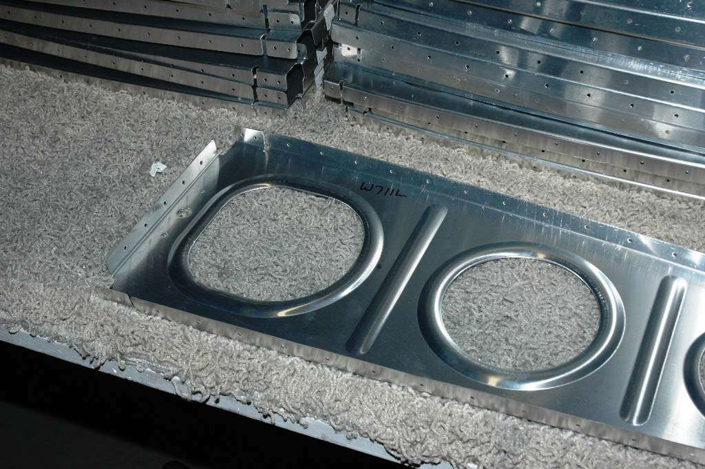
The aileron reinforcement plates are undrilled so they have to be clamped to the rear spar web and match drilled. They are the same shape as the rear spar and nest into position. Simple enough. The aileron push rod will go through the opening in the middle of the plate. It is cut to the proper size on the spar web but has to be added to the reinforcement plate and cut to the same shape and size.

Drill a few holes with a #30 drill as pilot holes and then use a unibit to carefully enlarge them. I was careful not to go to far because the whole thing is then clecoed back to the spar web and trimmed using, in my case anyways, a Dremel with a small drum sanding attachment.

So here it is trimmed with the Dremel tool to match the spar web opening. I then used the Dremel with a small Scotchbrite attachment to finish it off. Had to do this on both rear spars, right and left.

So, the basic prep work on the rear spars is now completed. Each spar then had to come apart to deburr all the match drilled holes and then do the preparation work for some priming.

Off to the paint shop for an application of primer. Tried not to get to heavy on this stuff. Not even sure why I'm using it...I think all that is really necessary is to get the parts that were cut out or trimmed...the holes and edges where the alclad was penetrated. Even that probably isn't really necessary for the environment this airplane will be kept in. Still, I press on and lightly prime all the parts.

Back to the main spars, I completed both of them by attaching the tie down mounts and the aileron bellcrank brackets (the two parts are mounted to each other through the spar). All the AN-3 nuts were torqued to the requisite 25 inch-pounds....not much. I added 2 inch-pounds for nut drag or whatever. Not much of a consensus on adding that but it would seem to be most correct. How 'bout the bolts that go to the nutplates...no torque specs anywhere that I could find. So, 25 inch-pounds for those also...then used torque seal to mark them and let me know later they have been torqued and aid later inspections.

So, as I end this week, the main spars are done and the rear spars await riveting. I will let them cure for a couple days and hope to rivet them this coming Thursday. We shall see.

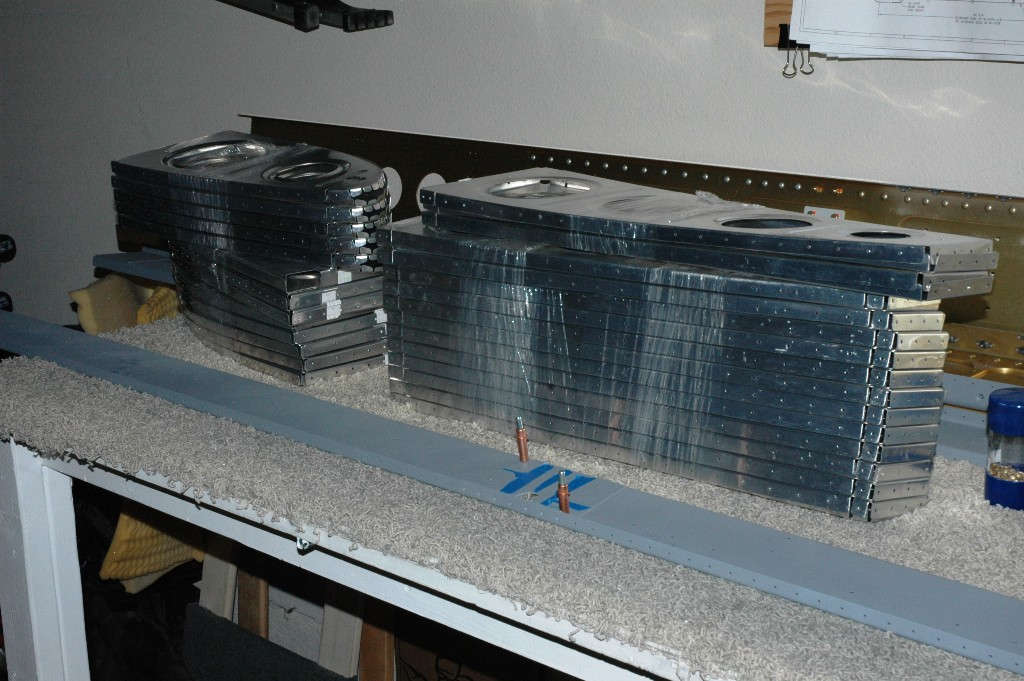
All the parts are laid out and waiting my riveting attention.

Meanwhile, I'll look at the stack of wing ribs over the next few days and sort them out. Next step in this process will be to do the rib prep. And, also, I shall draw up plans for a wing stand. I expect to build that in the next week or so and be ready for the wing framework to mount on them, hopefully in the next few weeks.
February 21, 2010
At the end of our last episode, we were ready to rivet the rear spars together. And, last Thursday night, that is exactly what I did. Studied the plans carefully, taped over the holes I did not want to put rivets into, then started the process.

I riveted the doubler plates on for both spars (same setting on the pneumatic squeezer) and, on the first doubler, did manage to put some rivets in some holes that were supposed to have been left empty. Well, the plans are a bit obscure in this area, for the open rivets are where some ribs attach and only if I thought about it would it have made sense. So, I thought about it for real and drilled out the rivets that were not supposed to be there.

Did better on the second spar. Here are the doubler plates riveted on with the AN470 rivets. Actually went pretty smoothly.

I riveted on the reinforcement plates at the mid spar and at the end of the spar, at least for one of the spars. I planned on having a friend help me the following Saturday so I left the second spar reinforcement plates unriveted. Figured he'd want to have a go at riveting. Figured right.
And, here, looming over the second rear spar, are the wing ribs. Every site I looked at commented on what a dreary drag it was to do the spar prep on all these ribs so I knew what was coming. But, except for a few of the on-purpose missing rivets, the four wings spars were complete and ready to go into the wing.
So, Saturday came and my friend Bill Reid came over to play. We've talked about this little project of mine and he's followed it with interest. He likes airplanes and has seen some other kit planes under construction. He's not a pilot but he has a motorcycle so that's almost as good as having an airplane. So, I lured him over on the pretext of helping. Little did he know we were going to do rib prep.
But, before we got into that, Bill did squeeze the remaining rivets to be done on the rear spar. He practiced a bit on some scrap and then went at the spar rivets like he'd been doing it for a long time. Spars are done.