|
The Project in Chronological Order From Day One Year One: 2009 |
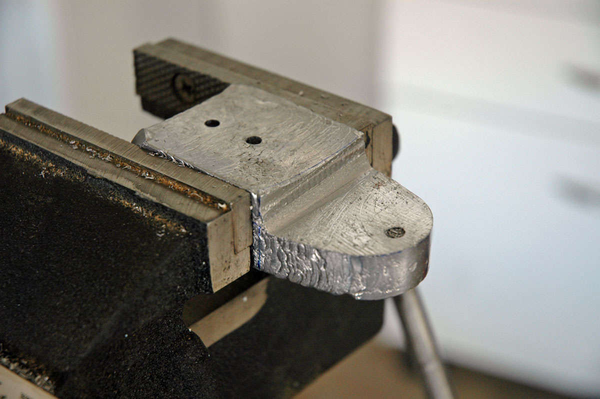
Okay, so where do we begin? Well, the empennage is a very fancy French way of saying "tail section" and it includes the horizontal stabilizer, vertical stabilizer, and the elevator and rudder control surfaces that attach, respectively, to them. Those building an RV-8 usually start with the empennage and, if you follow the instructions, you start with the horizontal stabilizer, which is exactly what I did.
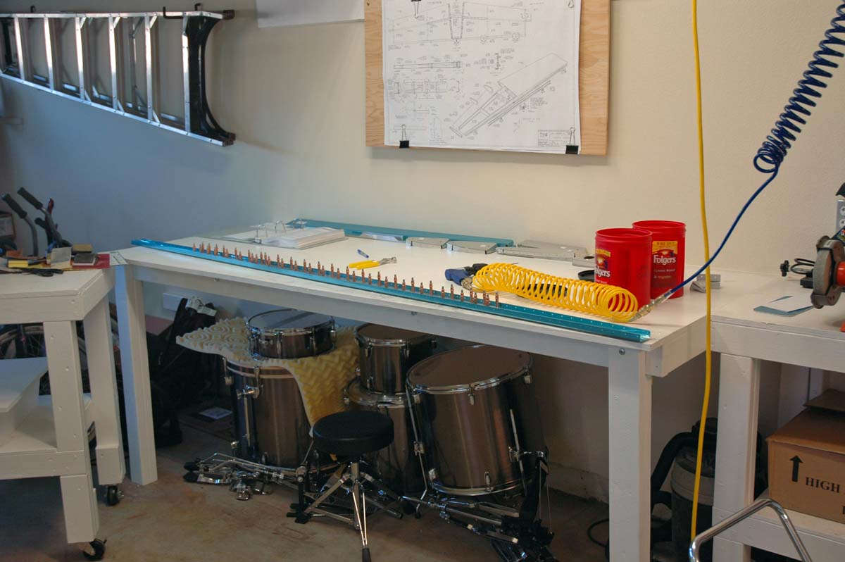
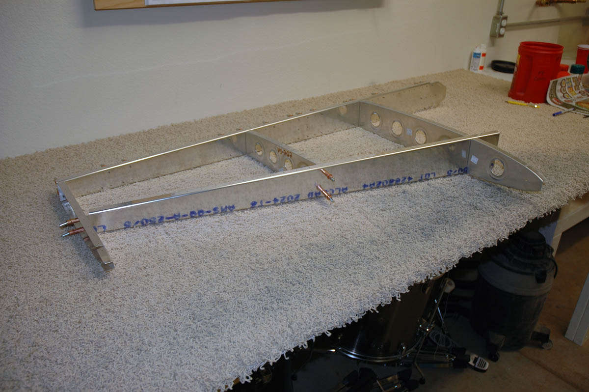
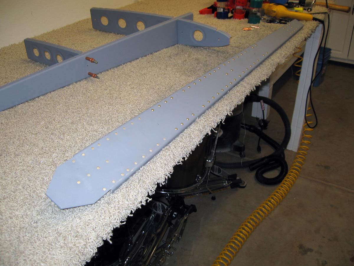
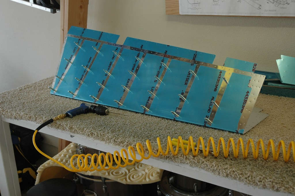
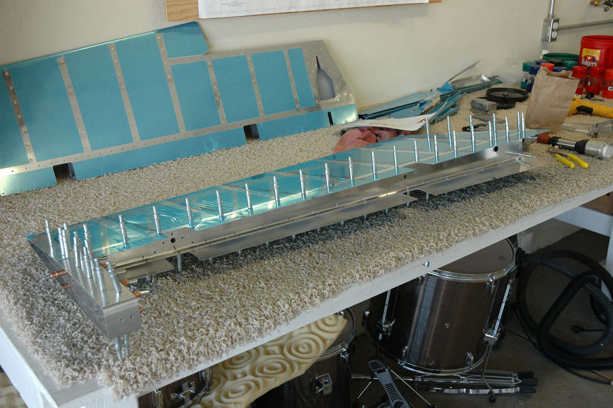
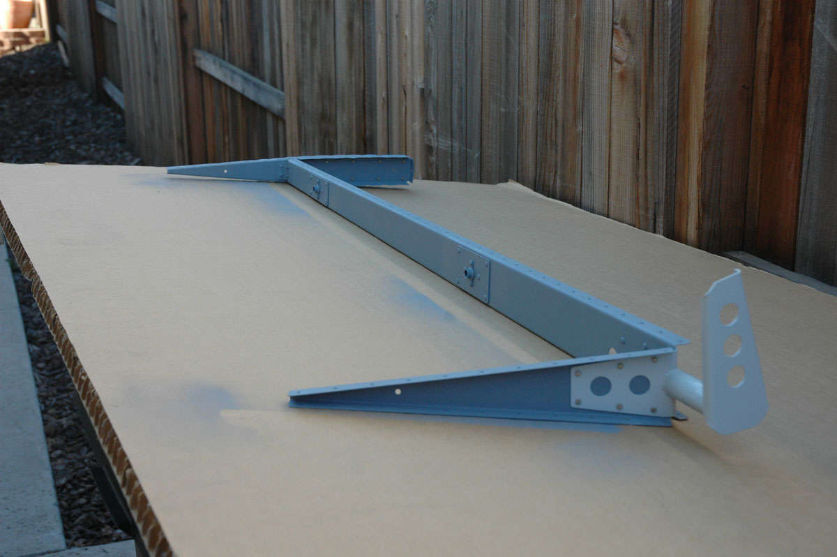
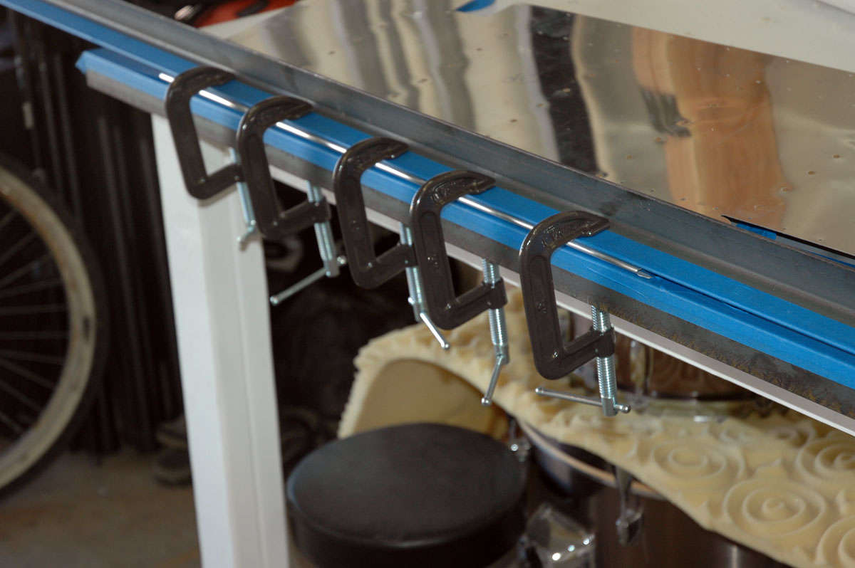
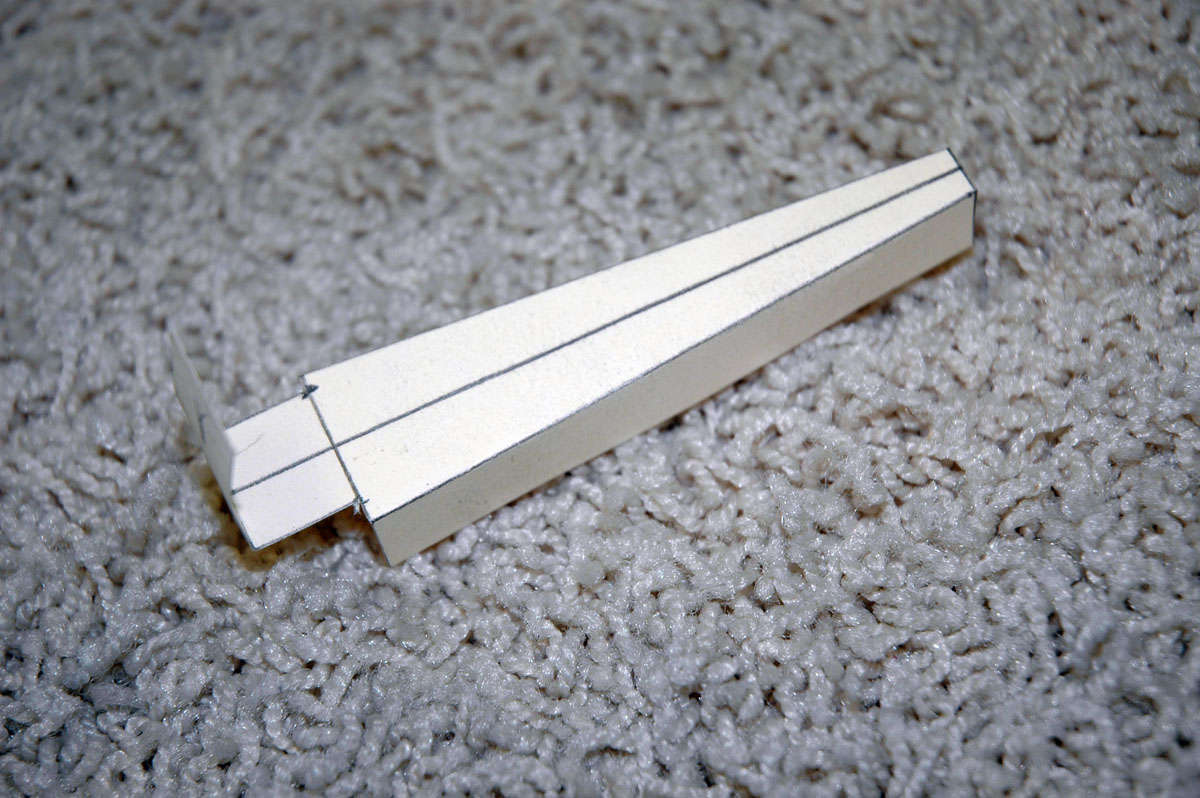
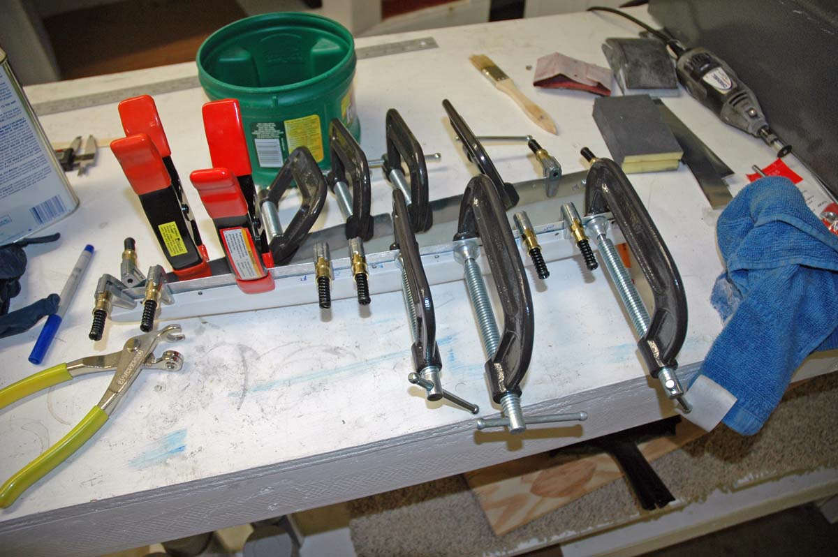
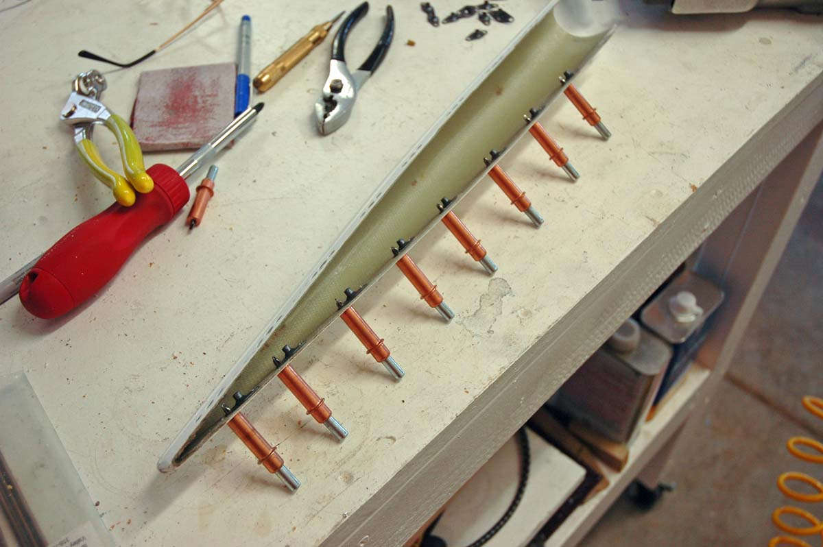
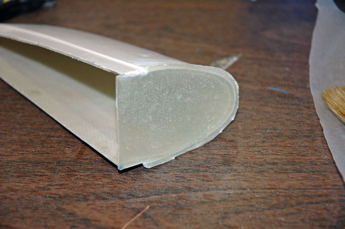
The RV-8 horizontal has two spars and each side, that is left and right assemblies, has three ribs, one at each end and one in the middle. It is a fairly simple structure that is a good learning spot, which is why it comes first. Fortunately, there are tons of resources to help you get it right, ones to pore over to figure out what this airplane building thing is all about. So, one cold (cold in Lincoln, California, is like 45 degrees, brrrrr...) January Saturday morning, I looked at the pile of parts and picked out, as per the instructions, the pieces needed to start the rear and front spars. The rear spar is assembled using a couple of milled pieces about five feet long that are riveted to a pair of stamped aluminum alloy pieces that, right and left, form the entire spar structure. So here is the basic assembly lying on my workbench:
And another closer view:
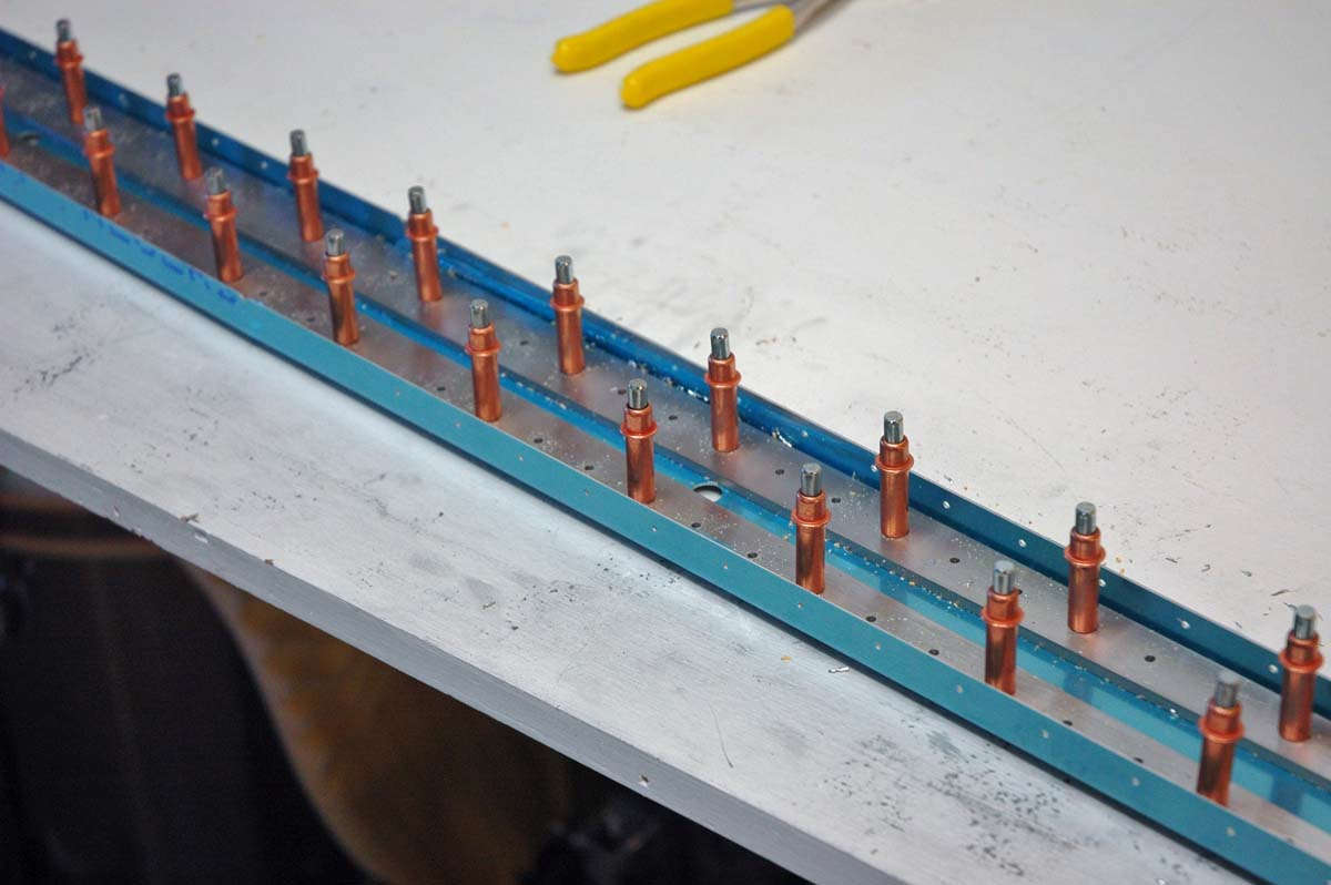
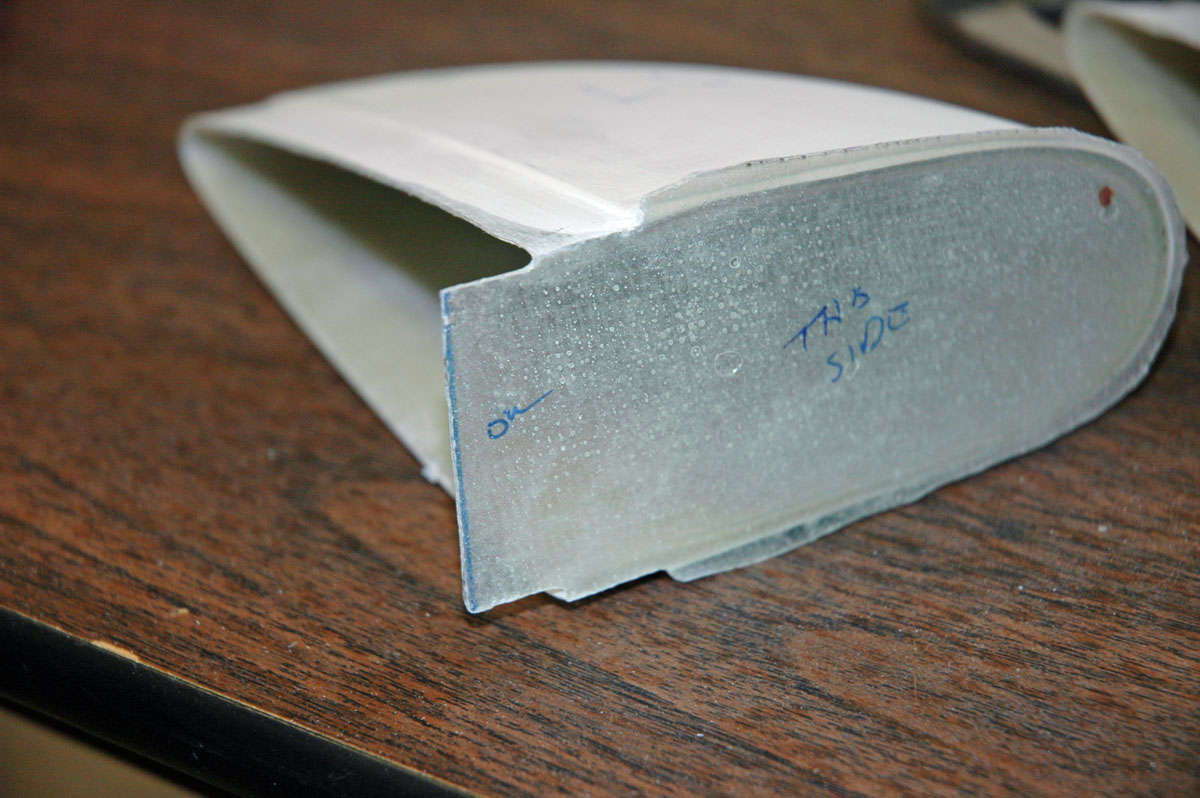
So, these milled parts have to be trimmed down for fitting and final drilled. Once the rear spar is trial fitted together it is set aside and work begins on the front spar. It is a bit more complicated as there are two milled parts that need to be prepped and actually bent to form a six degree angle to effect a swept front spar. This is slow going but enjoyable to just take a bit of time to figure out how to do it. It suits me.
Here you can see the two milled parts clecoed to the left and right formed aluminum parts. The blue plastic protective film is pulled back to allow access but still protect the part of the formed aluminum I'm not yet working on.
Here is another view but you really can't see the six degree sweep very well from this view. Trust me.
February 15, 2009
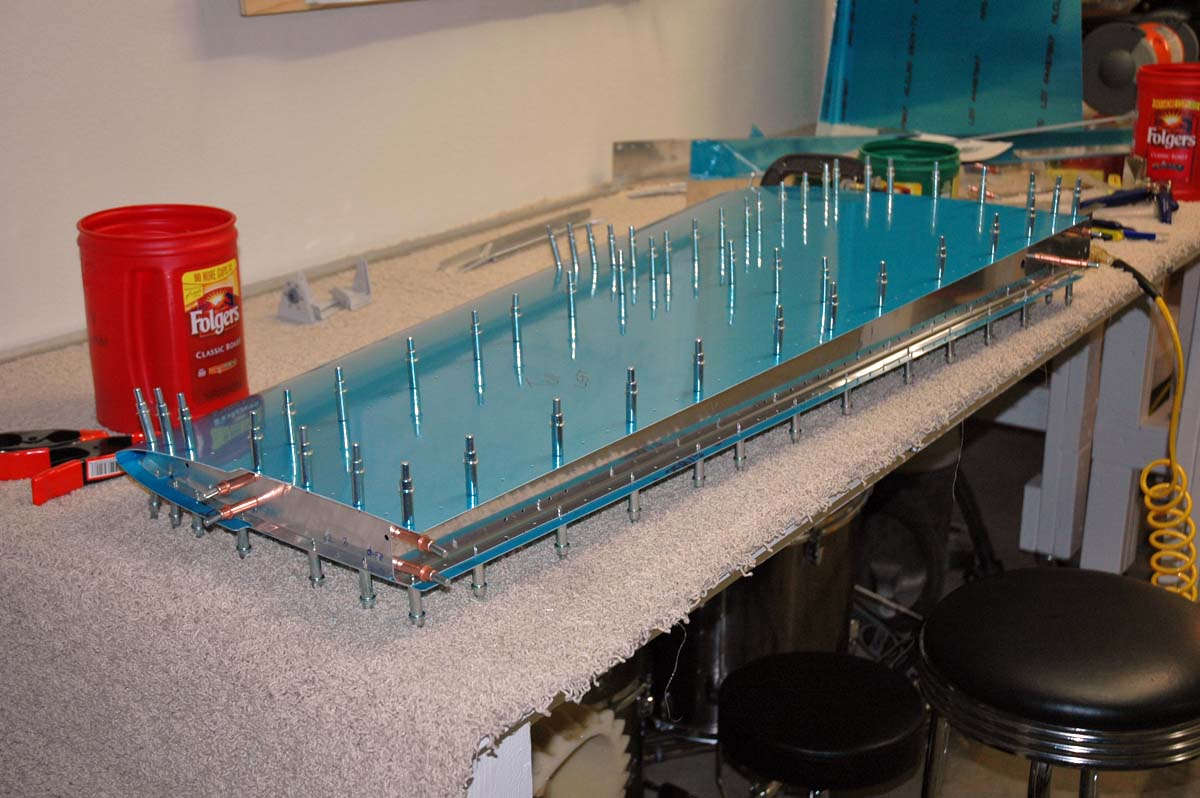
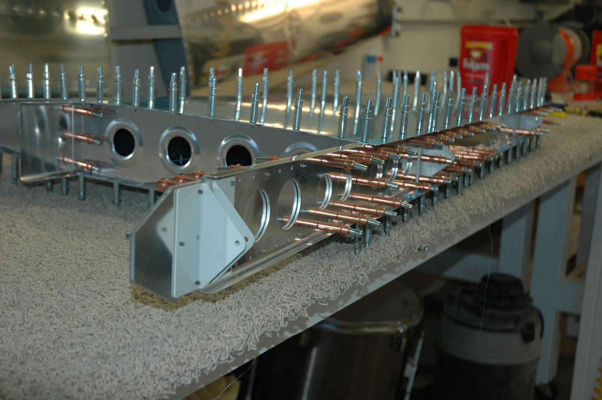
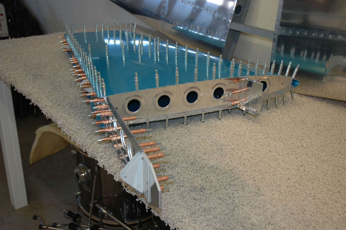
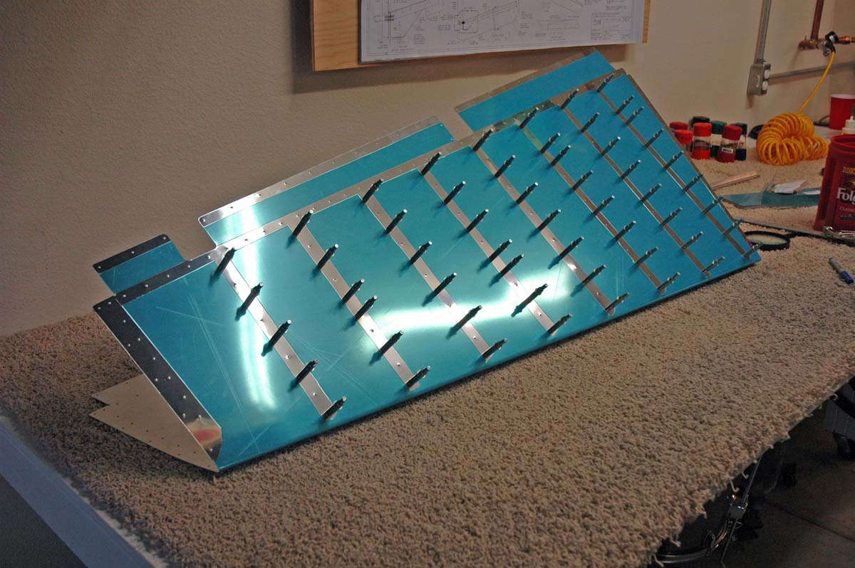
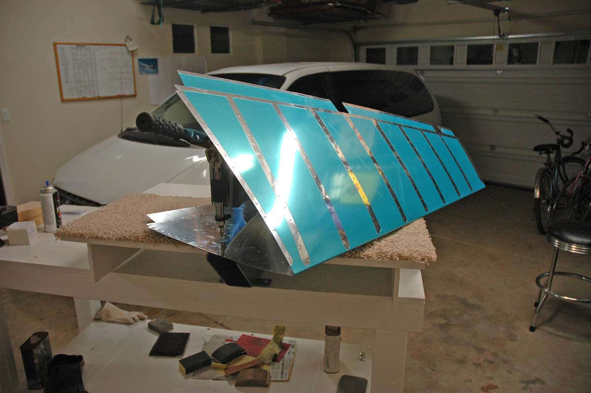
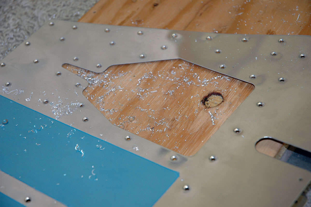
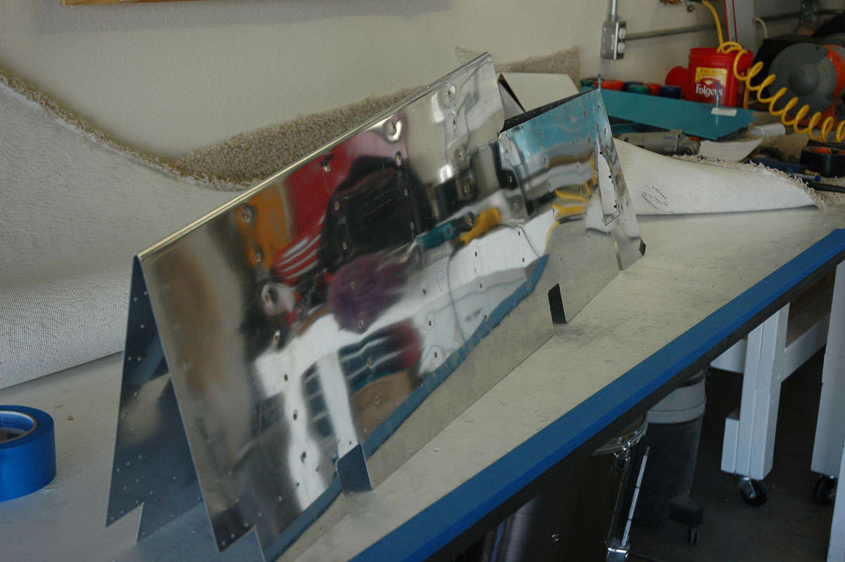
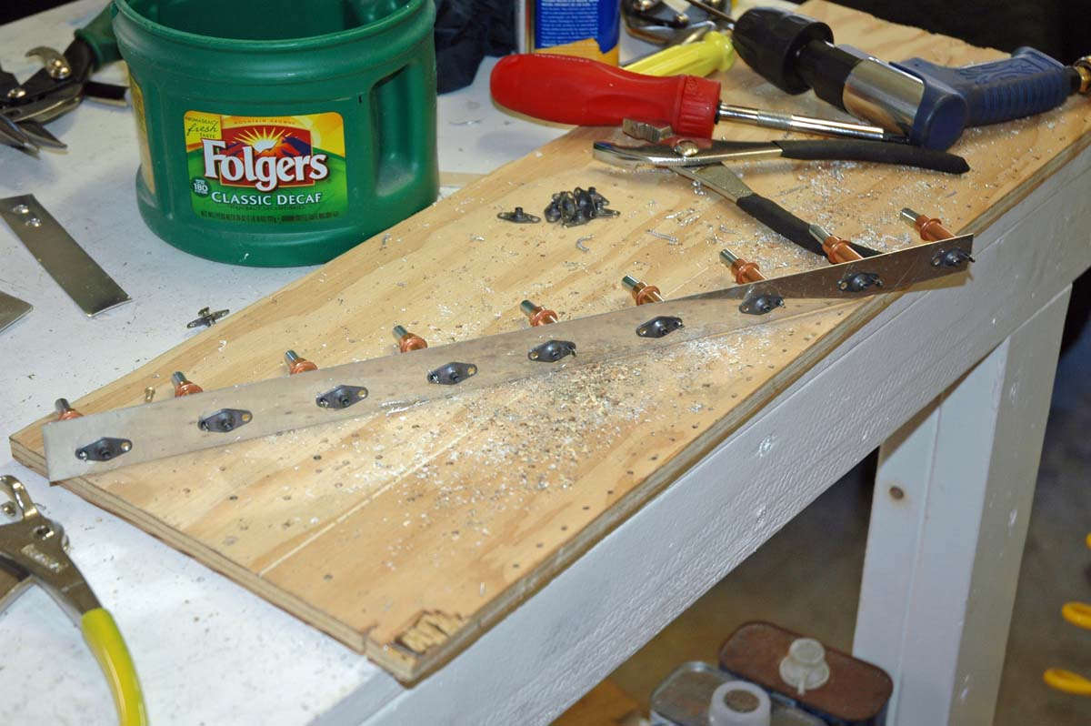
Well, slogging along here, flying for my job quite a bit. Just working on this assembly in between taking care of other things. There is a fair amount of work with each of the rib sections getting them trial fitted between the front and aft spar assemblies. Each rib is actually two parts...the rib section between the spars and the section forward of the forward spar that support the leading edge. All except the rib at the tip; it attaches the forward and aft spars and a fiberglass tip eventually is added. Anyways, after the tip and middle ribs are clecoed to the spars, the one-piece aluminum skin is fitted over the framework assembly, in this case the left side of the horizontal stabilizer. The idea here is to trial fit so the match drilling and final drilling of the skin can be done, as well as fit the inner rib into the assembly. Here is the skin fitted:
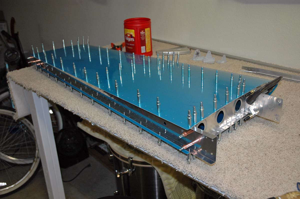
And from the other end. Starting to look like an airplane part.
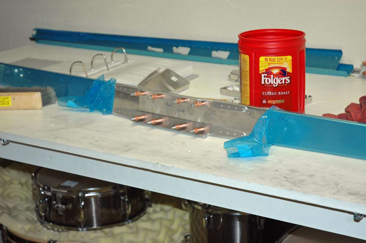
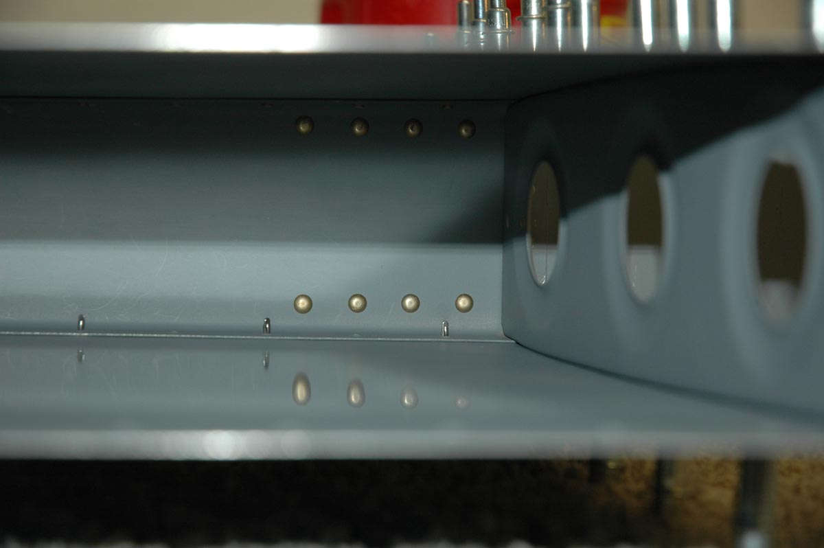
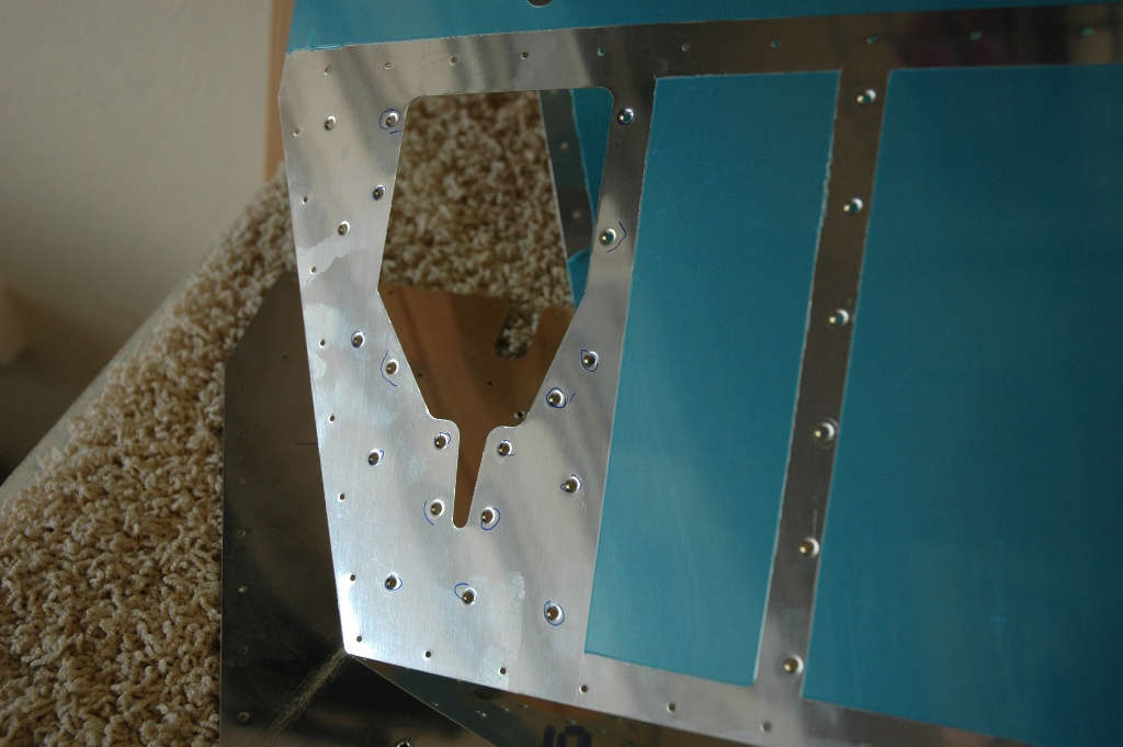
Okay, there is much care taken to insert the inner ribs into the assembly because the forward flange of the rib part that fits between the forward and aft spars will have four rivets inserted to hold the parts together, and the top and bottom of the four rivets have to go through three parts: the forward flange of one rib part, the formed aluminum spar part, and the thick milled aluminum structural part. The two middle rivets also have to go through three parts: the forward flange, the spar web, and the aft flange of the leading edge rib. Four rivets; not alot of room. Sounds hard, but the main idea is to make sure that each rivet has the proper edge distance so it can handle the design load stress. Lots of guys have had problems here by making the holes too close to the edge of the parts, so I measured like ten times and kept changing it around until it made sense. Over thought the whole thing. Final result worked for me, though, at least on the left side:
And a closer view of the forward flange of the rib section where it fits into the spar assembly with pilot holes drilled where the bigger holes will go when I get brave enough.
And then there is the challenge of wanting to put little airplane parts together when your Ford Focus has a leaking clutch master cylinder. Duty calls and the higher priority gets the wrenching. Unfortunately, the airplane has to take the last priority...kind of like family and job and household things and cars and emergencies and then maybe airplane construction. Bill Boeing had the same problem.
February 22, 2009
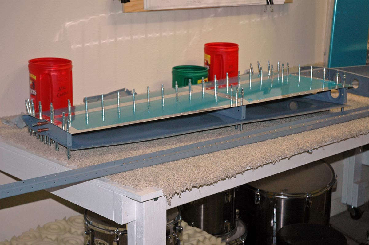
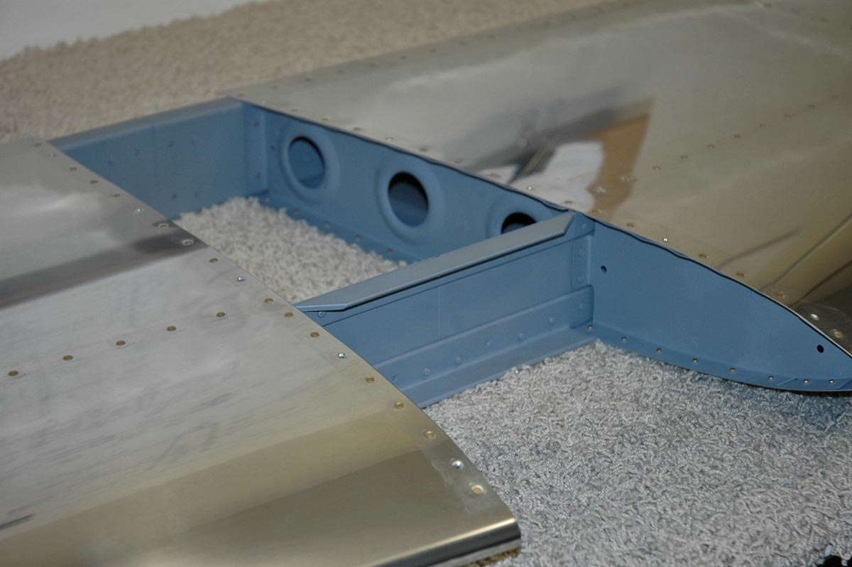
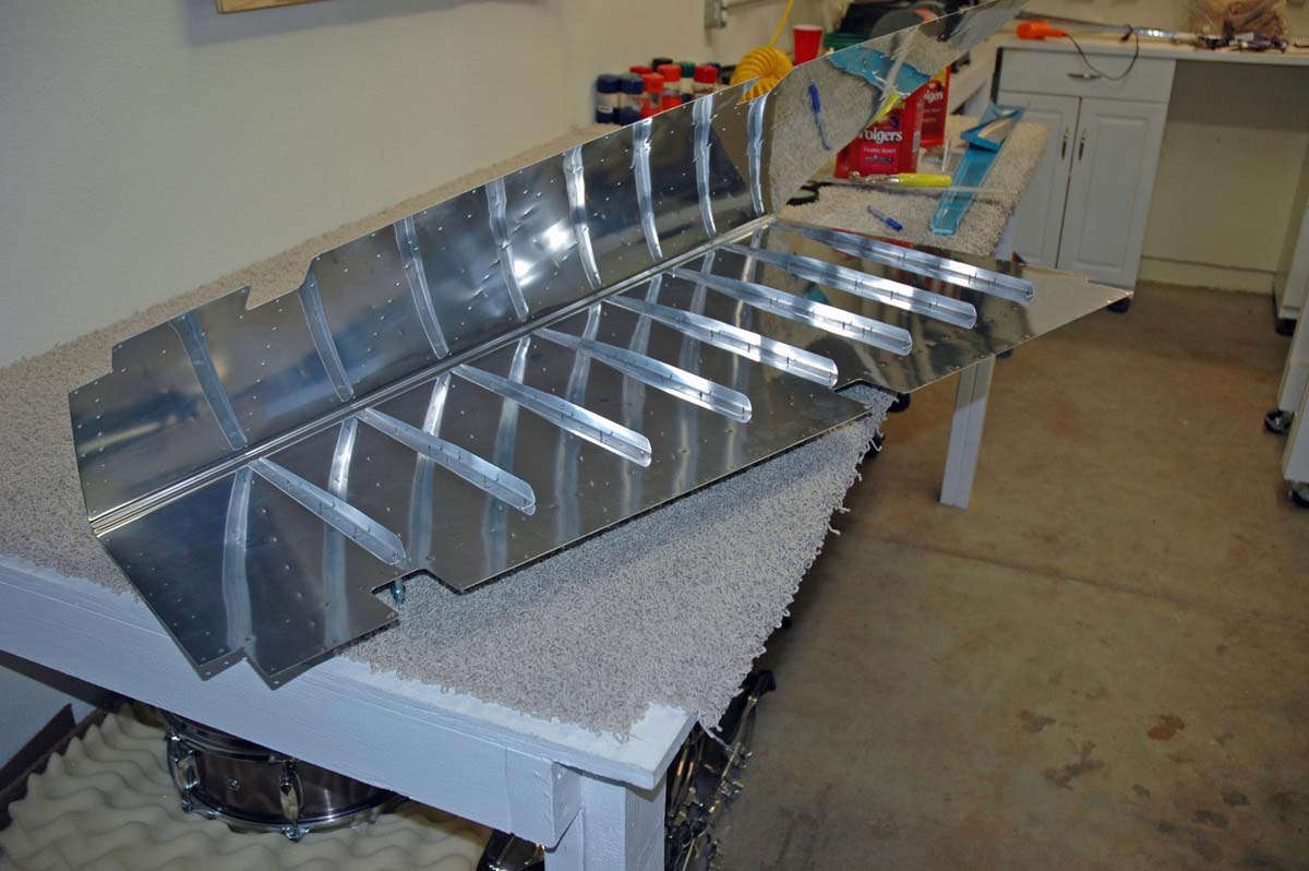
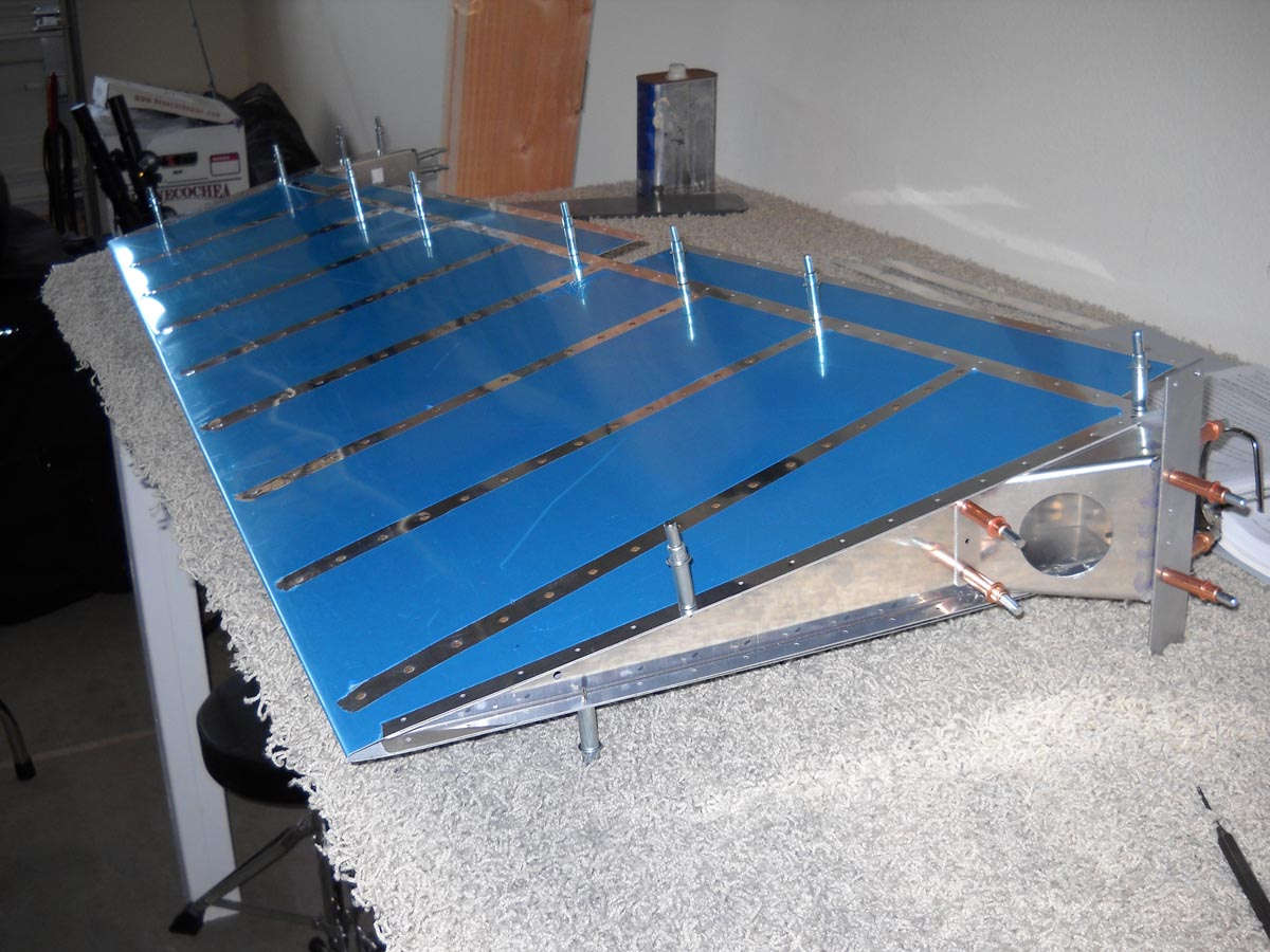
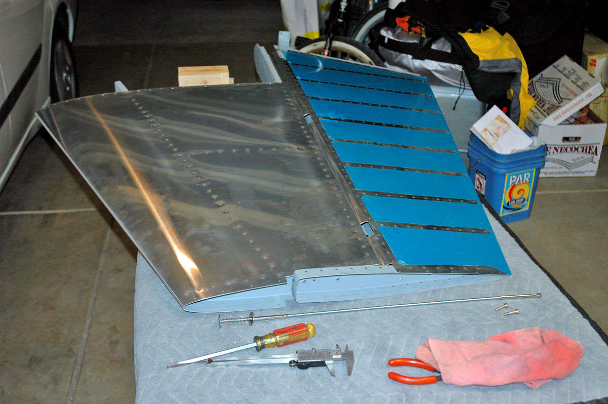
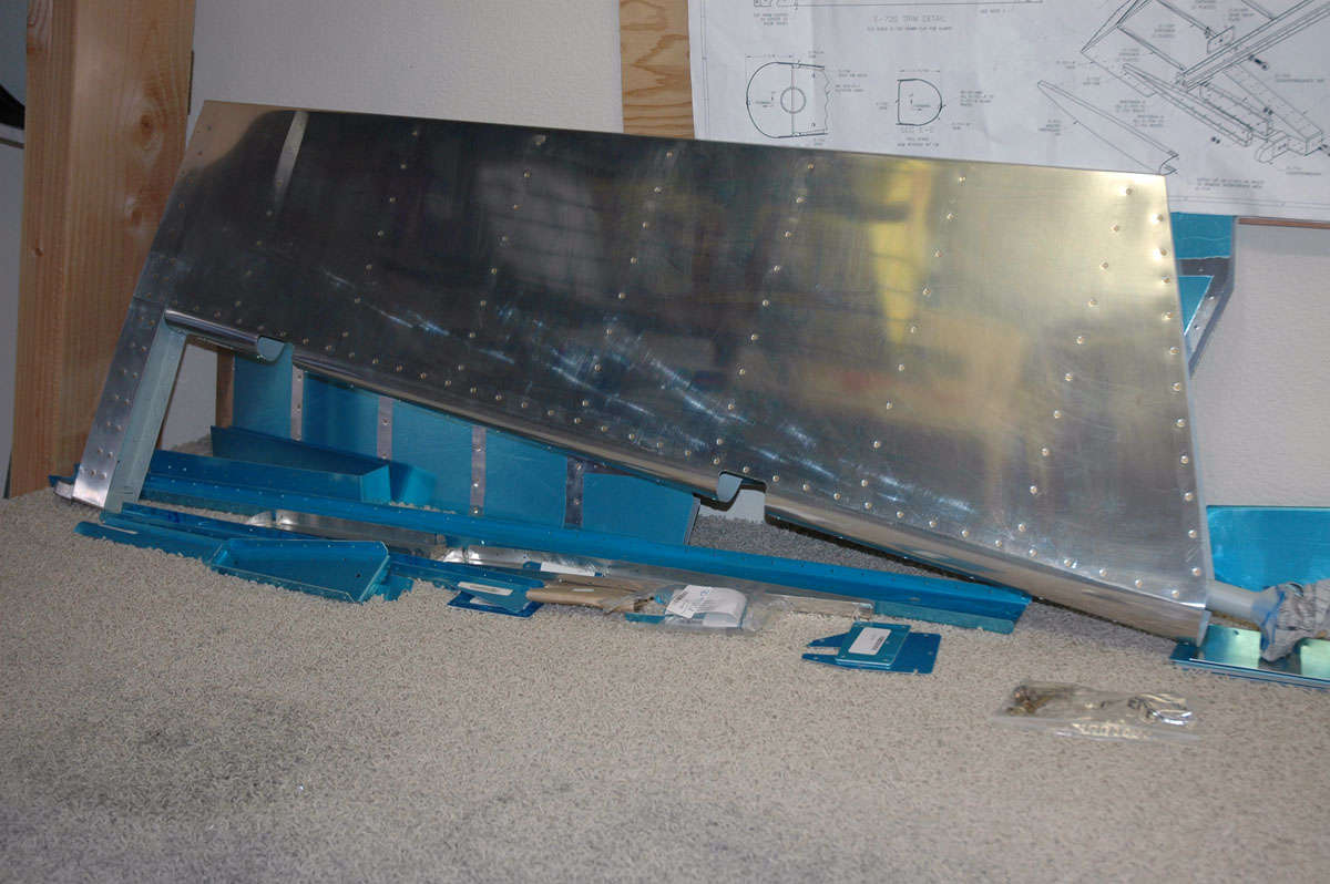
Okay, this week I continued to fit the parts together for final drilling and part preparation. Ended the week with the horizontal stabilizer in this condition, basically complete and ready for disassembly.
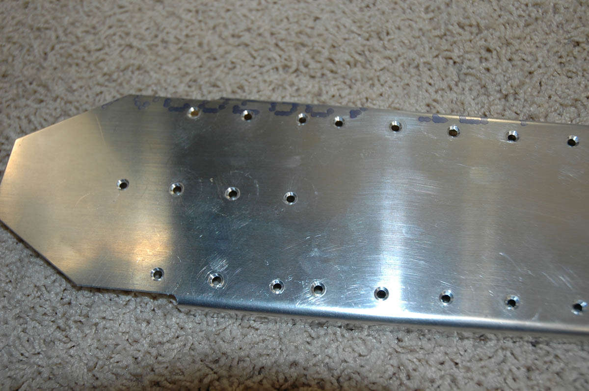
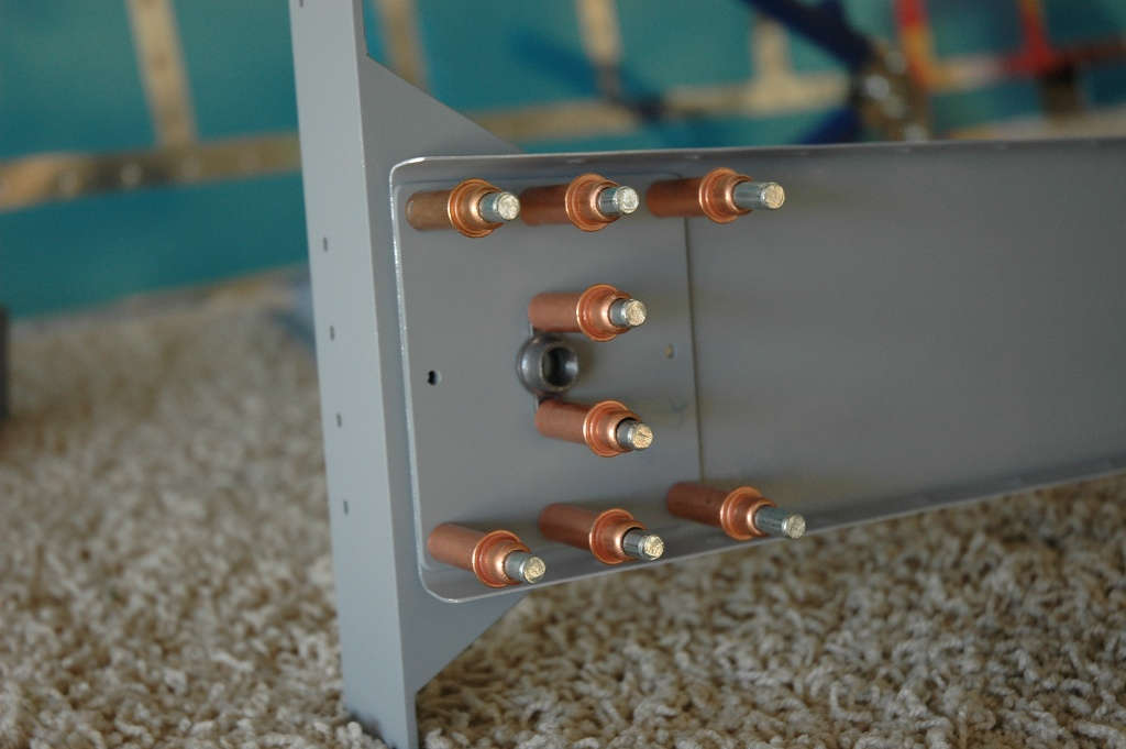
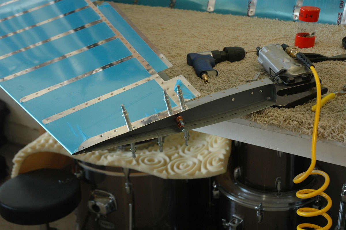
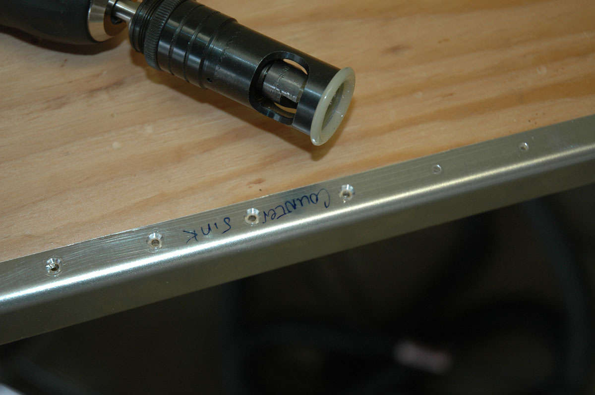
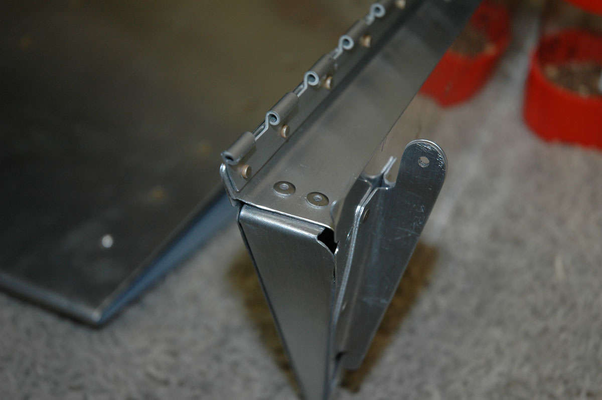
I did get brave and drilled the Mt. Everest of the Horizontal Stabilizer, that being the HS-405 forward flange to the forward spar. Turned out okay. This is the attach point HS-405 side (on the right horizontal):
And the other side:
And the aft side of the HS-405 where it attaches to the aft spar:
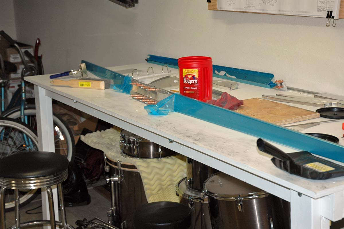
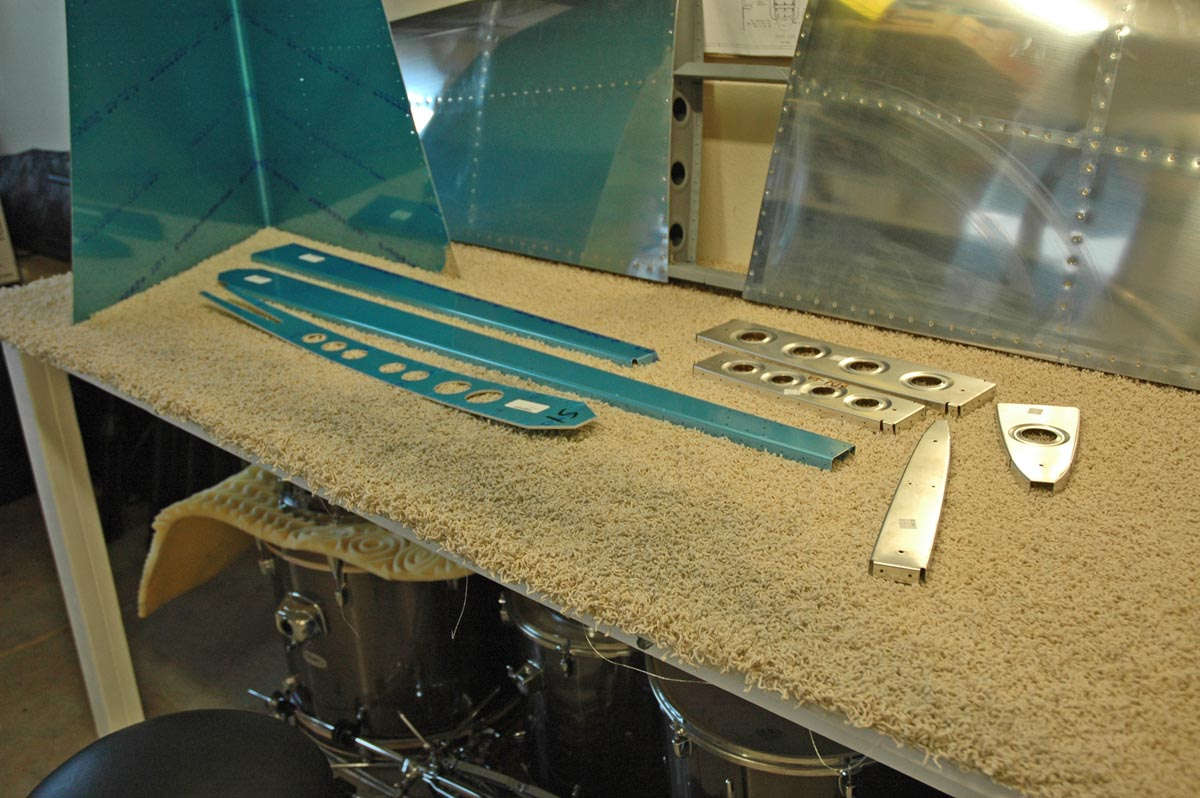
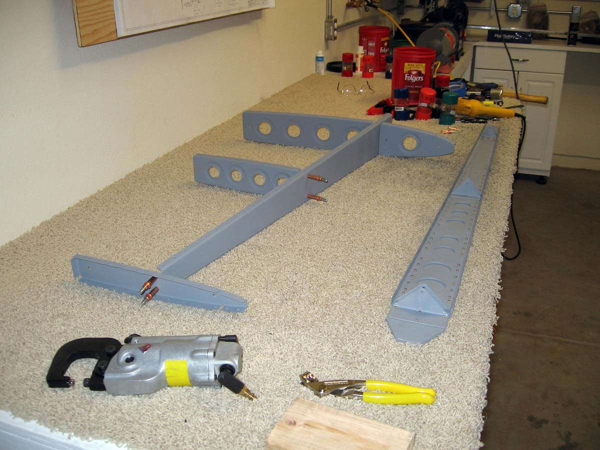
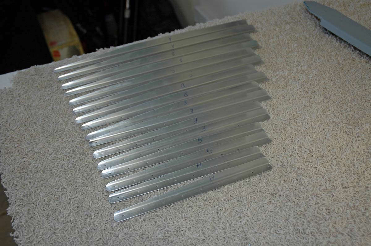
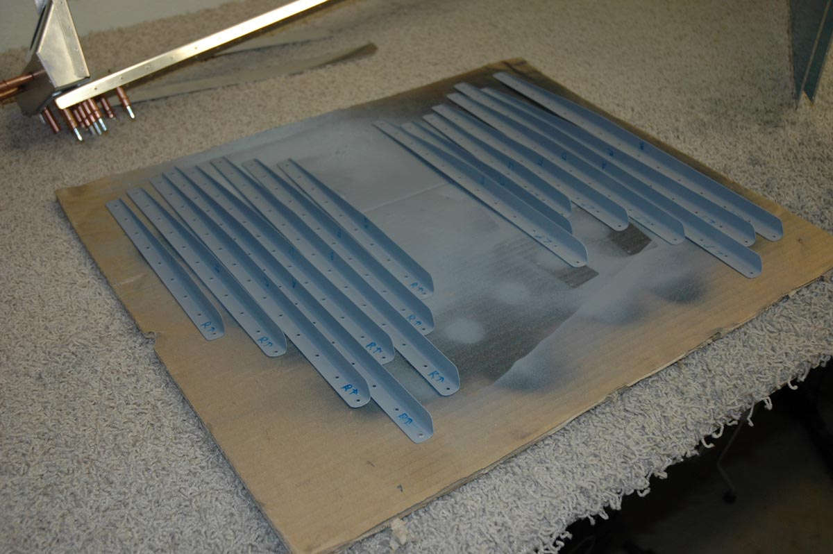
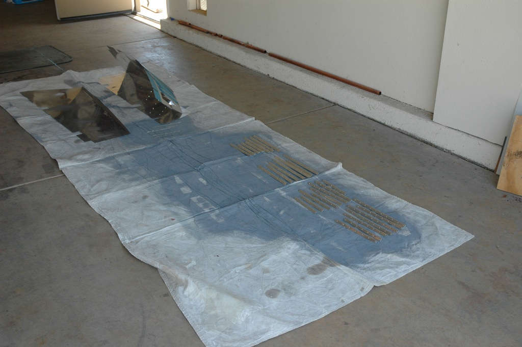
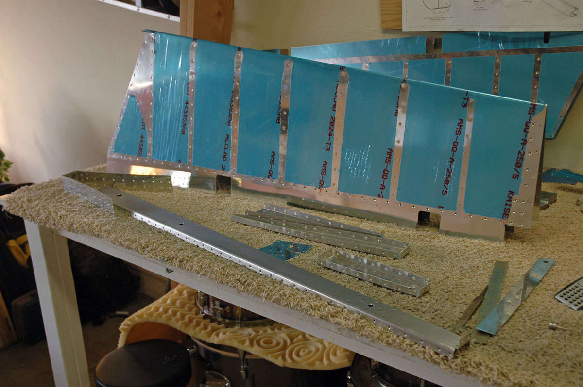
And then the whole thing comes apart and the various parts are prepped for actual assembly. Here are all the ribs and spar parts laid out because they are pretty. A bit of laborious preparation is now forthcoming. Stand by for deburring, and dimpling, and doing things to the sharp edges.
March 1, 2009
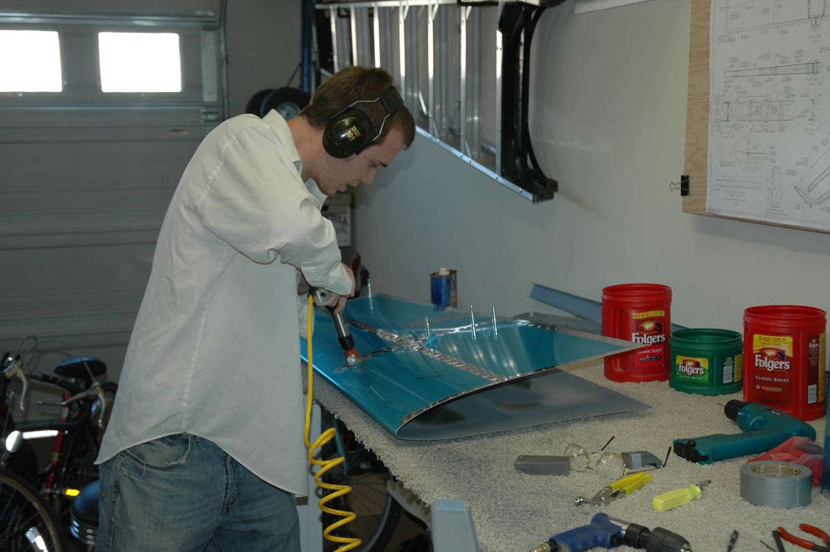
Spent a few sessions this past week working on parts preparations. This included deburring each of the holes, a process that uses a little tool to remove tiny burrs, or raised ridges of metal, that result from drilling a hole. The burrs can cause stress points and possible cracks later, plus prevent the rivets from sitting down in the holes all the way.
I also dimpled all the surface skin holes and the mating surfaces on the understructure. The dimpling allows the use of flush rivets, so the final skin will be smooth with much less aerodynamic drag than if raised head rivets were used. Of course, one needs to be careful when using the pneumatic squeezer to dimple holes as if one get a bit too quick the bugger will add a dimpled hole where one doesn't want one. One can get really disgusted with one's self if that happens. Especially if it happens twice.
One will need to add an extra flush rivet to fill the extra hole. One has also decided that if anyone asks, this extra rivet is to mount the optional digital elevator thruster dampner on the inner skin. They'll never know.
Got my son Adam out into the garage for a second set of hands to manhandle the skins while dimpling. He helped me on the right half of the horizontal stabilizer, the one that doesn't have the extra holes and the one that ended up with much fewer skin scratches.
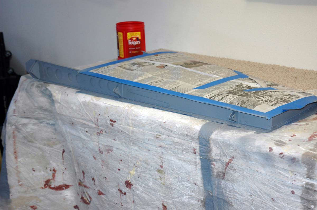
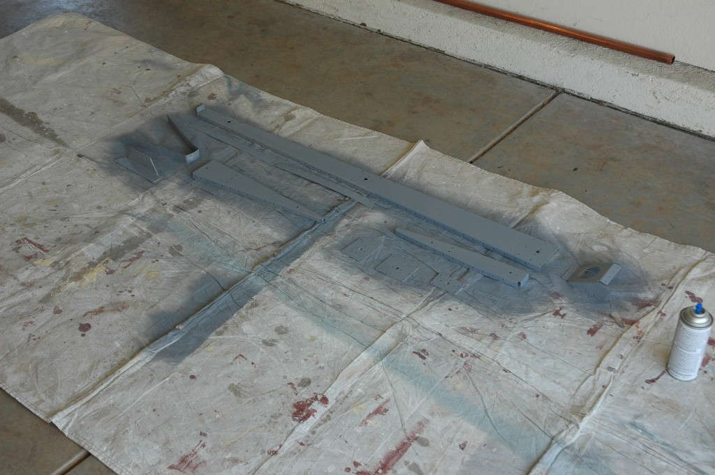
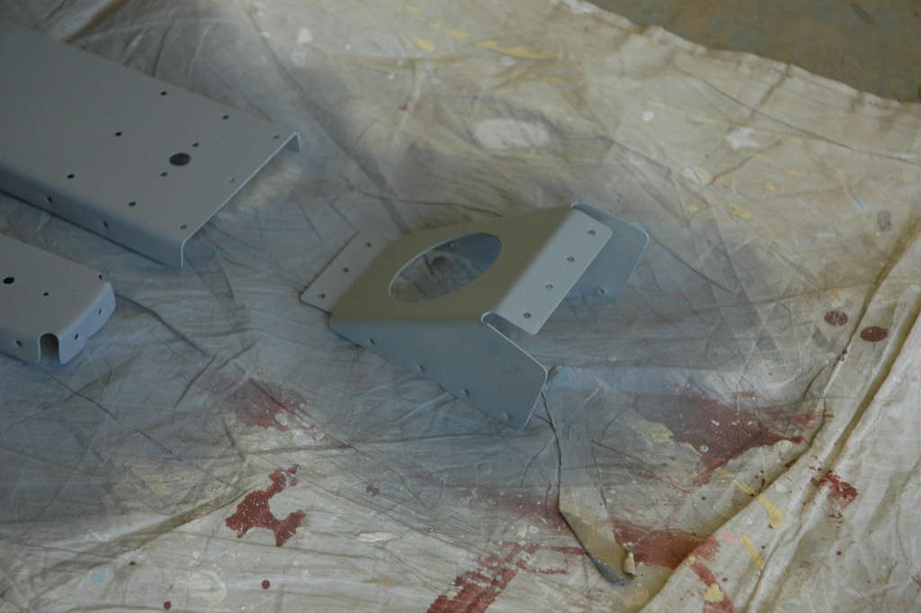
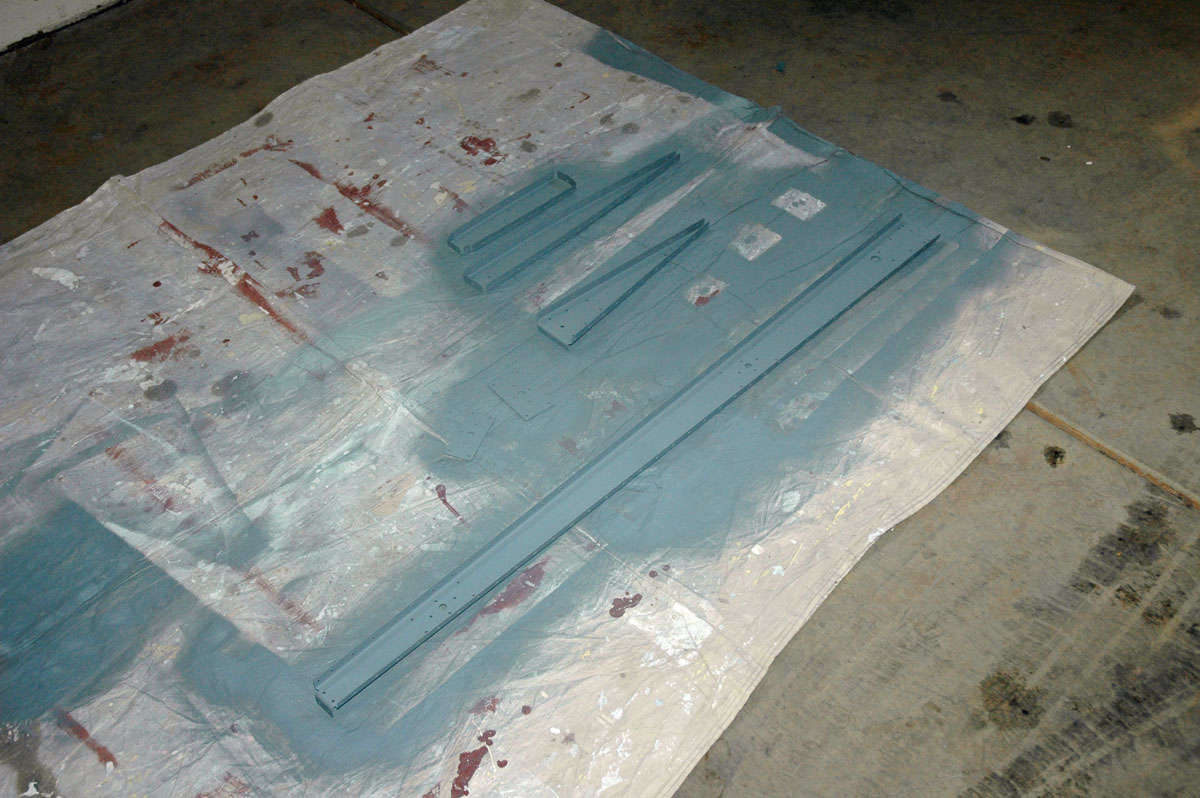
So, once deburred and dimpled, it's off to the paintshop which, it turns out, is about ten feet from the assembly line and is on the garage floor. I read and reread all about the "primer wars" and what to put on the inside structure to keep it corrosion free. I decided less is more, and will use a rattle can self-etching Napa 7220 primer. I did a bit too much prep work on the ribs so the alclad aluminum surface might be compromised. Prime all the components, as seen here, and learn to be a bit less busy on the vertical stabilizer and other parts.
As an editorial comment, I don't know nearly as much about this as the smart primer people, but for how these airplanes and, particularly, this airplane, will be flown, I'd rather not get too carried away with surface preparation. It's not like this thing will be flying in, like, the year 2512.
I also sprayed a bit of primer on the interior skins where the ribs attach.
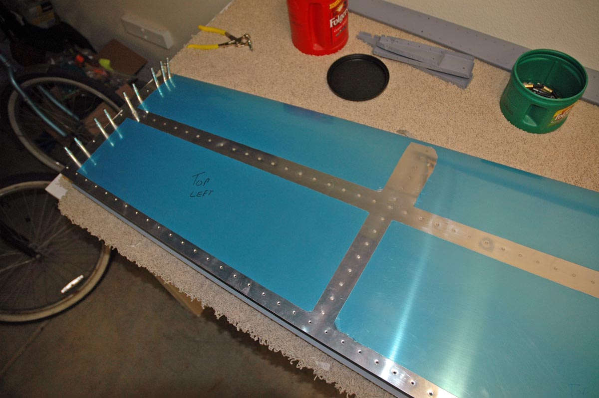
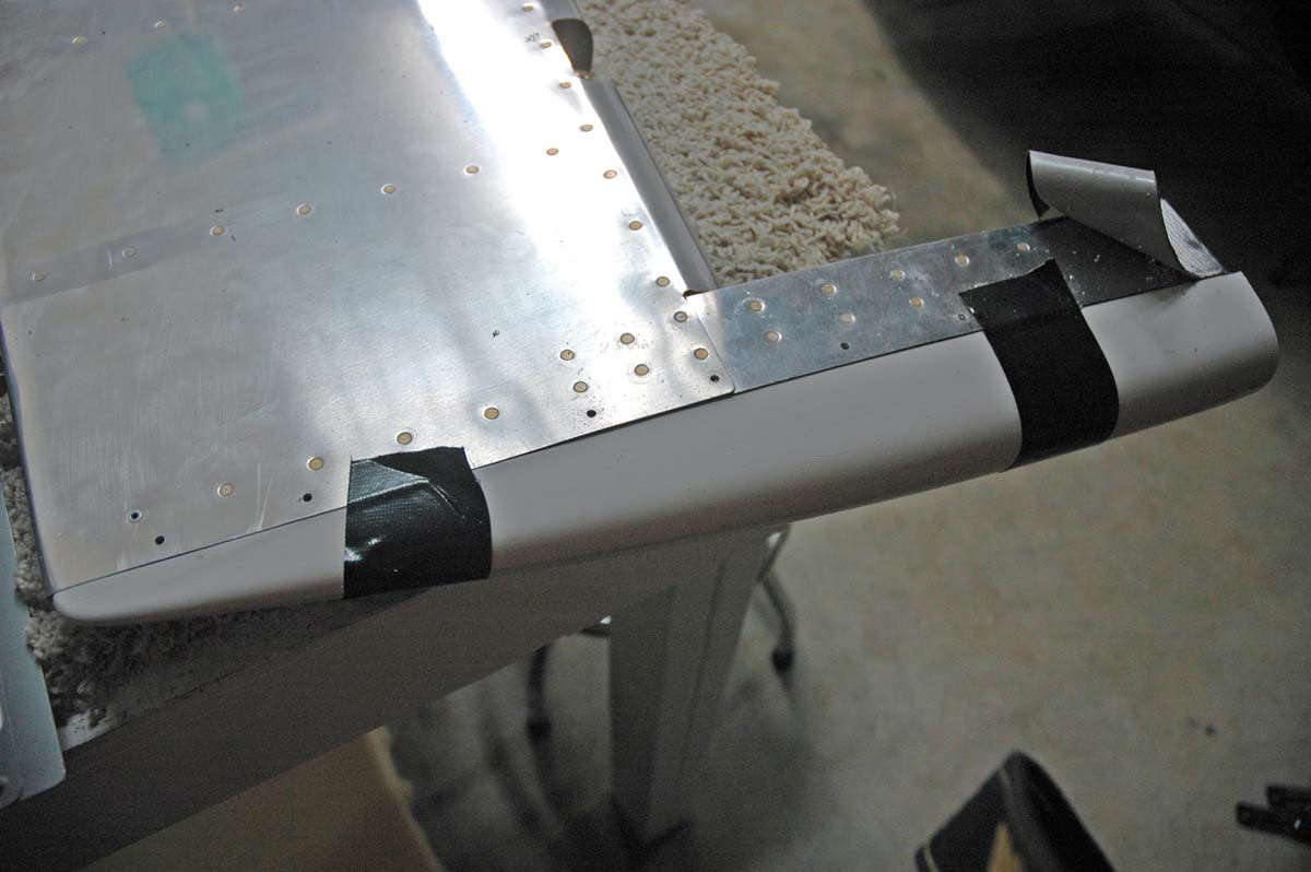
So here is one of the dimpled and prepped horizontal skins ready to go. I used a soldering gun to melt the plastic in such a way as to enable me to peel away the plastic film from where the rivets will go. It amazes me that some builders lay these rivet lines out with exactly straight lines with measured to the inch with rulers, a process that seems to take a lot of time and effort. I have to admit nice straight lines of blue film looks pretty cool but the point for me is to protect most of the skin through the riveting process. After the horizontal stabilizer is done, all the blue film comes off, so I'm not too concerned in my lines aren't straight.
By the way, the corner of the blue film in the one section is peeled back just to make sure my soldering technique doesn't scratch the skin. It mostly doesn't, but I need to be careful. So, after all is said and done, we are ready to rivet the horizontal stabilizer together. Next weekend, I become a man.
March 16, 2009
Okay, so two weeks go by like...poof....
Got to spend one weekend fixing a computer...that pesky blue screen of death syndrome. But I did get a few hours on the old RV-8.....up to riveting some serious parts together. Not a great job, but the learning curve is there and I'm climbing my way up it.
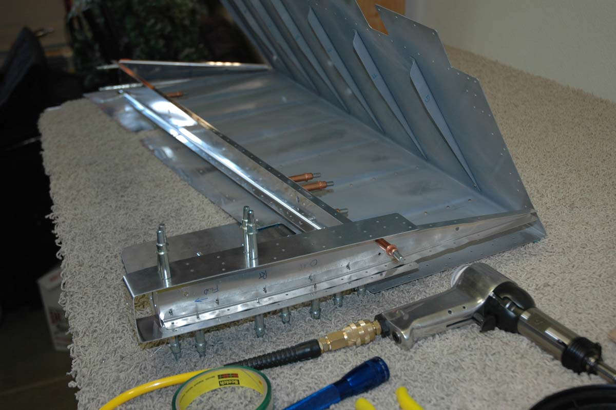
I did rivet the aft spar together...didn't take too long and only had a few "quality control" issues (as in drill the rivet out).
So, here is what I started with....the spar assembly is ready to be inserted into the right side of the horizontal stabilizer. I've already flush riveted the nose rib into the skin section, and then the spar assembly is slid into position.
Then that thing is clecoed together for riveting....
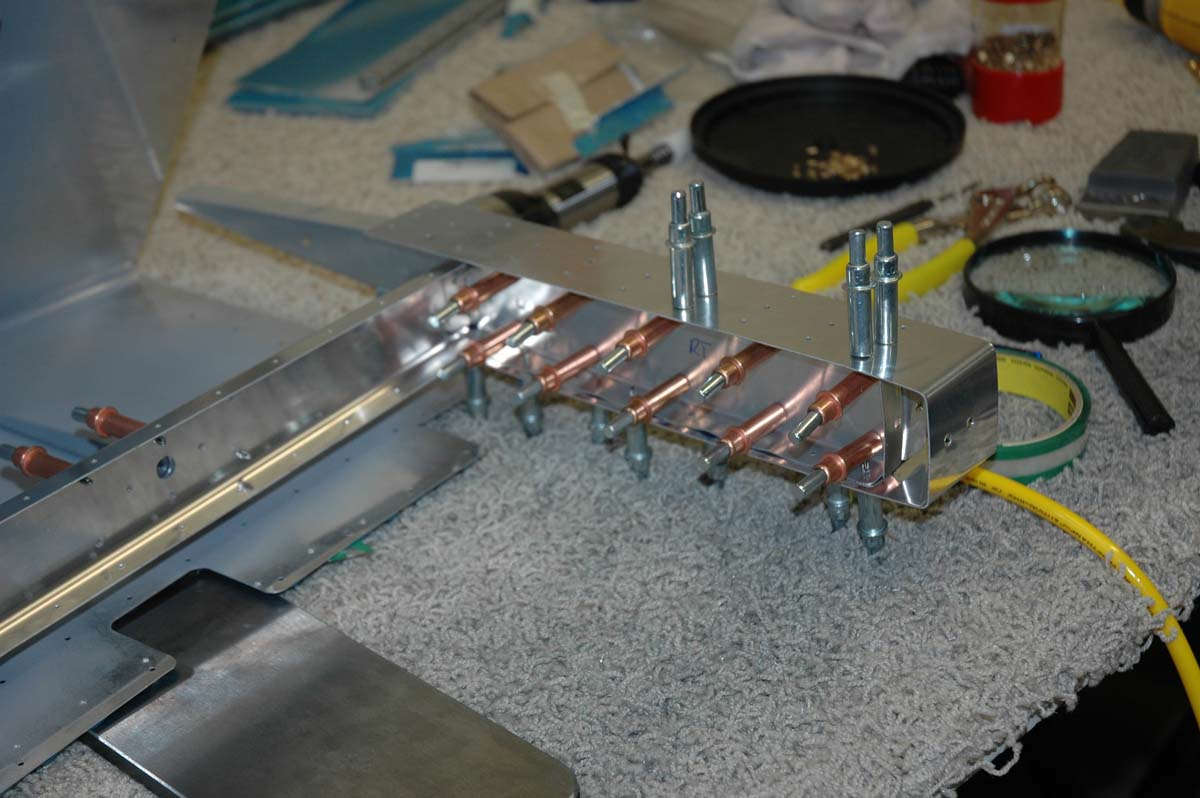
Here is one of my sons, this being Nathan, learning how to rivet. Where it takes two to tango, he was my partner for the day to get to some of the hard-to-reach-with-one-person rivets on that nose rib.
As is to be expected, the actual riveting doesn't take too long. Here is the right side assembly with all rivets in that have to be done with a rivet gun. The ones on the edges can be squeezed.
In the assembly process, that nose rib in the middle of the assembly is attached to the forward spar and the aft rib using pulled rivets. This is about the only way this can be assembled as there is no longer any access forward of the forward spar. So, it turned out okay, eh?
And, moving the camera eye to the right a bit, here is the aft side of the forward spar where it meets the interior rib...the one closest to the fuselage (someday).
So, the week to come, I hope to finish the horizontal stabilizer. Should come together okay, We shall see.
March 23, 2009
Worked off and on this past week on trying to finish up the horizontal stabilizer. It is just about there....just a few little bits of tid to complete.
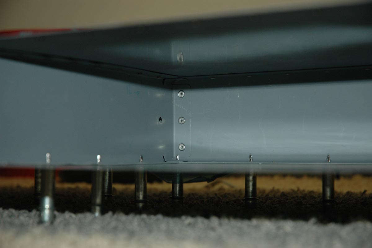
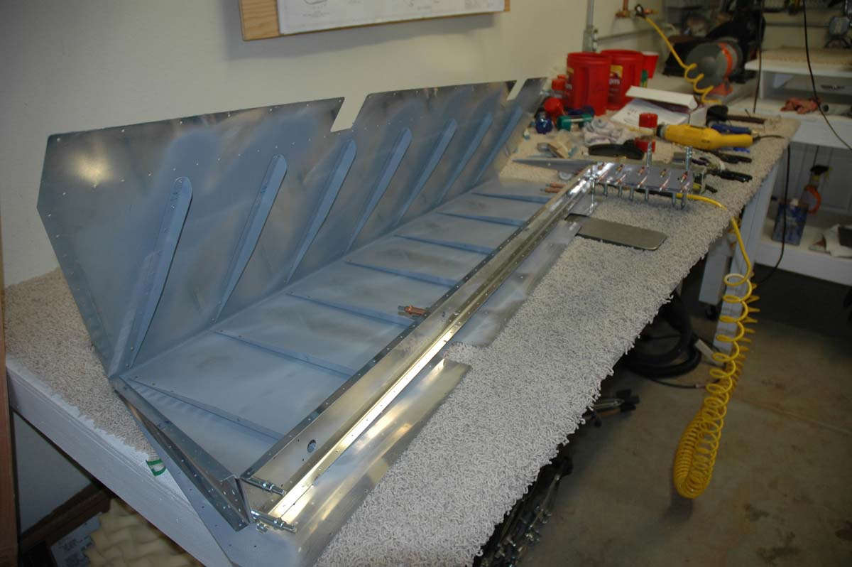
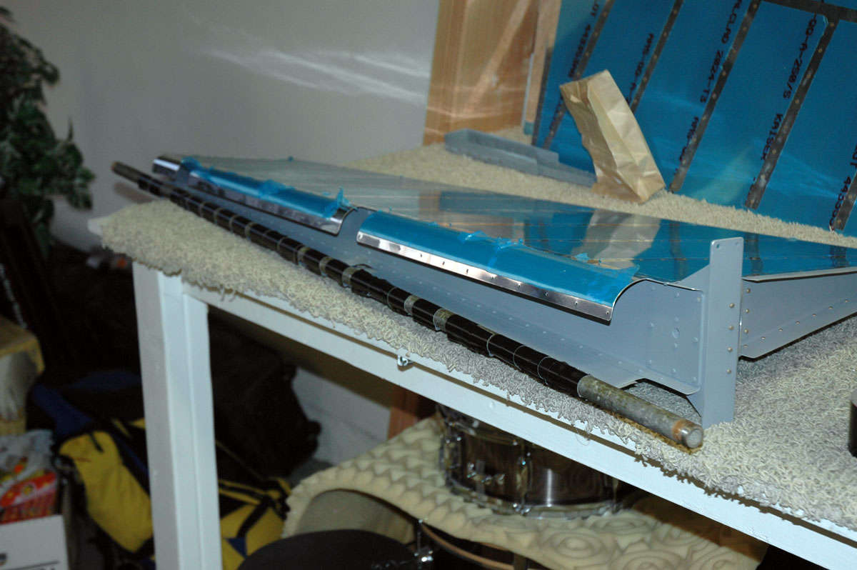
Here is the assembly with the interior rivets completed and with the aft spar fitted into position.
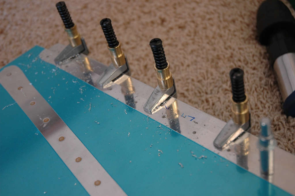
And another closer view. Every other hole is clecoed in preparation for starting the riveting. I had a bit of trouble trying to figure out how to use the pneumatic squeezer on these rivets...the part I wanted to be stable was the part that moved. Not as good control but I figured it out. Only had to drill a couple of out. I'm getting better at drilling them out. My technical assistance team (a bunch of excellent FAA mechanics that normally work on Learjets) gave me a few pointers...well, actually many pointers. And away we go....
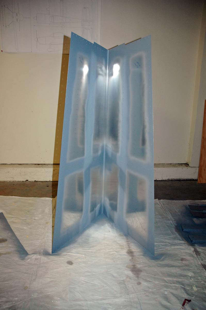
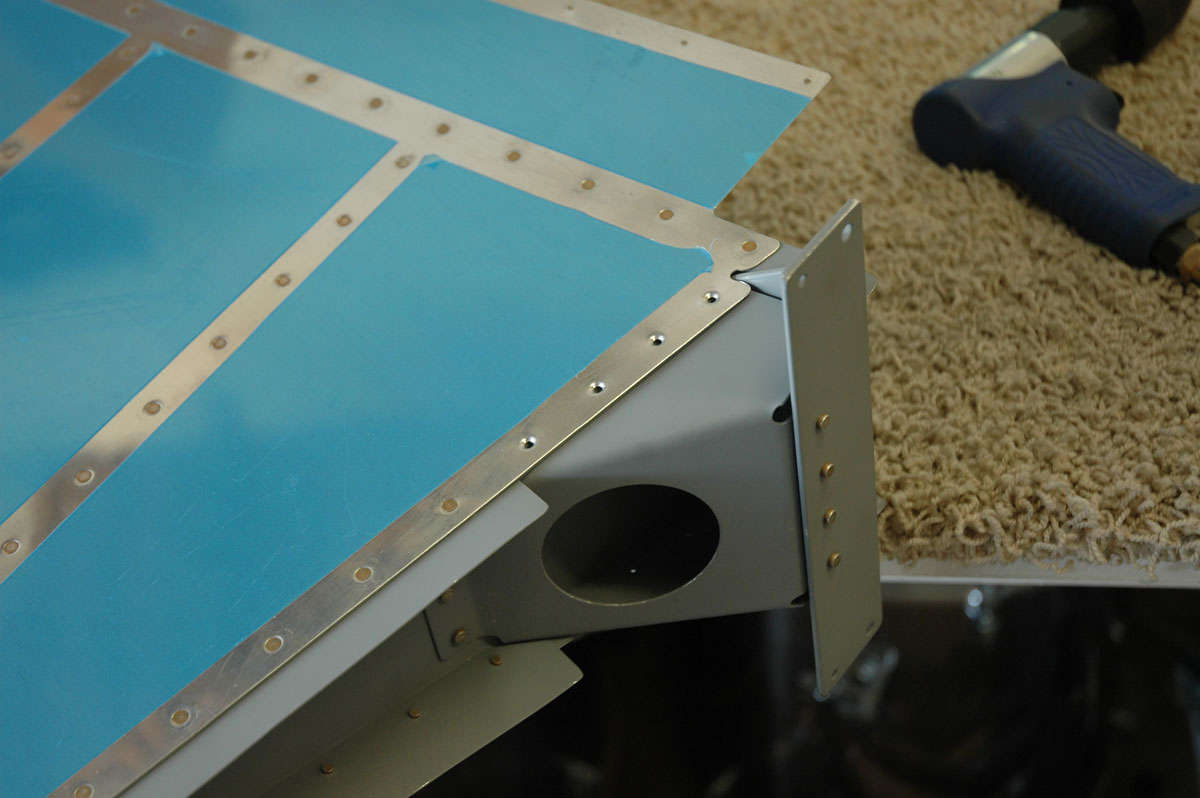
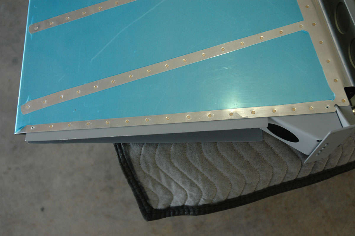
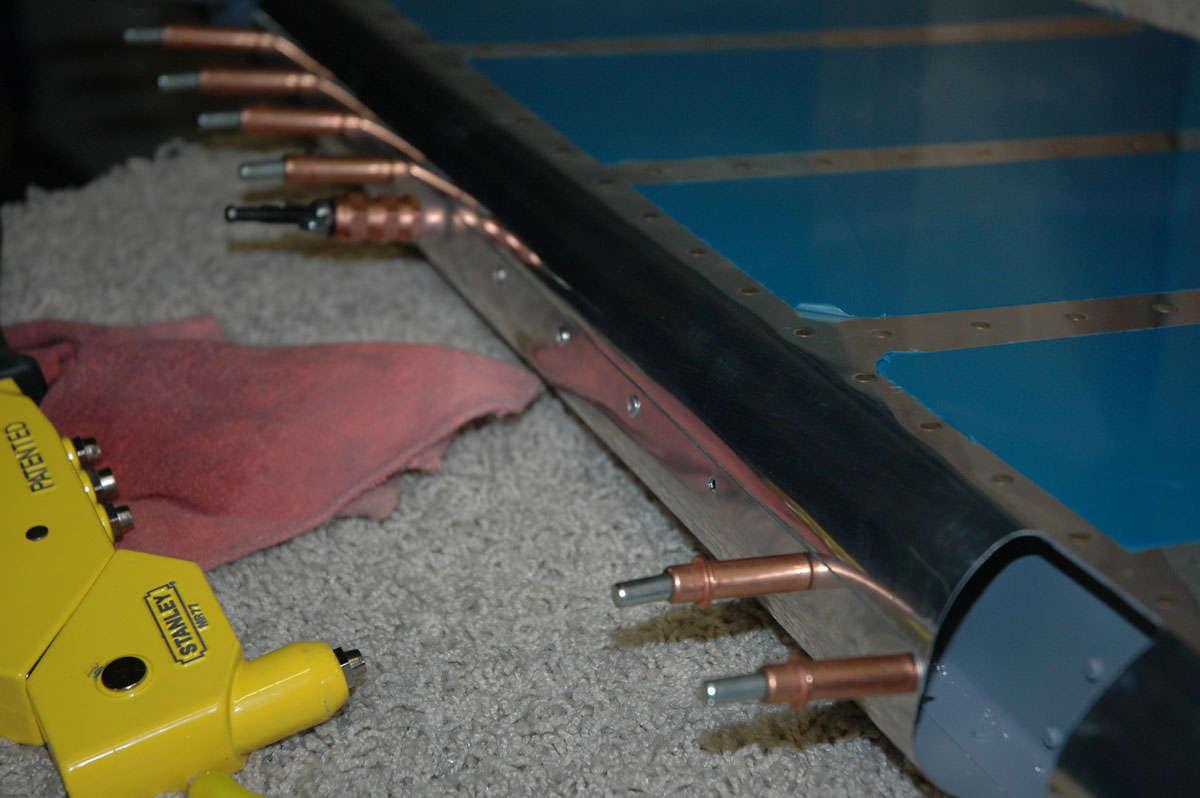
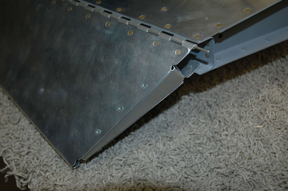
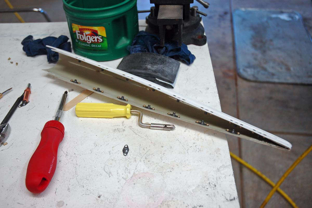
So tonight, Monday night, I finished riveting the rear spar into position and attaching the ribs to the spar. Ripped off the blue plastic protective film and here's the thing about done.
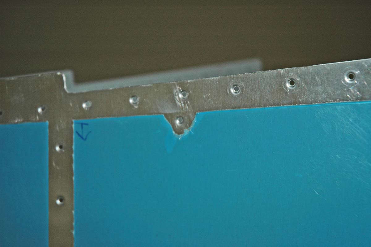
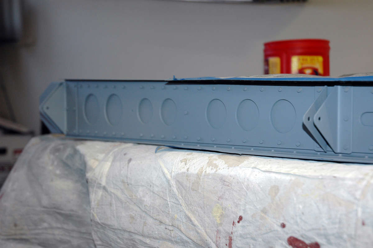
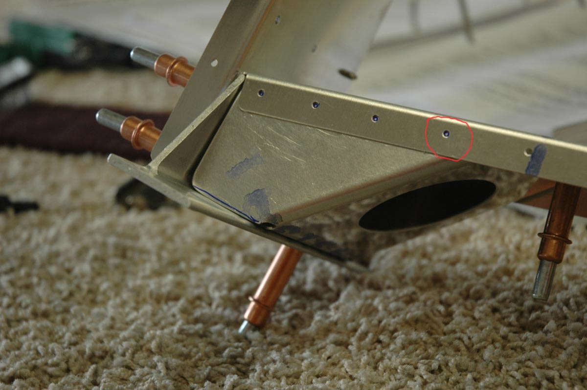
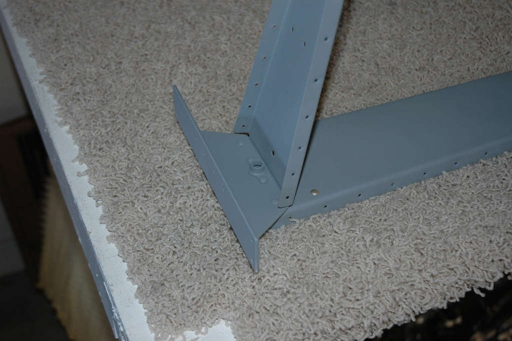
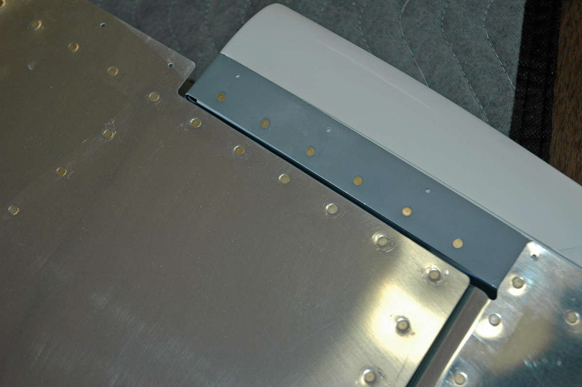
A closer look at where the two halves join...this will someday be the part that attaches to the aft fuselage. I need to do a bit of touch up priming and attach the center elevator hinge before I can say it is really done. The missing rivets on the interior edge are supposed to be there. A close reading of the plans tells me that an aerodynamic fairing will be attached at these holes during the final assembly.
Not 100% happy with my skill level on some of these little parts, but I guess that's part of the process. Next session I'll do the painting and finish it up, and then figure out a way to store this assembly for awhile. Then, on to the vertical stabilizer. Done with "HS" parts...now to "VS" parts.
March 29, 2009
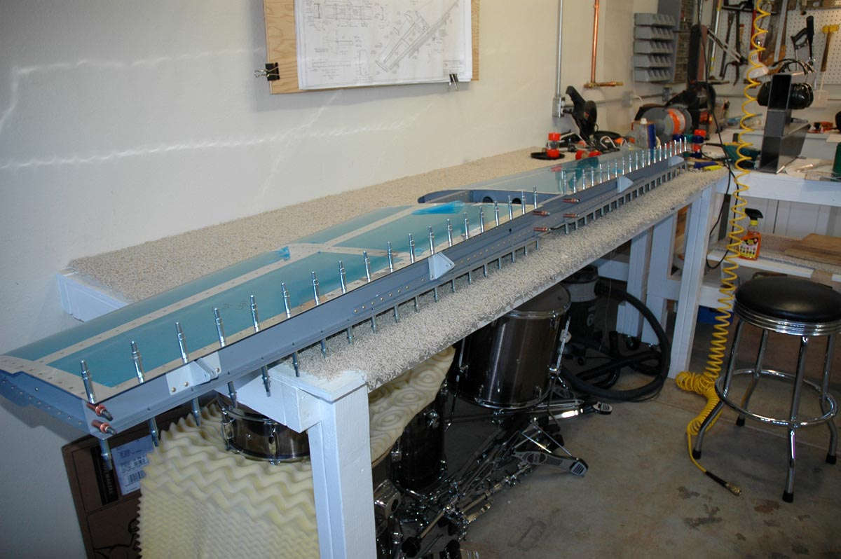
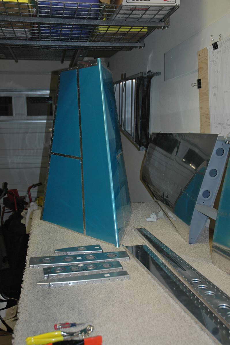
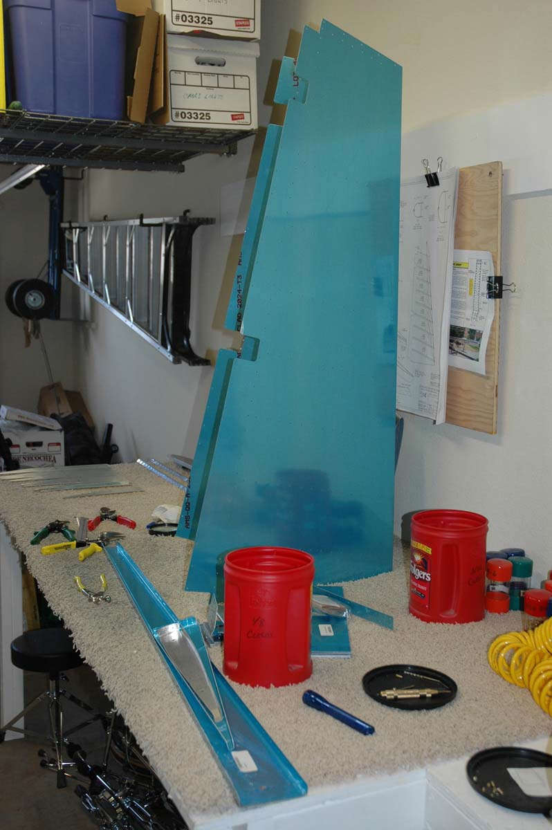
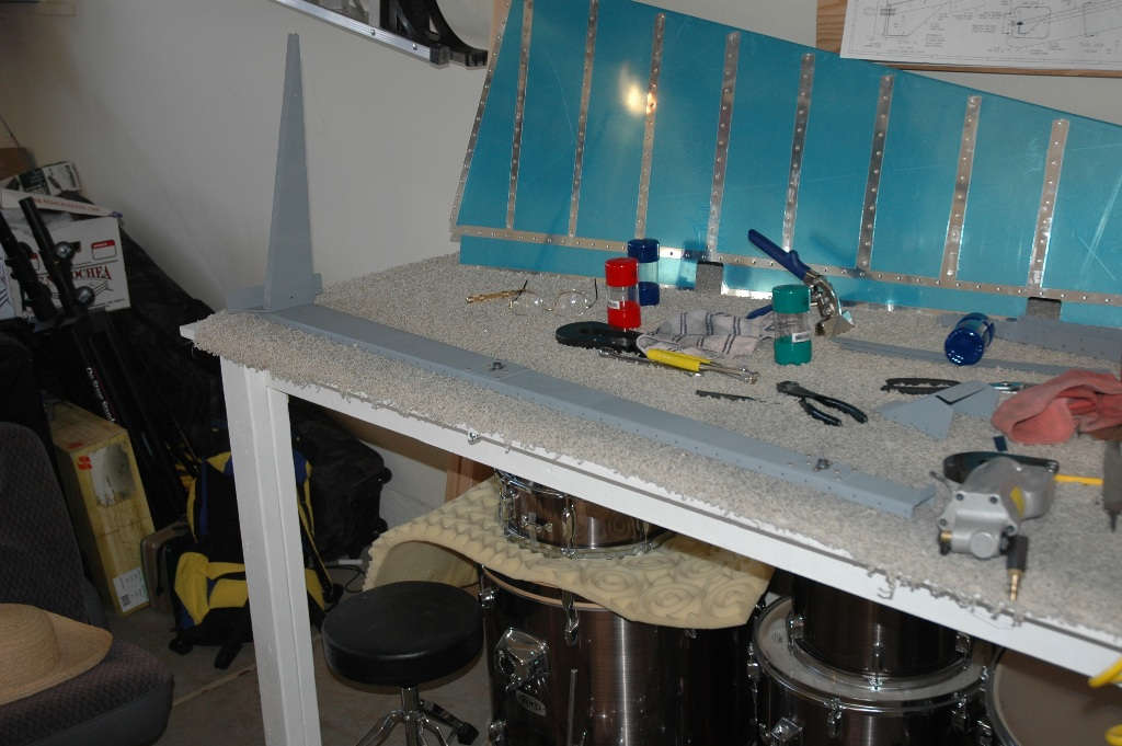
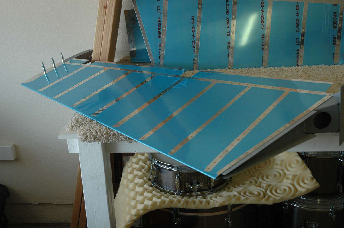
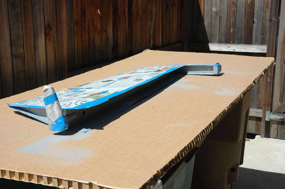
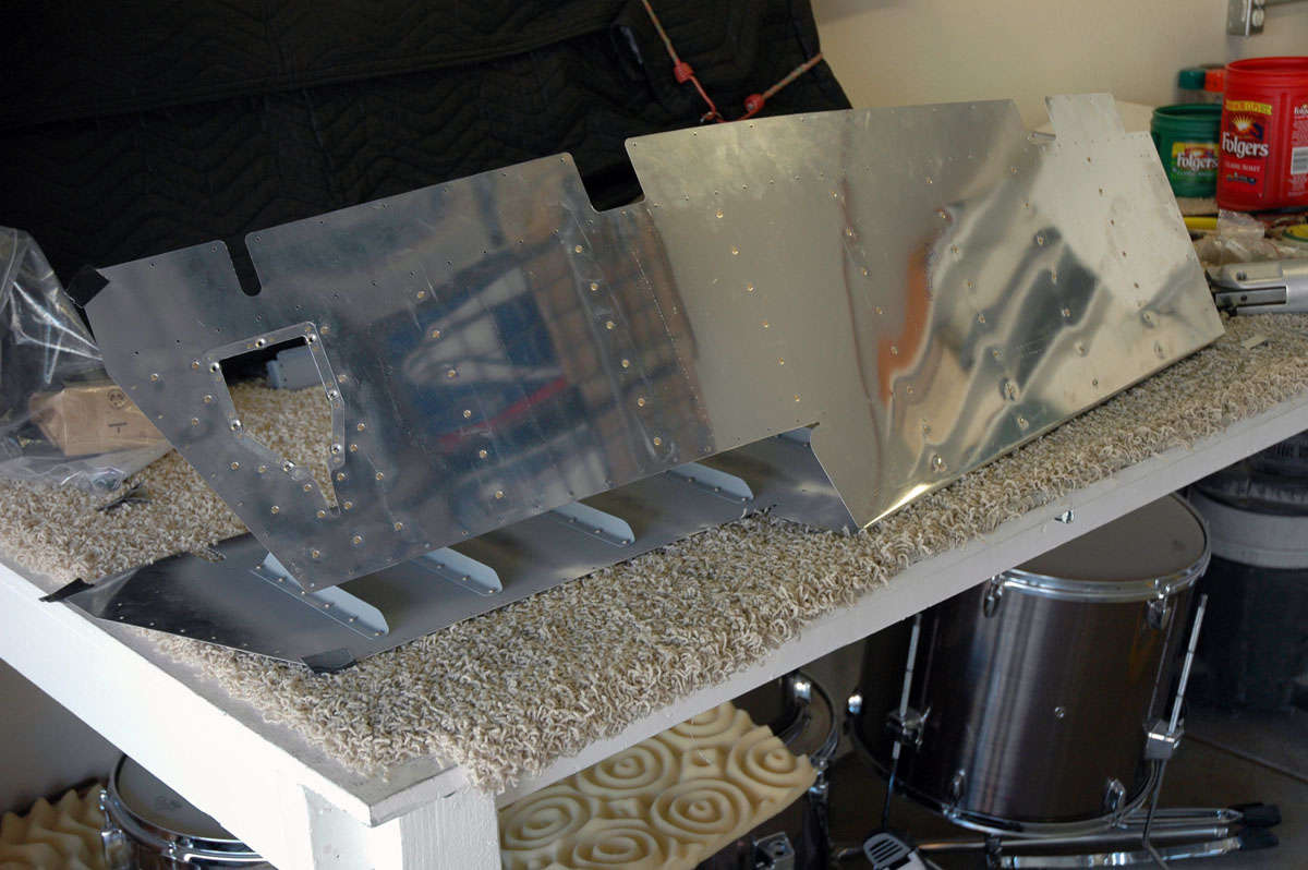
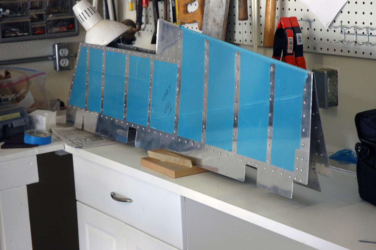
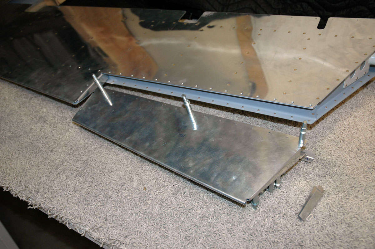
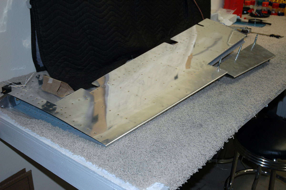
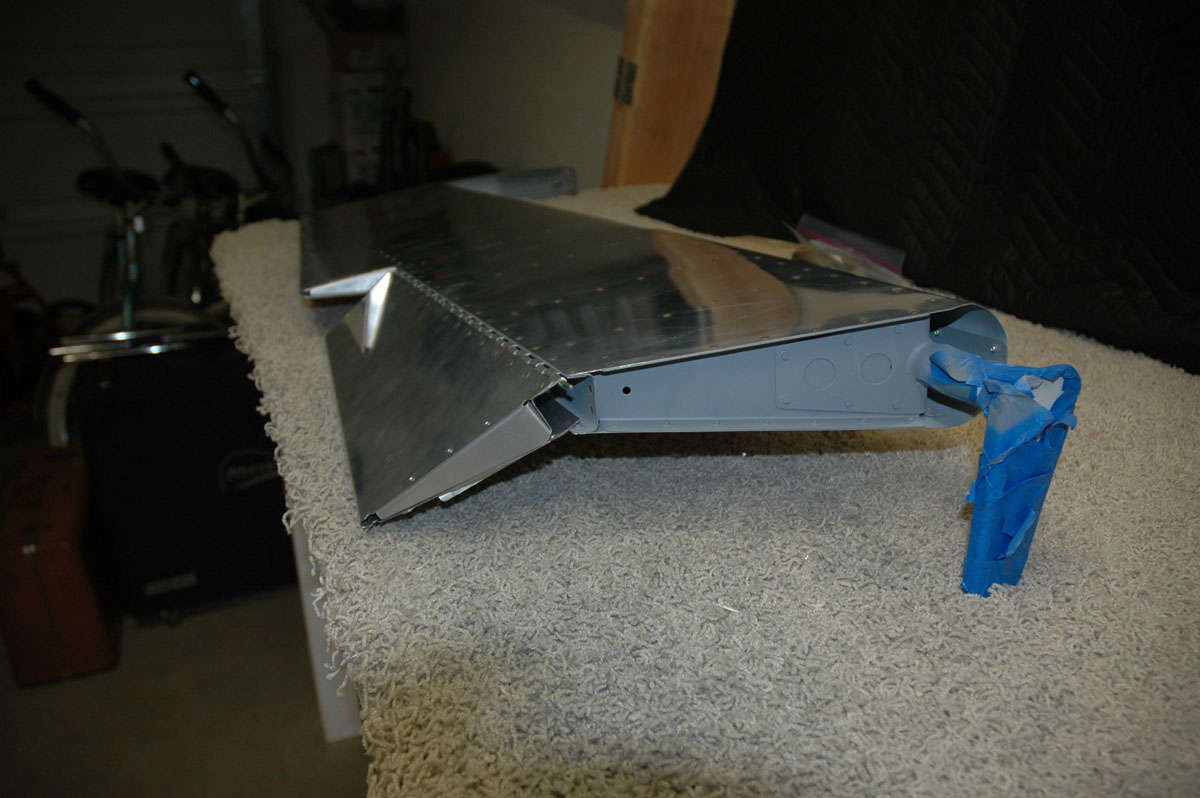
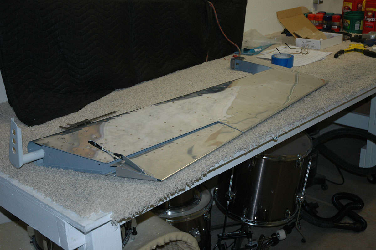
I'd like to say that I got a lot done this week. I did, but it had nothing to do with building an RV-8. I flew all week, took care of some other obligations, did some family stuff, and spent a bit of time re-organizing my work area. I also did some touch up painting to the primer on the horizontal stabilizer and pulled out the vertical stabilizer parts. Laid them out on the workbench. Looked at them for a bit. Looked at them for a bit more. Turned the light off and will be back next weekend to start playing with them. Get to fly again all this week. Here's a photo of the vertical stabilizer parts laid out, with the 99.9% completed horizontal stabilizer in the background. I'll need to carefully prep that part for storage after it is completely done.
We will see what we can get done next week.
April 5, 2009
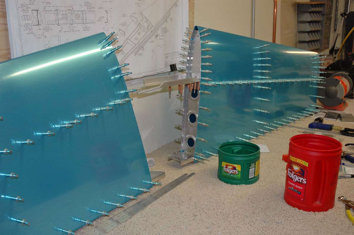
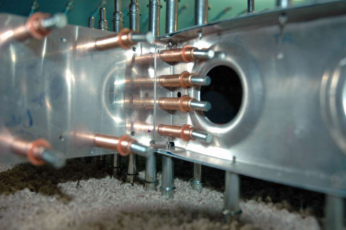
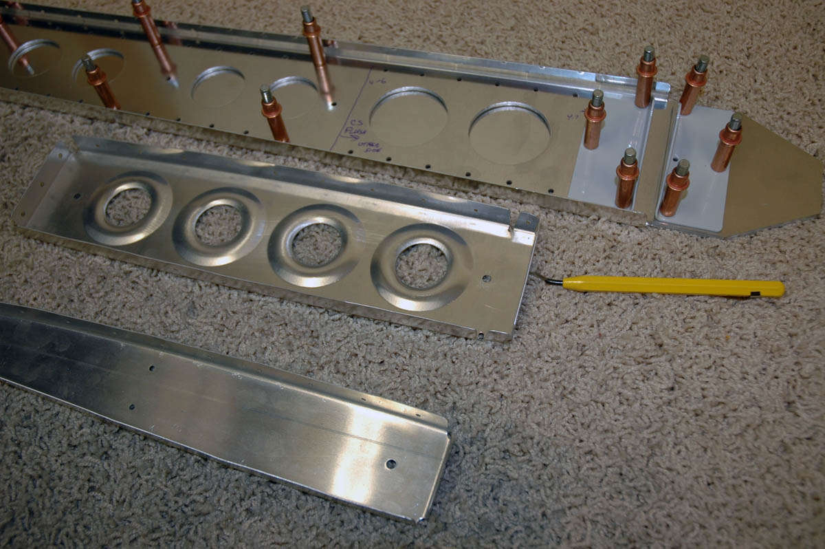
Dove into the vertical stabilizer this week, though it really was only Thursday night for a couple of hours and a couple of hours on Saturday. Many other things to keep me busy, so it was just enough time on the project to keep it interesting. Here is where I started...the vertical stabilizer is simpler than the horizontal, and only half as big. Here are the components laid out. The thicker piece of aluminum with the holes in it is spar doubler for the aft spar:
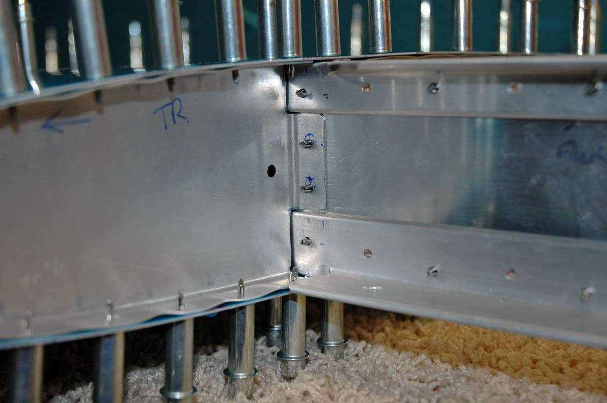
Here are some of the parts as I was doing some edge finishing and fluting. At the upper right, one of the hinge bracket sets is clecoed to the spar doubler and spar in preparation for match drilling.
Here is the basic framework clecoed together for match drilling...two spars, three ribs...should be fairly simple if one reads directions carefully...
And here is the one piece skin wrapping around the clecoed framework, again for match drilling.

And here it is all drilled out and ready to be taken apart for preparation work...dimpling, deburring, edge finishing, priming, and then put back together for good with rivets.
And another view....just because.
And then I realized I made a major mistake because I did not read the instructions as well as I thought I had. When I was countersinking the spar for some flat rivets called out in the plans, it occurred to me the spar material was a bit thin for countersinking. When I checked the plans I realized I should have dimpled this part and countersunk the holes on the spar doubler. What a way to end a session...with the first major screw-up. Bummer. I can't salvage the part...you can't put the metal back, or so I've been told. So, I call Van's tomorrow and order a new VS-803PP for the princely sum of $18.00 plus shipping, and then next weekend do the holes correctly and match drill this part back in with the others. Fine way to end the day, eh? So, here is how not to do it:
April 19, 2009
Okay, two weeks went by....went flying for a week and then had some family things going on. In the meantime, my replacement VS-803PP showed up, so I took some time this past week to re-match drill that part, and then correctly dimpled and countersunk the spar and the doubler piece. Now, I was back to where I was two weeks ago.
So, I then dimpled all the ribs and spars, and then dimpled the edge of the vertical stabilizer skin, that part I could get to with the pneumatic squeezer.
Here is the forward spar (with the doubler in place) and the aft spar dimpled and countersunk and edge-finished and deburred...almost ready to go.
Then I grabbed my oldest son, Adam, who helped me dimple the interior holes on the skin....having two people really helps when using the DRDT-2 dimpler (which I do have), or probably a C-frame (which I don't have) also. The second set of hands minimizes skin scratches as one hunts for the hole with the male part of the dimpler set. Those male parts will get you evey time.
Then, it was off to the paintshop (garage floor) to do a bit of rattle can priming.
I'll let the paint cure for five days, then hope to do some vertical stabilizer riveting...maybe even finish the thing, next weekend. Time will tell.
May 10, 2009
Well, things have a way of happening in a surprising manner. My wife's mother passed away very unexpectedly on April 20, the day after the last posting, and so our family did some traveling and spent a week or more in Southern California. Obviously, nothing done on the airplane for the better part of two weeks. I got back into a few times this past week, and the vertical stabilizer came together quickly once I was able to spend a few hours on it. I clecoed the framework together and started riveting. Most of it was done with the pneumatic squeezer, so it went pretty quickly.
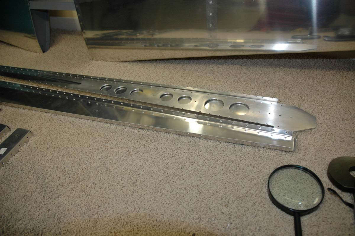
Here is the rear spar riveted together, with flush rivets used on the lower postion where it will later butt against the fuselage bulkhead.
And, here is the frame in the process of being riveted together. Didn't take too long to finalize the frame.
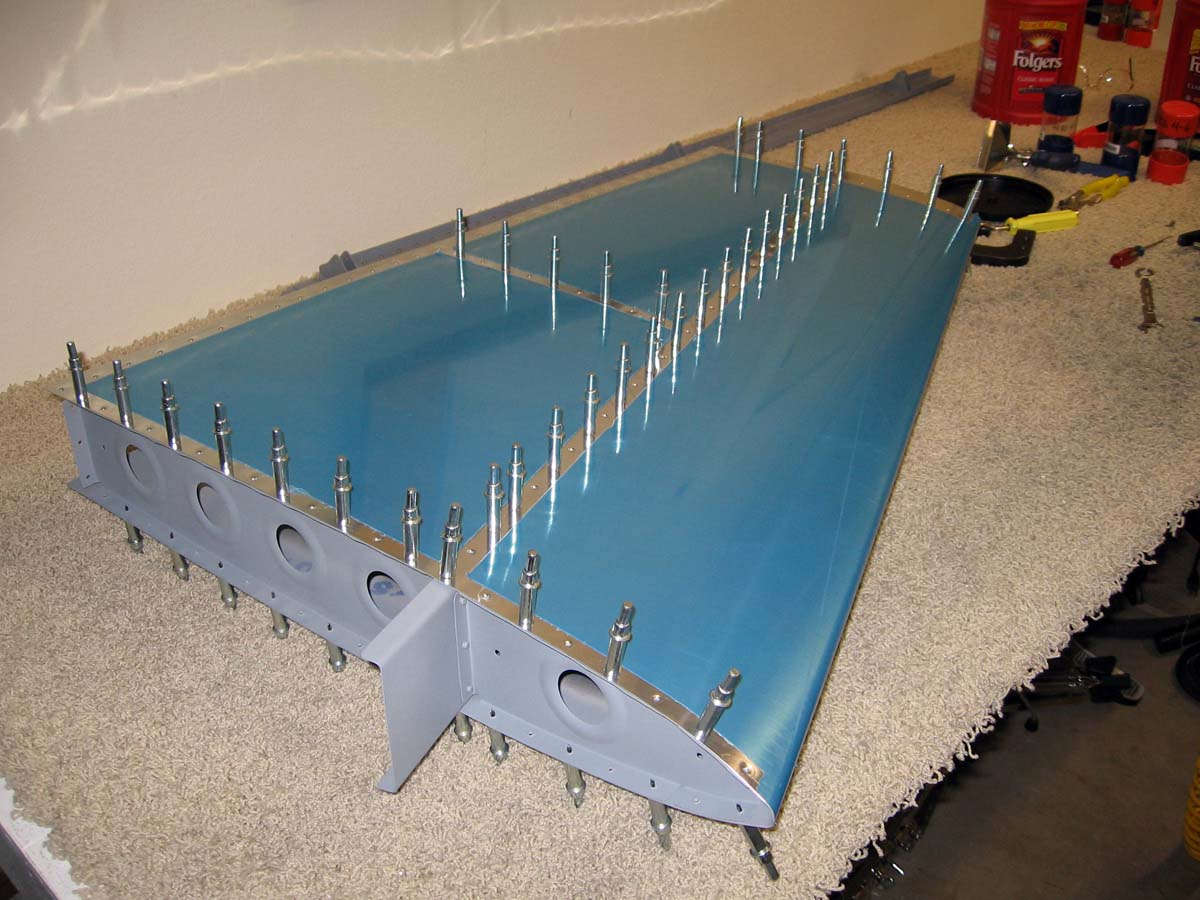
Once that was done, the skin is clecoed onto the framework, less the rear spar that is added once the interior skin riveting is completed. This allows access to get a bucking bar on the skin rivets that need the rivet gun to set them.
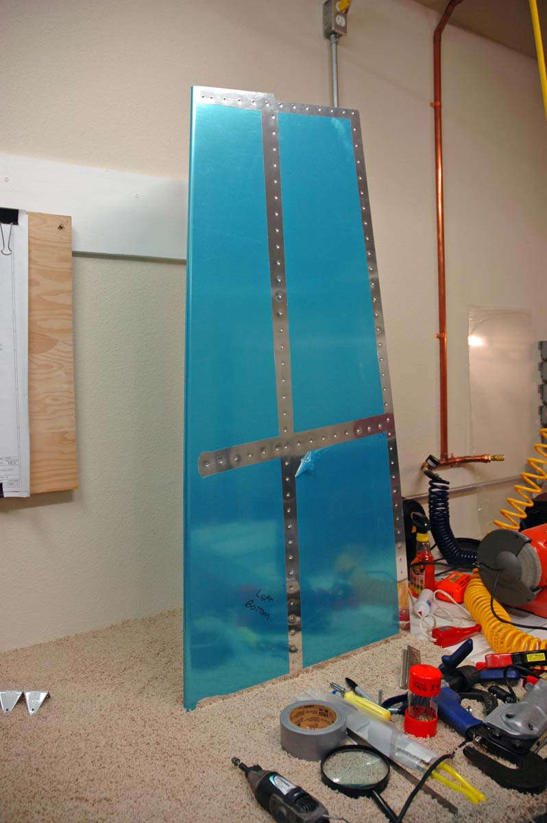
The flush rivets I set with the rivet gun went much better on the vertical stabilizer than they did on the horizontal. Part of the reason was dropping the pressure on the rivet gun, partly doing away with "protective" duct tape on the flush rivet set (didn't like that a bit), and partly because of experience gained. Once the interior skin rivets are done, the rear spar is attached, and the edge skin rivets can be done, this time with the pneumatic squeezer. Three pop rivets are used to attach the interior rib to the rear spar; all others are squeezed. Here is the vertical stabilizer about done, with me touching up the primer a bit.
And another view of me touching up the primer. After this was done, I added two coats of a gloss grey enamel to what will be the rear of the stabilizer where the rudder attaches. It will look better when done.
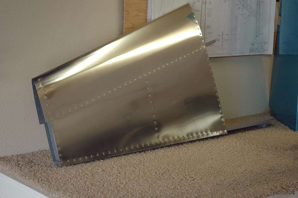
So, all that was left after that was to pull the blue protective plastic film off and clean it up a bit. Looks pretty good to me.
On to the the rudder, the first of five control surfaces to be built. But first, this coming week will get me reacquainted with a big rudder, that of the DC-3. Yep, I need to go do a bit of tail wheel brush-up, this of the DC-3 variety as I get to go play with that beast for bit. My employer has made that opportunity available to me, so I will do some flying with real piston engines, these of the 1,300 hp. variety.
Someone told me recently that you can tell when a DC-3 has flown over because everyone on the ground is covered with flecks of oil. Yep.
May 17, 2009
Well, I got to spend about two hours this week on my RV-8...not a good pace. Traveled for five days, so can't do much about that, then had to compress a week's worth of "things" into a Saturday morning. I did get to sit at my workbench for a bit on Friday night, looking at the rudder plans and the rudder parts on my bench. Then I did some work on Saturday and a bit on Sunday.
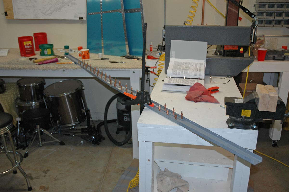
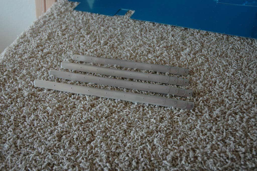
The first step is to fabricate rudder stiffeners that are riveted to the inside skin. There are fourteen of them, one for each side at seven points on the rudder, and each pair is a specified length. The stock used to fabricate these stiffeners is angle stock, pre-drilled with eventual rivet holes and markings for trimming. Each piece of stock produces two or three stiffeners. I carefully lined out the stiffeners from the stock, then began to trim them with aircraft shears, as per the directions. That didn't work out too well, at least my attempts at precision cutting didn't work out too well. The upshot is that I wrecked the first stiffener I was working on....it cracked near the end. I thought about trying to make it work, but decided in the end that I'd rather just replace it.
The learning curve soared after that mistake. I realized to just make rough cuts with the shears, then use my bench sander to make the final trimming. Worked much better. Each stiffener thus needs a rough cut with shears, a visit to the belt sander, then some filing, some edge finishing, some Scotchbrite wheeling, and then a bit of clean-up. It would probably be faster to do each step to all of them at once, but working through one from start to finish breaks up the monotony, and benefits the learning curve. But, I only got eight stiffeners done (nine if you count the one I wrecked, but I probably shouldn't count that one, eh?).
8 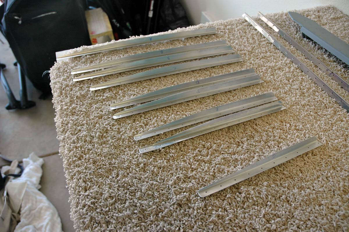
Oh well, it is progress, and I don't have a schedule. This week looks like it will be like last week, so hopefully I'll get back to work next Saturday.
May 25, 2009
Plugged away this weekend...probably got to spend four hours on Saturday and a few other hours here and there. Not making the kind of progress I had hoped for but that's the way it goes. Too many other things demand my time right now. What I did do was finish the stiffeners, replaced the bad one I did last week, did all the prep work as far as finishing, deburring, and dimpling. They are done now.
During the process, the stiffeners were clecoed to the rudder skin for the match drilling. The stiffeners are riveted to the skin, then the rudder framework is constructed and riveted into the rudder. Here's what the outside looks like:
And here's the inside with the stiffeners in place (at least one side):
Then, tonight, after I finished the stiffeners, I began to dimple the stiffener holes on the rudder skin. Slow process, and though I wanted to prime all these parts tonight it just wasn't going to happen.
Diversions occurred, but that is par for the course. I'd rather not rush things, so I'll go off and fly away tomorrow to Colorado to work for a few days, then back on Friday. I hope to make a bit more progress on Saturday. I also want to arrange for an EAA technical counselor to take a look at what I'm doing, so I'm also working on that. I've had some good mechanics look at the horizontal stabilizer so I'm on the right track. Time now, though, to start to cultivate a working relationship with someone who knows RVs pretty well.
June 14, 2009
It's been two busy weeks since I last updated. Last week I got a few things done but ended up too busy to post anything here, not that anyone is waiting to see what I've done. But for myself, it is helpful to keep the progress current, if only to mark where I have been. I continued to work, albeit slowly, on getting the stiffeners attached to the rudder skin. I was able to prime the stiffeners and the inside of the skin where the parts met. Used my customized spray booth again (garage floor). Did that before I went off and flew for a few days...gave it time to cure, etc.
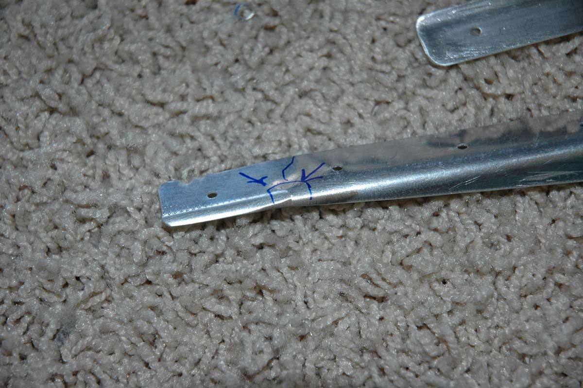
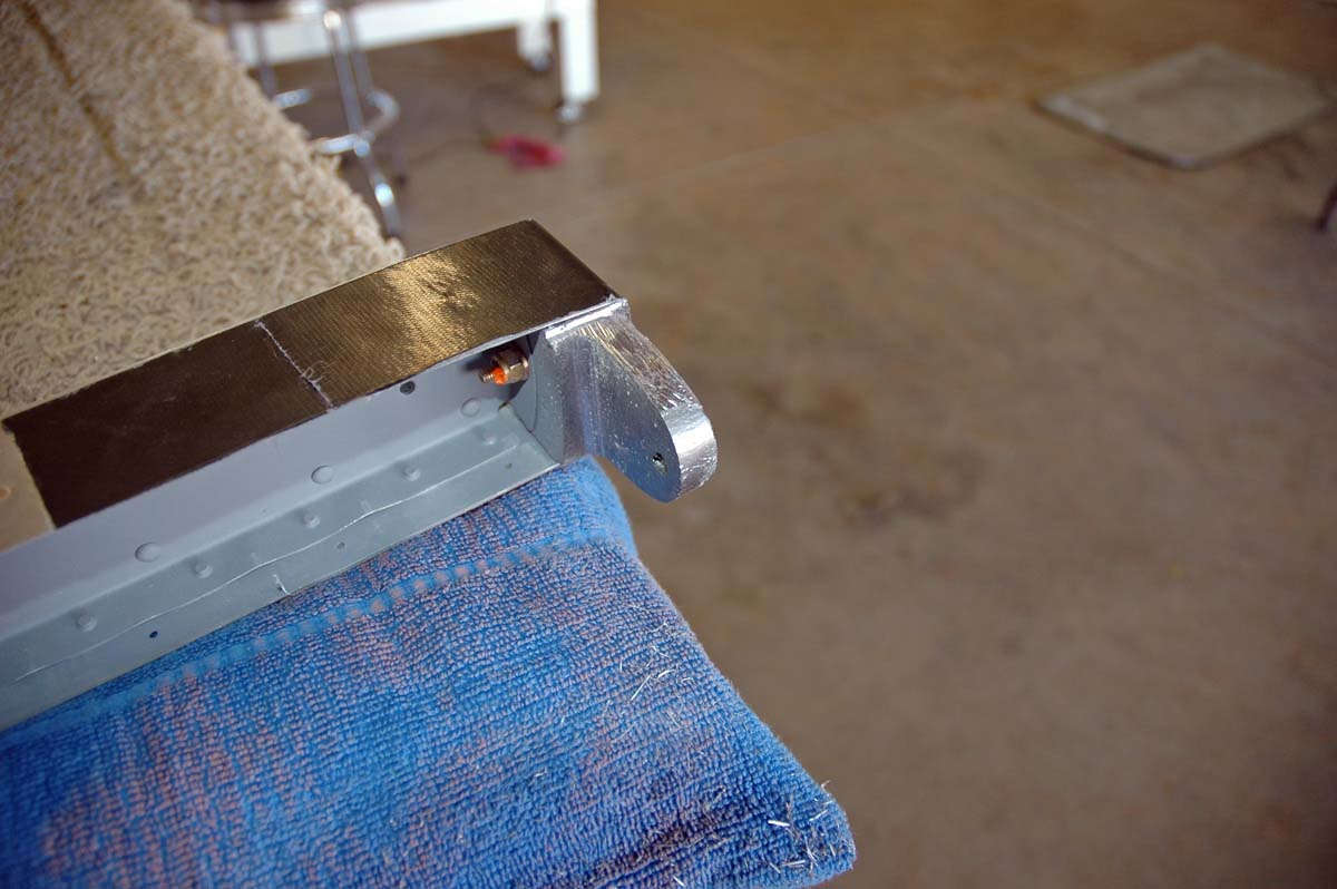
I also worked on some of the frame parts. This old R-710 part, officially known as the "rudder horn brace," has proven to be a problem for those that have gone before me, and I read with interest some of the problems to learn from prior efforts. The main thing is that if you just follow the directions a bunch of rivet holes end up too close to the edge of the part. So, I measure a few times and trimmed a few times and got close to what I wanted. Ah, the benefits of having other RV-8 and RV-7 web sites to pore over. It turned out well, but even so the edge distance is pretty tight. I'll try and post a photo of the edge distance problem later.
When you put the bottom part of the rudder frame together and cleco in the pesky R-710 part, here is what it looks like. The rudder horn is part sticking out the side, the part that will have the rudder control cables attached many years down the road. You can see here where there is potential edge distance issues with the row of rivets.
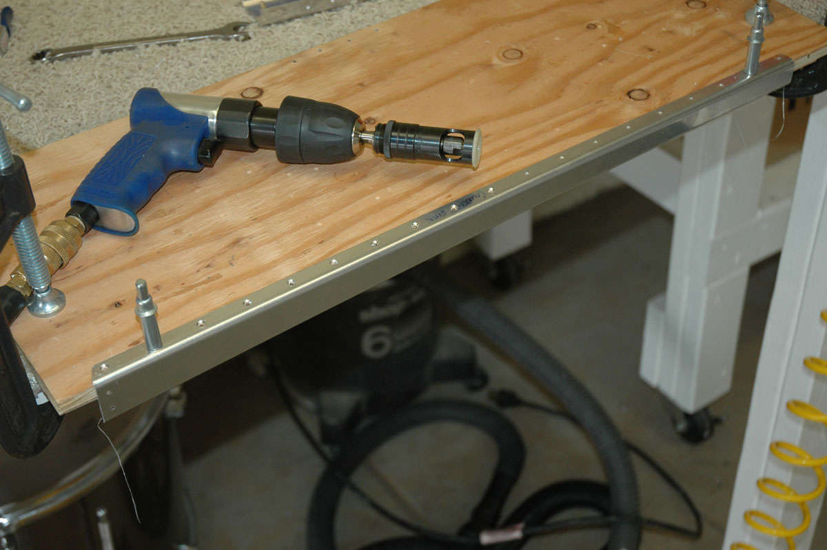
Last week, sometime around June 3rd, I was able to cleco the stiffeners into position and did some back riveting. Backriveting is actually fairly easy, as long as the parts are held flat and you can hit the shop head squarely with the special back rivet set. You lay the parts onto a heavy metal plate to provide the backing punch, then rivet straight down on the shop head.
Things went pretty quickly...too quickly I guess, as here is how some of the heads turned out.
Not sure how that happened, as I was very careful to align the tool with the rivet shank. Might have had too much air pressure on the gun. Might have had alignment problems keeping the skin pried open far enough to reach those rivets. Whatever. Bum-mer, as they say in the seventies.
So, that's how I left my rudder when I left on Thursday, June 4, to go to Manitowoc, Wisconsin, to play DC-3 for a week. More of that quality tailwheel time to make me a better RV-8 pilot, or so I tell myself. I suspect RV-8 is to DC-3 as mashed potatoes are to clutch discs. But delusion is okay as long as I think it's real.
Anyway, got back to the project this past weekend, spent maybe four hours on Saturday and another two today, Sunday. Here and there, around mowing lawns and taking care of stuff. And, saying hello to the family as I drop by for a visit, or so it seems. So I got to drill out quite a few rivets...getting good at that. Not too bad, actually. I have found if I center punch a point on the rivet, then drill a pilot hole, I can then use a drill bit a bit bigger and drill it square on the center of the rivet. That usually takes the factory head of the rivet off, then I can use a pair of dykes to pull the shop head out. Usually works; I'll shoot some pictures next time I do it which probably will be soon.
So, I got the bad rivets out and back riveted in some good ones. Not 100% good but meets my personal standard which is picky enough, or so I think. One can use special rivet tape to hold the rivets in place while they are inverted onto the back rivet plate, which is what the green tape strips are doing in this photo.
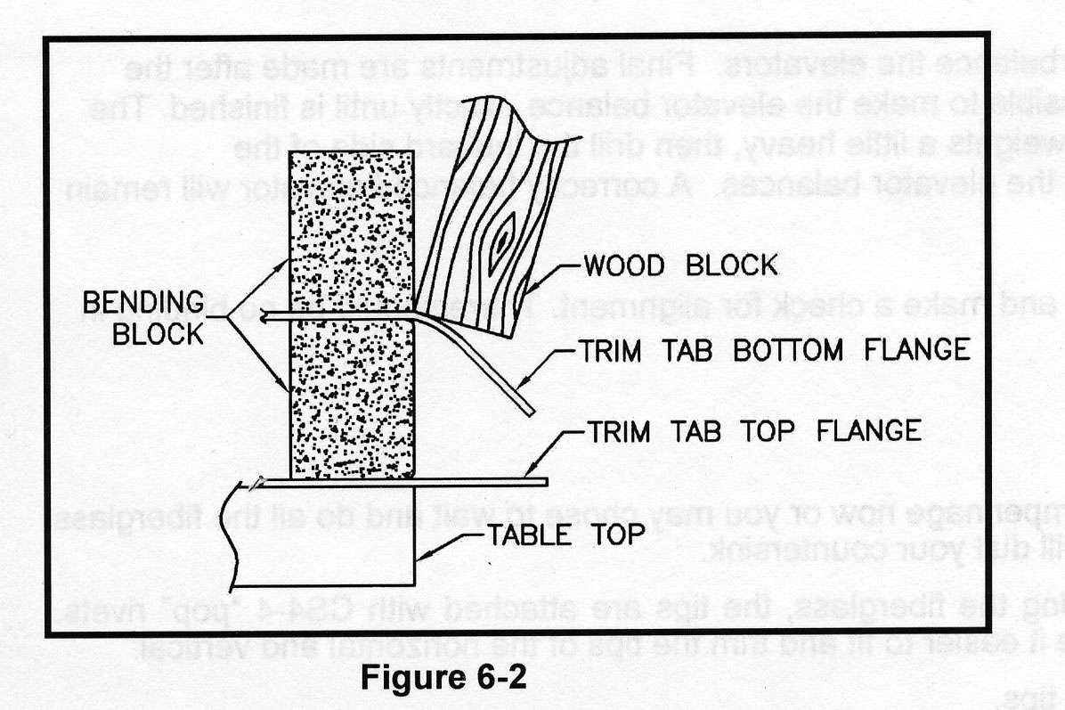
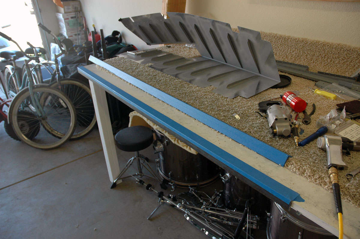
Then I had to rebend the trailing edge back to approximate the angle needed to fit around the rudder frame. Van's suggests a bending brake made of two 2 X 8s and some hinges. Built that...worked okay but not great. End result after tinkering a bit made the whole thing work out okay.
Then I did the match drilling on all the rudder frame parts, then clecoed on the rudder skin to the rudder frame. That's as far as I got today. Next up: match drill the skin to the frame, then take it all apart. deburr a lot of holes, dimple here, dimple there, edge finish, prime what needs to be primed, then start riveting this baby together. It's going to be awhile.
Also, I'd like an EAA technical counselor to look at these parts before I rivet them together. Get a second set of eyes, one's that know RV-8s and can give me some good advice. I've got a guy in mind; we shall see if he is of a like mind. That's it....
June 28, 2009
Another two weeks flew by just like that. Too much going on, but that included some family time as my youngest turned the ripe old age of 21 years. Okay, all three boys are over 21 now so I am completely done being a parent...finis...no more worries...more time to build airplane.....right. But the whole gang went to South Lake Tahoe last weekend for a good time but no airplane building. Then I flew last week...no airplane building. Just a bit here and there, then hit it pretty hard in the last two day. Got some stuff done.
In the period leading up to this weekend I did do the match drilling of the skin to the understructure. This included the parts I fabricated that will someday allow the fiberglass rudder bottom piece to mount to the rudder. It is clamped into position and then match drilled.
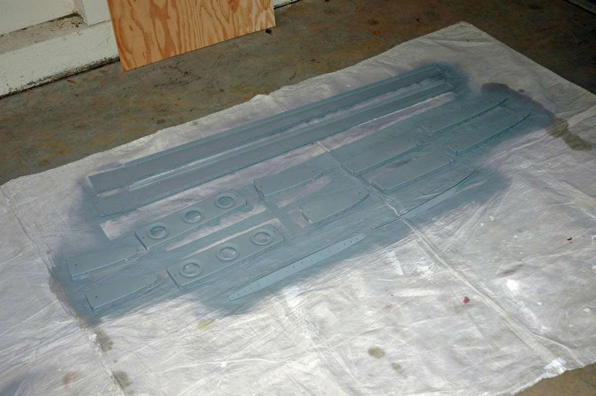
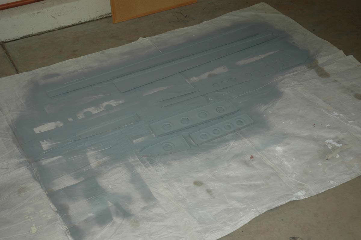
Then I did the finish work to the parts....deburred all the holes, edge finished all the edges, smoothed out all the stuff, dimpled all the skin holes and the matching parts on the understructure. That I pretty much did yesterday (Saturday) when it was, like 102 degrees in Lincoln and hotter yet in the workshop (garage). Not too bad but I did sweat a bit. Then, it was off to my spray booth (garage floor) for a coat of primer.
Today, Sunday afternoon, I clecoed the understructure back together and thought a bit, and double checked everything, then did some riveting. Screwed it up, naturally, and riveted the nutplate on the wrong side of the spar. This is the "before" picture, "before" I riveted it and then "before" I drilled out the rivets and "before" I did it again.
Okay, now we are making progress....here is the bottom part of the understructure completed.
So as the day started to wind down, I had to move on to some other things that demanded my time, but all the nutplates and spar doublers are properly riveted.
I just need to rivet the rudder horn reinforcer in and the understructure will be complete. Then the skin is fitted and riveted and more stuff is done and then the rudder is done. Next weekend. Fly again this week....Beech 300 King Air this time. No tailwheel.
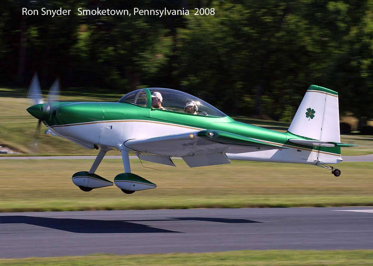
As a parting shot, I had requested photos a few months ago and Ron Snyder had sent me this one of him landing his RV-8 at Smoketown, Pennsylvania. I forgot to add it in so I'm adding it here as an inspiration. Cool photo, eh?
Until next week, then.
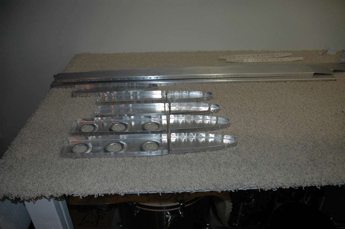
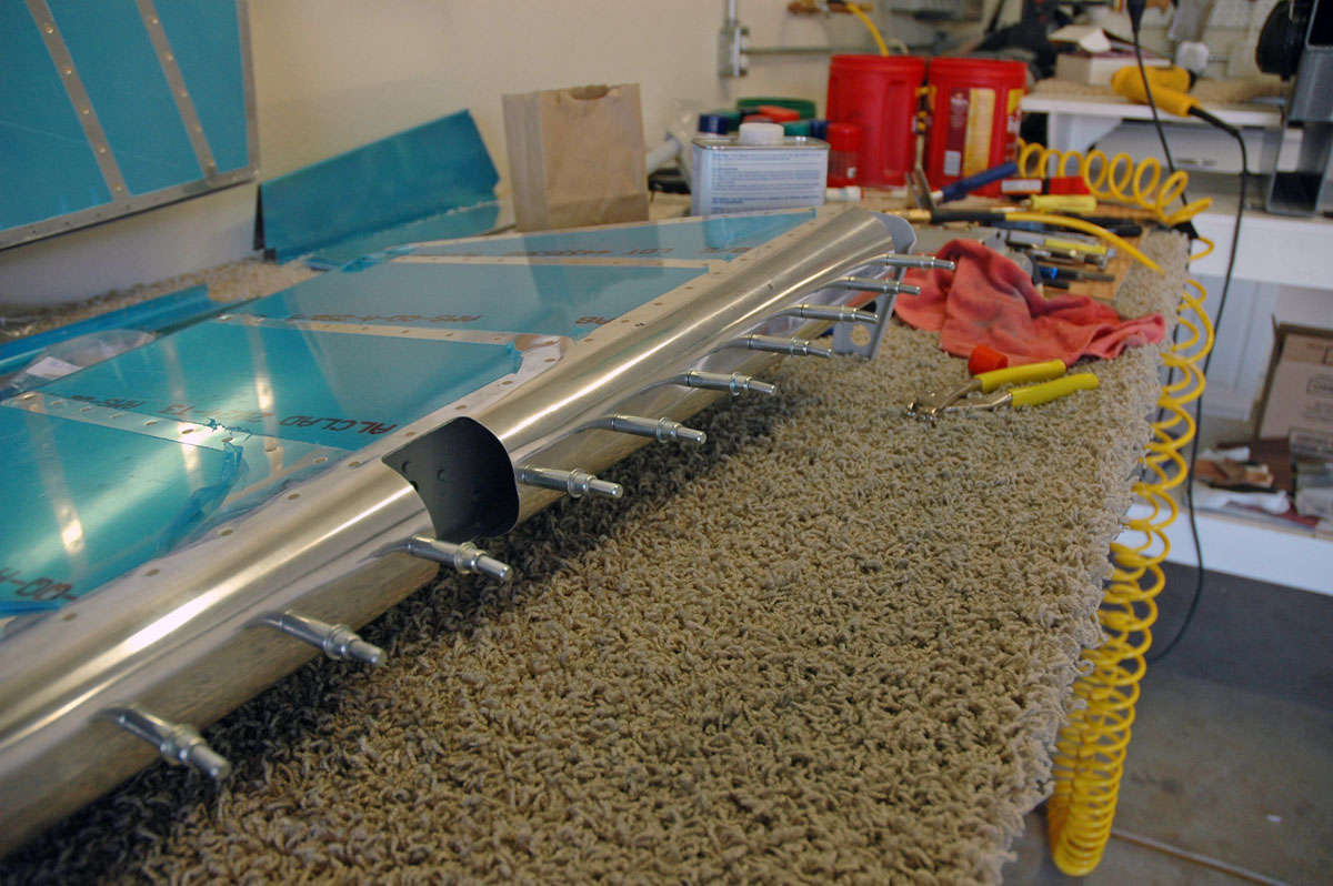
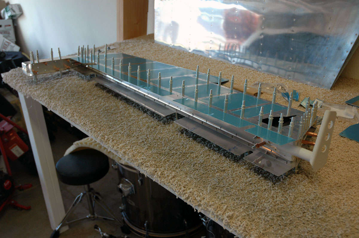
I last updated a few weeks ago...time flies by. In that period I arranged to have an EAA Tech Counselor come and look at my work up to this point. As part of that process, I decided to leave the rudder skin and rudder understructure as they were so the Tech Counselor could look at the disassembled parts. It's hard to inspect something once it is riveted together. So, I decided to set the rudder assembly aside and dive into the elevators. I pulled all the parts down out of the boxes and set them on the workbench, then began poring over the plans and instructions. I had not yet really looked the elevators beyond a cursory look to this point. In actuality, each elevator is like a rudder on its side, except the left elevator has a trim tab, and there are some other complications. However, the construction process starts like the rudder did: fabricate stiffeners from aluminum alloy angle stock, pre-punched, sort of, with where the trim cuts are to be made. There are, like, 28 elevator stiffeners, so it is bit more labor intensive to cut three or four stiffeners out of each piece of raw stock, trimming each one down close to where it needs to end up. Then, using my belt sander, I sanded each one down to fit the plans, then smoothed the edges and used the Scotch-Brite wheel to finish them off. Here is a completed stack:
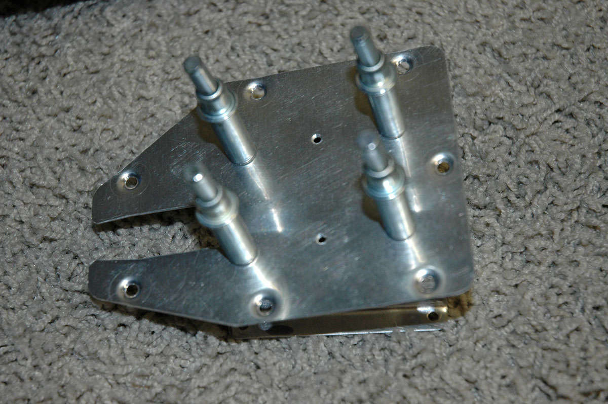
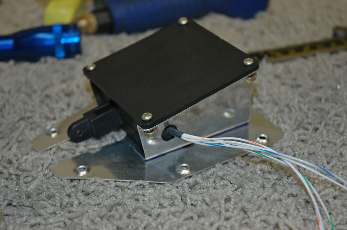
Here are the stiffeners on the work bench with most of the other elevator parts, waiting my loving attention. The box on the lower right is the electric trim actuator, an option for the airplane that I thought I should have. It is worked into the elevators during construction.
And here's another view after I trimmed the blue vinyl covering off the future rivet lines. The panel on the left side of the closest elevator skin is the panel into which the trim actuator will eventually be mounted. It is the lower surface of the left elevator. The trim tab will mount immediately aft.
Meanwhile, in the middle of all of this, the EAA Tech Counselor came by. Well, actually I went to the Lincoln Airport and picked him up on Saturday morning. He and another RV expert came by to look at my work. They both had a few helpful pointers and suggestions, but pronounced my work as sound and acceptable. One thing both mentioned is that I need to bend the rudder skin a bit better to the final fit, something I had already decided needed to be done. Something about tension on the skin and cracks at the trailing edge of the rudder. So, one of the gentlemen offered his custom set up to bend both the rudder and both elevator skins to exactly where they need to be. I'll go to his shop in a few weeks and do all three skins 'just right. I'd mention both their names but I haven't asked them permission, so I won't mention their names. Maybe next time. EAA is an invaluable resource for me and other builders like me.
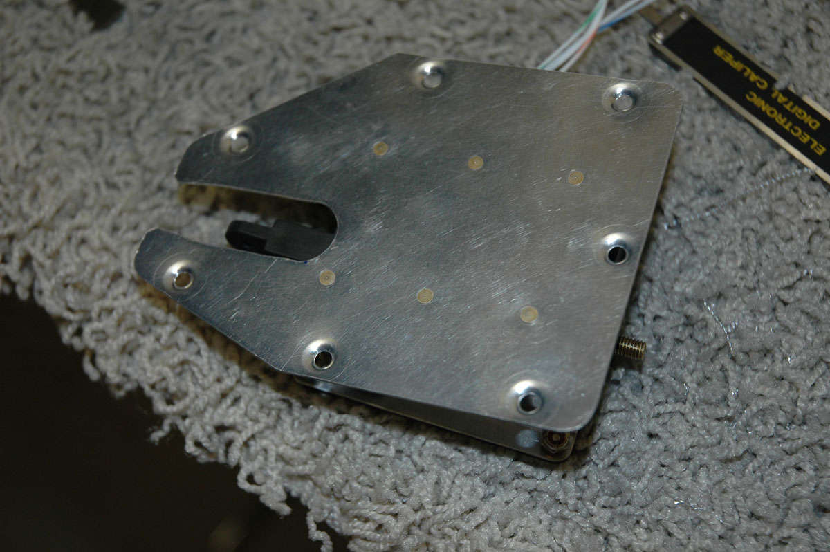
So, back to the elevators. Here is a closer view of the trim access area. A large backing plate is mounted under the skin and is fitted with nut plates. Then, a skin cover is screwed onto the backing plate as a cover, allowing access for maintenance later.
Stiffeners done, they are clecoed to the skins and match drilled. Twenty-eight stiffeners, six to nine holes per stiffener...you get the idea. But I enjoyed the drilling now because all the holes in the skin and stiffeners would have to be deburred next.
After all the holes are deburred, the skin and the stiffeners are dimpled for the later flush riveting. Here is my DRDT-2 making quick work of dimpling a stiffener. Right tools for the job....so much easier.
Then the skin was dimpled, mostly with the DRDT-2 but I had some problems on the rudder at the closest hole to the trailing edge, at the tight bend point. So, on the elevators I got smarter and used the Pop Rivet Dimple Die set which, amazingly, worked just fine in the tight places. Right tools for the job....so much easier.
That was all done on Saturday, July 11, for the most part. Then, today, Sunday, it was off to the paint booth (garage floor) for some primer. Inside the skins where the stiffeners will go, and on the mating surface with the stiffeners, and a bit on the rest of the stiffeners just for good measure.
Then it was put it all away for a week, or maybe more. I fly this week through Thursday, then two days home before jetting off to Dallas for a week of BE300 Simulator. Might get a few hours in next Friday or Saturday, but that's doubtful. The next step is to back rivet the stiffeners to the elevator skins. Then, on to the elevator understructure.
August 3, 2009
Busy couple of weeks and no time, or little time, to do anything on this project. Spent a week in Dallas doing simulator and checkride, then flew last week around the west. Back on Thursday and got to get a little time on Saturday and today (Monday) working on the elevators. One thing I did do just before I went to Dallas was screw up the lower right elevator skin a bit. I don't even know how I did it, but I was back riveting and must have come off the back rivet plate a bit. Anyways, I put a deep gash into the skin near the trailing edge of the bottom right elevator. Only about 1/2 inch long, but deep and ugly. Not a crack, but I worried it might become one someday.
I spoke with "my" people. That included an email off to Van's and I showed the skin to my A&P buddies. Okay, they all said. Ugly but okay. Okay then, press on and not replace the whole skin. I'd like to say it won't happen again but that's probably not true.
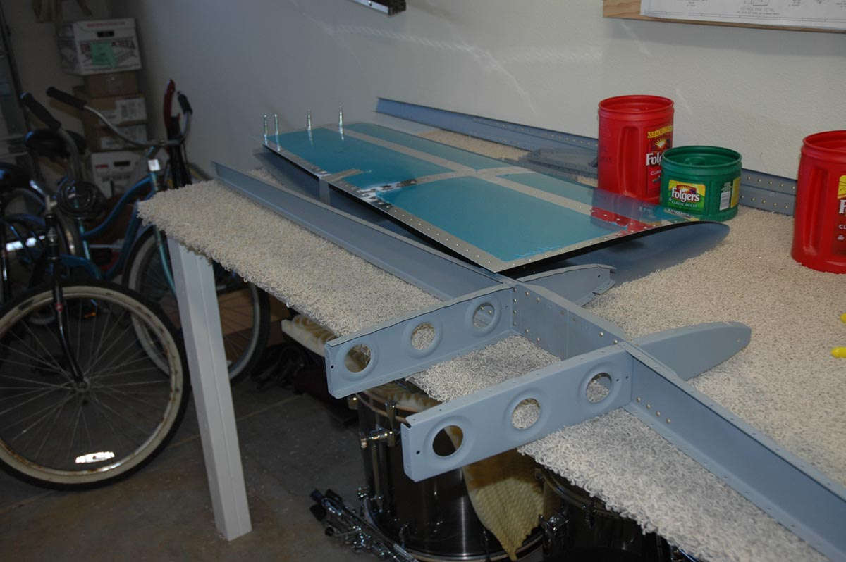
So, what I've done up to this point is finish the left elevator stiffeners (riveted into place) and about done with the right one. I assembled the right elevator substructure and worked out the counterweight frame that goes on the elevator tip forward of th hinge line. Here is the right elevator with the understructure in place.
And a look from the other end.
And here is the counterweight framework clecoed together.
Not too exciting, but I'm back in to it. Hope to get a few things done this week on the rudder and elevators. We shall see.
August 14, 2009
Two weeks went by and I made some progress. Felt a bit disjointed through it all but I did make some progress on both the elevators and the rudder. A big step was when I took Keith Peterson up on his offer to help me correctly bend the rudder and elevators skins. During my EAA Tech inspection held last month, Keith came along for the ride and noted that my rudder skin was not been far enough, then made the generous offer to show me how to bend them. Week before last I threw the skins into the Voyager and drove up to his house/shop/hangar at Nevada County Airport at Grass Valley. Took about an hour to do a nice job using some big angle iron and some clamps. Now I know how to do it. The wooden bending brake wasn't working out too well for me, so now they are done correctly. Bent the trim tab also, just for good measure. I wish I had some photos of that process but, alas, I don't.
I spent most of the succeeding days working on the rudder, but did get a bit of time to fit the left elevator skin to the understructure.
I also fit the elevator control horn into where it will mount and noted on other sites how you need to make sure all the holes align before drilling. Mine don't align so well, so I shall take a bit of time to make sure they do before I drill anything. I also read on another site that if one uses a #41 drill bit for holes that will be dimpled, the rivets will be tighter before setting them. The act of dimpling enlarges the hole just a bit, so if you start with a bit smaller hole (#41) it works out better. Sounds good to me, so I ordered some #41 drills. After I got them, I used some scrap and tried both #40 and #41 with dimples. Does seem to set better with the #41 so I shall do the match drilling on the left elevator with #41s and see how it all works out.
August 15, 2009
I had set the rudder aside in July to await the bending of the the rudder and elevator skins, and during the wait time I dove into the elevators. I was finally able to take Keith Peterson up on his offer to help me correctly bend the rudder and elevators skins. During my EAA Tech inspection held last month, Keith came along for the ride and noted that my rudder skin was not bent far enough, then made the generous offer to show me how to bend them. Week before last I threw the skins into the Voyager and drove up to his house/shop/hangar at Nevada County Airport at Grass Valley. Took about an hour to do a nice job using some big angle iron and some clamps. Now I know how to do it. The wooden bending brake wasn't working out too well for me, so now they are done correctly. Bent the trim tab also, just for good measure. I wish I had some photos of that process but, alas, I don't.
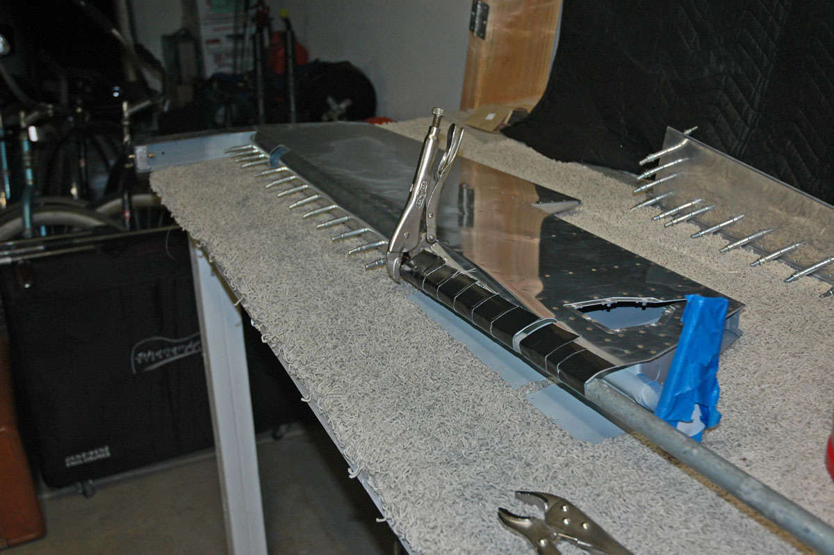
So, I got the skins back to my shop and set aside the elevators and went back to finish up the rudder. The skin had already been prepped so it was just a matter of sliding the skin over the completed understructure. It fit like a glove so I cleoced it all together and started to rivet it up. Followed the directions, of course (see later).
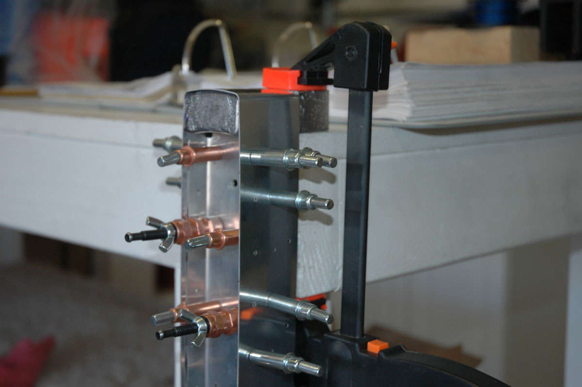
All the rivets at this point are squeezed. These four rivets I thought might be a problem.
But, using the longeron yoke, I was able to easily squeeze three of them. The fourth one, the one closest to the spar, proved to be a bugger because the nut plate for the bottom rudder hinge gets in the way. The plans say you can either use a squeezed or a pulled rivet for these four. I read some other sites and some comments about this rivet and decided to wimp out and pull a rivet both here and at the other end where things are pretty tight to get any kind of squeezed rivet in.
So, here is the rudder with the skin just about on.
I mentioned earlier about following the directions, and I really did follow them. After I got a dozen or so rivets on the skin done I was looking at the plans and saw that the callout for the rivets holding the top rib to the spar were squeezed. This surprised me a bit because there is no access once the skin is on. I had figured they would be pulled rivets like on the middle rivets on the horizontal stabilizer but, no, they were supposed to be squeezed. Bummer.
I scratched my head a bit and re-read the directions. No where in there does it ever say to rivet that rib to the spar. I consulted with "my people" and decided two Cherry Max rivets would work just fine there. Better than trying to drill out a dozen or more rivets. And it did work out just fine.
Then, we got into rolling the leading edge of the rudder. Followed the directions (again) and it worked out pretty well. Got my pipe, got my Gorilla Tape, got my son helping. Rolled that baby up. It wasn't as neat and/or clean as I had hoped, and it seemed like it would not go together well for the last half inch.
Did some more research on line. Determined that a bit of shear pressure on the seam would not be a problem so I started popping rivets.
Turned out okay, I guess. Not perfect, but pretty good. Seemed like more bending near the edge of the rib that I cared for but I don't see how else it could be done.
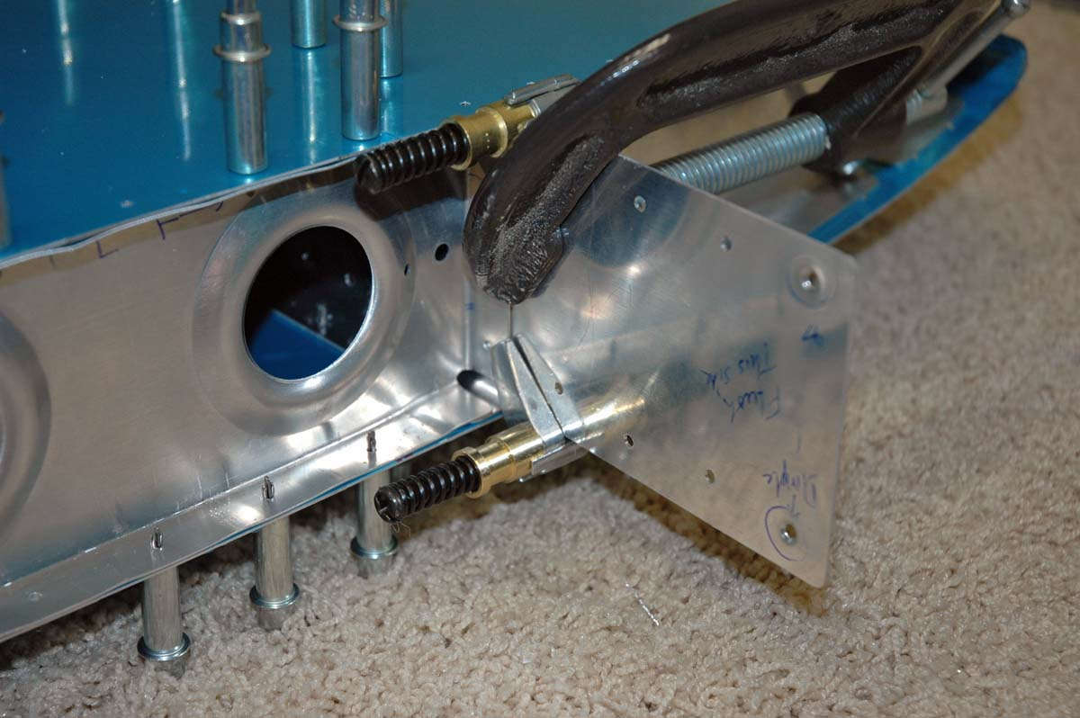
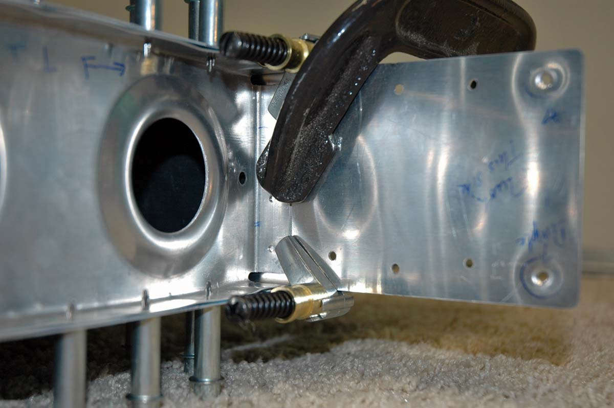
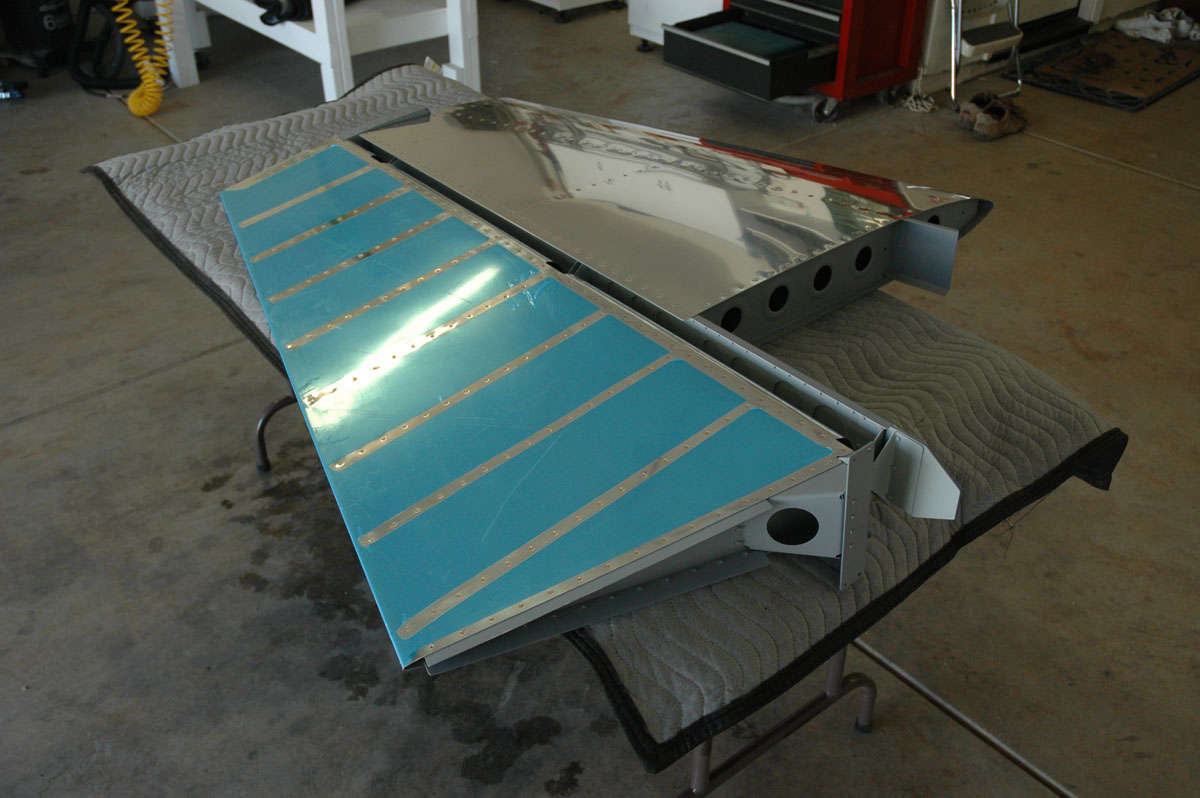
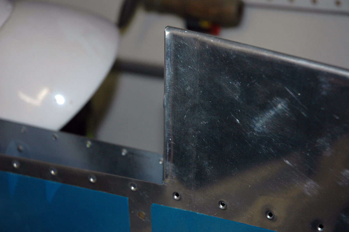
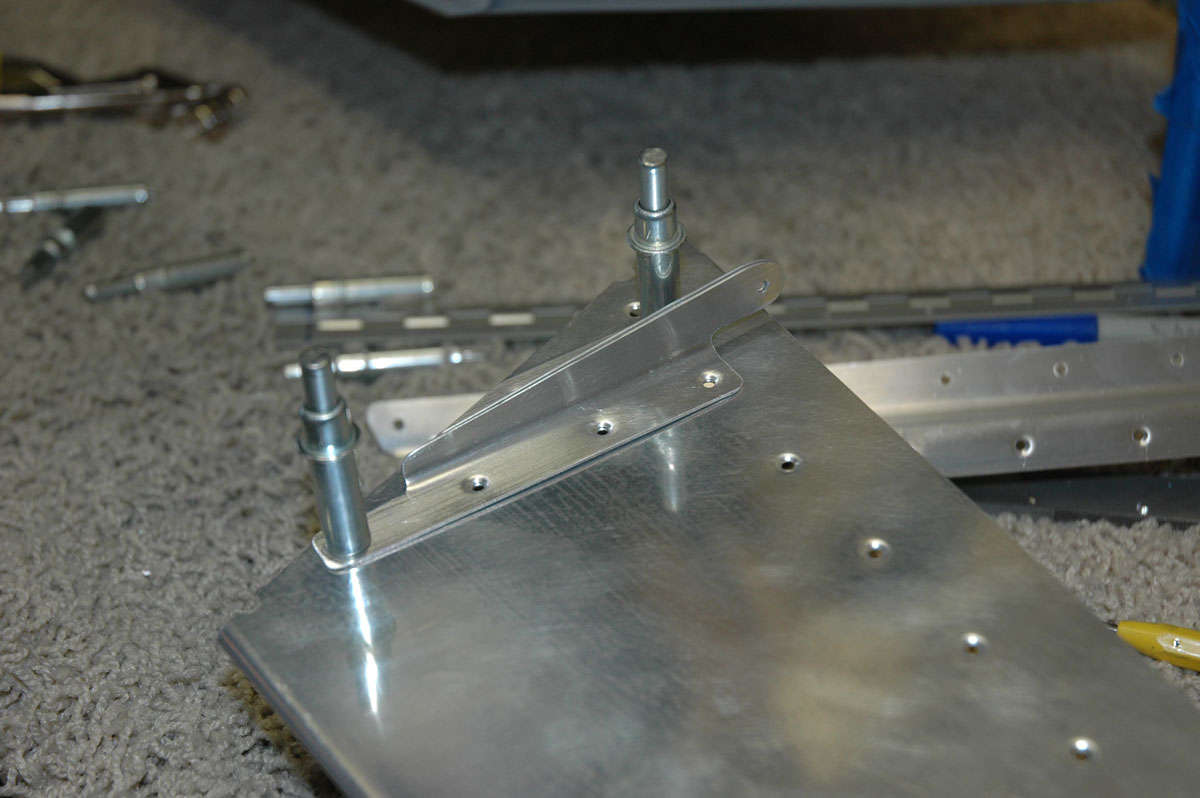
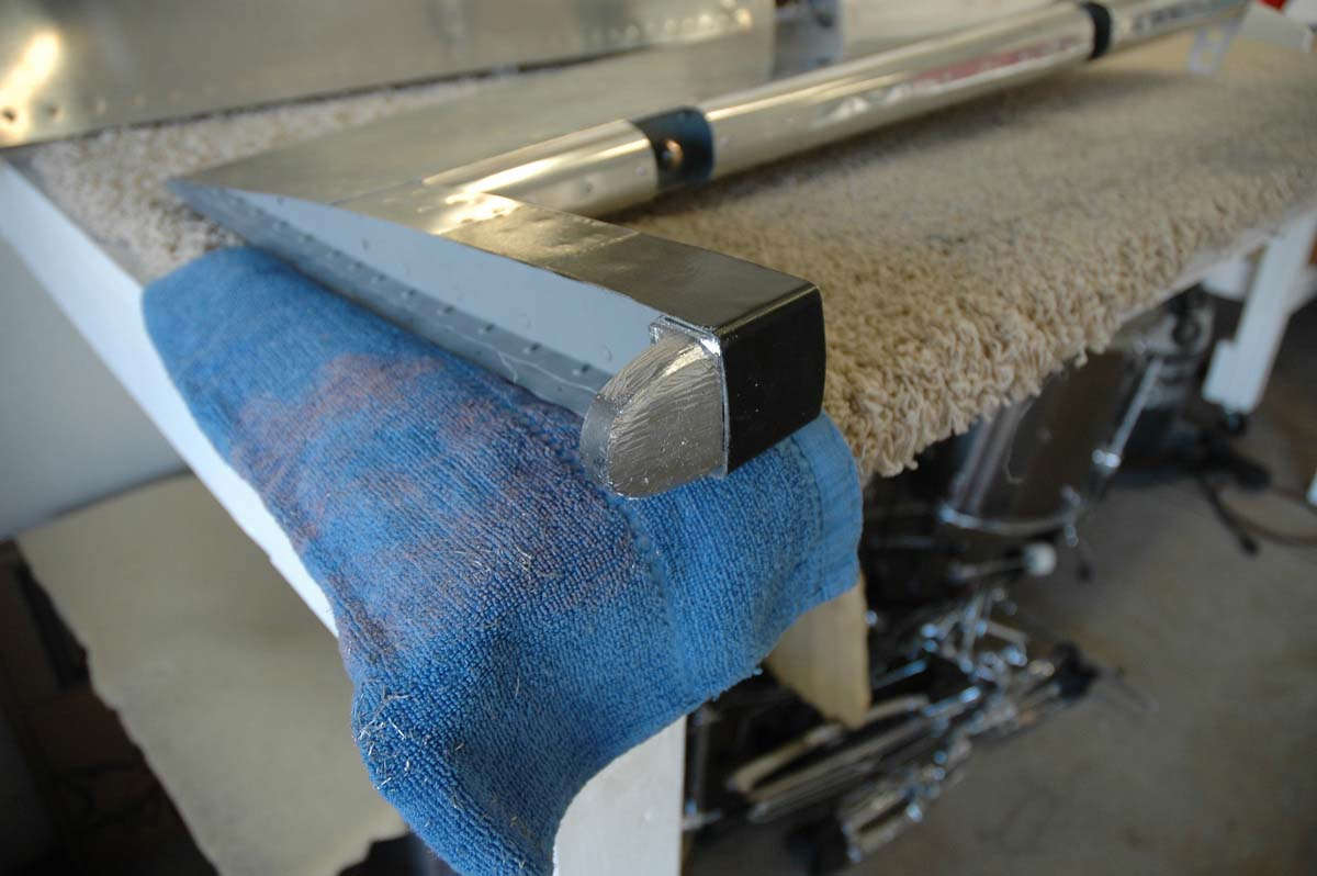
So, the next step is to do a rough attach of the rudder to the vertical stabilizer. Install the hinge bearing mounts into the rudder and fit them to the hinge mounts on the stabilizer, then adjust to the right gap between the two surfaces. Check for binding of the rudder. So I laid the rudder down next to the vertical stabilizer. Hey, an airplane tail just appeared. Pretty cool.
I studied the plans again carefully and noted that the bottom bearing mount is longer than the other two (the other two being the same part number as the elevator bearing mounts). Test fitted it all together, then constructed this little tool to screw the bearing mounts into the nutplates without damaging them.
I'd like to say I made up this tool, but I'm not that smart. Toad's page (an excellent help to me) on the subject pointed to Sam Buchanan's ideas on the matter. The worldwide web: couldn't build an RV-8 without it and all the guys who have done this already and have well documented it.
Well, I was all ready to adjust my bearings and my gap but I ran out of Sunday before I ran out of things to do. I shall return next weekend and finish the rudder up.
Augsut 23, 2009
I got back into it on Saturday and was finally able to finish up the rudder except for the fiberglass work, which will be done either sooner (if I have spare time before I start on the wings) or later (when I can get to it later). I suspect the former will prevail. I spent a bit of time figuring out how to adjust the rod end bearings. The depth is adjusted by tightening or loosening the bearing threads until the right gap exists between the rudder and vertical stabilizer. Took a bit of hit and miss. Not sure if it is even correct now. I shall have to take one more look at these after I talk to someone who knows what they are doing.
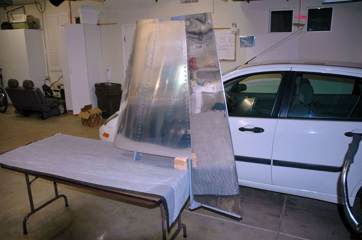
Here is the rudder and vertical in the middle of said adjustment.
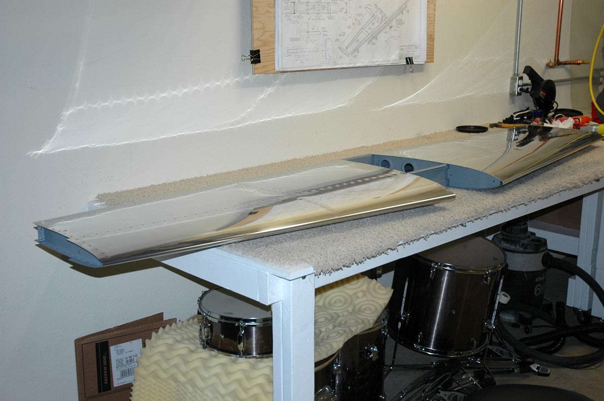
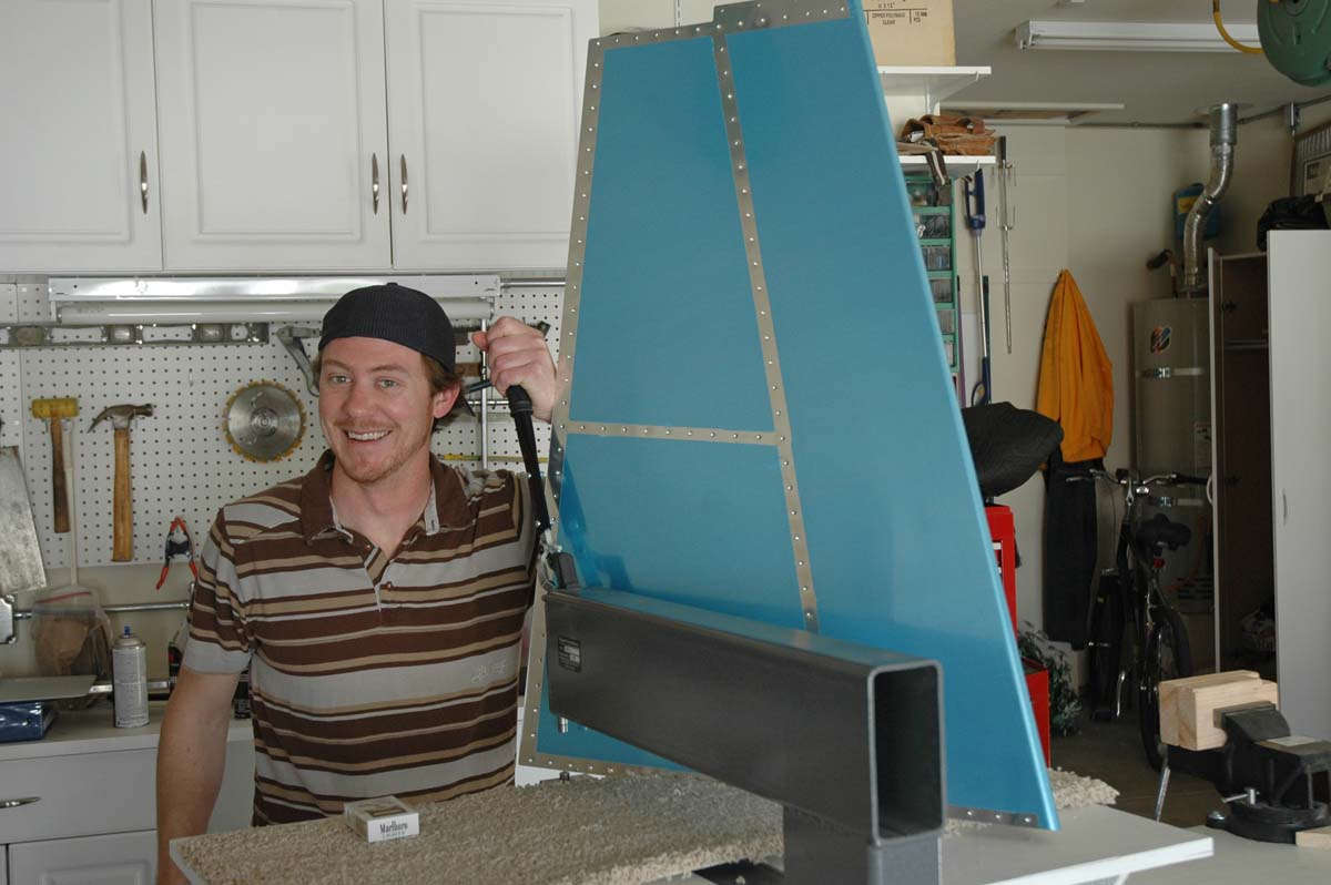
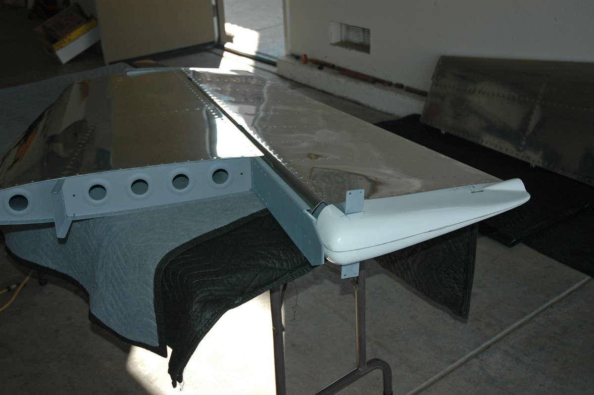
And, after all was said and done, I had to do the requisite "stand them on the table" shot showing the vertical stabilizer with rudder attached. Had to show my son, make airplane noises, move the rudder back and forth repeatedly...all the normal stuff.
On to the elevators.
When last seen, I had done some work on the elevator and then jumped back to the rudder. Well, got the rudder done two weeks ago and jumped back again to continue on the right elevator. Made some good progress through these weeks. Here's pretty much where I picked up again:
I had to do some more shaping of the lead counterweight in accordance with the plans...I had to remove a fair amount of material and did so with the magic vixen file that will also file off a fair amount of skin if one is not careful.
Later note to self, and anyone else reading this thinking they are going to learn something: trim only the counterweight for the right elevator. Not in the written instructions, and only a small note on the plans, is that the left counterweight should be left untrimmed to account for the heavy trim tab servo used for the electric trim.
After doing the match drilling of the skin and other components, using a #41 drill bit this time (keeps the rivets tighter than using the #40 as called for in the plans), I then deburred all the holes, dimpled all the skin parts, and matching understructure, and did the edge finishing and any remaining cleanup items. Then, off to the paint shop for some priming.
Then it was back to the assembly shop, where I started riveting the understructure together. All went fairly smoothly and quickly. Here is the elevator horn attached to the spar and the end rib. Not too shabby.
Wouldn't do without a close-up, now, would it? The spar and end rib and flush riveted together so the elevator horn will fit nicely. Once the elevator horn is attached the structure stiffens up right smartly.
Then, once the understructure is completely riveted together, it is off to the auxilliary paint shop for some primer touch up...nothing fancy but the rivet surfaces also get a touch of primer.
That all pretty much took the first weekend. I had a funny week last week, spending some time with the FAA DC-3 at Offutt AFB, Nebraska. Good show, had an unexpected opportunity to catch up with some old friends too. Got back in the early part of the week, and had a day to fiddle, er, work on the right elevator some more. Here is the skin clecoed into final position as I got ready to put the whole thing together.

All the rivets are squeezed, so it goes pretty quickly. After the rivets were set and everything looked ship shape, I decided to do a bit more touchup of the primer and add some gloss enamel to a couple of the to-be-exposed surfaces. So, back to the paint shop. Decided to use the auxiliary paint shop this time.
Then we had the challenge of the session...trying to roll the leading edges. Not sure why this gave me so much trouble this time. I think I tried to hurry it a bit and it bit me back. Scraped some skin off my fingers, too. Oh well, blood, sweat, and a few tears (actually, I didn't cry but I did get frustrated.) So, I put it away for a day before I got too frustrated and came back and worked a bit more patiently with it. Came out okay. Still seems to be more bend need than aluminum available, but I guess it turned out okay after all.
Another one of those close-up things...here working my way up the seam as I drill to size, deburr, and re-cleco and set with a pop rivet.
Okay, here's the baby good and done. Leaned up against the parts for the left elevator, the one with the (drum roll, please) Trim Tab. But before I thought about that, I took my right elevator to work for "show and tell." "Oooh...ahhhh" said everybody, but also I got one of my real mechanic guy buddies to use his little torque wrench and properly torque the counterweight nuts to the counterweight screws. Thanks be to Greg and his tiny torque wrench.
So, this past weekend, the three-dayer (i.e. Labor Day) saw me dive into the left elevator. The preparation and assembly is pretty much the same as the right elevator except for the (drum roll, please) Trim Tab. This has caused enough RV-8 builders grief that I will proceed very cautiously about the (drum roll, please) Trim Tab. However, the whole thing starts off innocently enough with the preparation of the tip and the counterweight, just like the right elevator. Here "we" are getting ready to drill the two #12 holes in the lead counterweight.
So I drilled and I clecoed and drilled some more, until at the end of Saturday I had the left elevator all final drilled and ready for the next step...deburr all the holes, dimple all the holes, edge finish all the edges, and then do some priming. Not sure if I'll use the primary paint shop or the auxiliary paint shop this time around. However, the (drum roll, please) Trim Tab has its own little spar and I mocked the trim tab up and figured how it was to mount on the elevator and pondered and thought and pondered a bit more (didn't drool) as the sun set in the west at Lincoln.
I 'figgered' I'd get back to it today on Labor Day, but I 'figgered' wrong. Too much other stuff to do....oil change, lawn care, brunch at Mimi's, thinking about the AFL-CIO, stuff like that. Didn't get back to it at all. Okay, next weekend, more work, maybe even get to the (drum roll, please) Trim Tab.
September 27, 2009
Well, here it is three weeks later. I encountered the dreaded trim tab and was defeated. I also was working on the trim tab spar, otherwise known as E-615 PP and oversunk the counter...so all in all it was not a good time. But, I have staggered along and gave Van's a bit more of my money and am proceeding a bit wiser for the experience.
First off, I was working on the E-615PP trim tab spar. All was proceeding smoothly. The bottom of this piece is dimpled to match the lower elevator. The upper surface, where it mates to the upper skin, needs to be countersunk to allow a smooth lower surface of the flange, to which the trim tab hinge will be riveted. Okay, dimpled just fine, then got out some scrap the same thickness as the spar and drilled some #40 holes into it. Set up the whole deal and carefully adjusted the countersink so the process would not make the countersinks too large, thus enlargening the holes. Tried it out, worked fine. Set up the real deal piece, drilled through each hole to allow the countersink tool to do its work. Confidently countersunk each of the holes on the upper flange.
Pulled it off the table. All the holes were enlarged. I had sunk them too deep. Hmmm. Well, I didn't actually say "Hmmm" but that was the idea. I scratched my head and thought about it. This piece is sandwiched in between the top skin and the trim tab hinge, which almost acts as a doubler. Would it be okay? Did some forum diving for awhile...some said it was okay in the process. In the end, I decided to pop for the $9 plus shipping and redo the part. Okay. Not the best example of how to set up work.
So, moving on from that mini debacle, I cleaned and primed all the parts of the interior structure (less the trim tab spar) and the inner skin. Waited a week to dive back in.
A week later, I dove back in. With both feet. Now, other guys have had fits with the little endplate in the trim tab opening on the left elevator. Van's designed this with two tabs that are bent 90 degrees and then riveted to cover the opening. The problem is, you get one chance at the bends. Screw it up badly enough and the skin is toast. The instructions are a bit hazy but I set the thing up as directed, after doing some more forum diving.
Okay, then. Started the process and bent the first tab. Used the rivet gun with the flush set mounted to run up and down the tab to crisply set the edge. The results were not great; the bend line was correct as far as I could tell but it left too much of the tab for the other tab to bend over very well. So I had to do some trimming on the bent tab. Frustration level went from Green to Yellow. So, after trimming the first tab, I carefully bent the second tab down and over it. Okay, not great again, but acceptable. Used the rivet gun to make the edge crisp. Looked okay; not great, but okay. Frustration level went from Yellow to Orange. I can make it better, right? Crisp that baby right up. Ran the rivet gun up and down the highway and got lost. Problem 1: the edge cracked. Problem 2: the wood I had set in to make the bends shifted or whatever, but the edge ended up crimped. Frustration level blew from Orange, right through Red, and into the Infrared zone. I stood there and couldn't believe it. Wrecked that whole skin with a little "I can make it better." I'd like to say I took more photos but as the frustration level rose my desire to document my screw-ups diminished. But just for posterity's sake, here are two of my completed handiwork:
The photos don't do the screw-up justice. It was not salvageable for even crappy work.
I put the whole thing away, totally disgusted with myself and with the left elevator. Bummer.
The next day, after licking my wounds, I decided that all I could do was order a new elevator skin and rebuild the thing. Bummer. Ordered another skin ($65 plus shipping) and started taking my old elevator apart. Drilled out a bunch of rivets. I'm getting good at that.
Went off to fly the DC-3 again...this time to an airshow at Scott AFB in Illinois. No RV-8s or any RVs present at the show. No WWII warbirds save a lone P-51. Some good flying by the USAF and USN guys, and a good show for the RCAF Snowbirds. At least on Saturday; Sunday it rained and the flying was cancelled.
Back to Lincoln, and what should be awaiting me is a new, virgin, E-615PP spar and new, virgin, left elevator skin. So, lets see what I can do with these. Did he learn from his mistakes? Well, I had already decided this "bend the tabs" idea wasn't going to fly for me. I had done some forum diving and found that guys had made little "riblets" for both the elevator and the trim tab itself (which also has some bendy tabs). Okay, sounds good. Make some riblets and remove the "one chance" bend idea.
So, this past week, I did all the prep work on the skin. Dimpled and deburred, edge finished and back riveted. Went quickly, almost like I had done it before.
The fly in the ointment looming on the horizon was that I would have to do the trailing edge bend again. As dedicated reader(s) know, I had originally used the Van's bending brake design the first time around. Didn't work so well. Keith Peterson, an experienced RV guy, had offered to bend my edges at his shop at Grass Valley airport, and his way worked much better. So, instead of calling on Keith again, and knowing that someday I will have to bend ailerons and flaps, I set myself up with the same setup that Keith used. (That's the Van's bending brake in the background; not good for much.)
This bending method entails the use of two pieces of angle iron. One is mounted to the workbench with screws. After the skin is firmly taped into place to eliminate it shifting, the second piece of angle iron is clamped over the bend line and the clamps are slowly adjusted to make the bend.
I bent until the edge distance was about 1/4" or so, as I could remember what Keith had bent to. I experimented a bit, took it apart twice to ensure I didn't overbend. This is another thing you don't get chance #2 with: if you overbend you can drive the stiffeners into the other side of the skin and maybe even crush the trailing edge. Don't want to do that.
But it worked out great and the trailing edge is as straight as a baby's ruler.
As I was doing this, I would glance over to the old skin, looking back forlornly from the other workbench. "Too bad" I would say to it, "you had your chance." I consider it a traitor to the cause, and won't talk to it anymore. It apparently isn't talking to me anymore either.
So, I reassembled the elevator again to make sure everything still fit, and also to fit in the E-615PP trim tab spar.
I took great pains to set the counter sink, practiced numerous time, measured many more, and then did the final drilling. Took it out, found it to be a bit shallow. Adjust a quarter turn on the countersink tool and redrilled. Okay then, fits good and works just fine. Primed that part and set it aside.
So, while the elevator was in front of me, I designed my little elevator riblet. Measured and cut, used paper first, made a couple of adjustments, and then mocked up the part with my mock-up stock (cut up manila folder).
Looks good. I felt like what Ed Wells must have felt like when he designed the Boeing B-17. This should work. Just turn it into metal. How hard could that be? Next time, we shall find out.
Oh, yeah, and I ordered the wings. Should arrive in early December. This has all the makings of really building an airplane.
October 4, 2009
Good week behind me. Got a chance to spend two long sessions on the left elevator, and made a few changes to what Van's wants done with the elevator and trim tab edges.
As noted last time, the bent tabs sealing up both the elevator and trim tab edges seemed less than ideal. Lot's of guys have done this part without problems, but more guys have seemed to have had problems making it work right and look right. So since I had some major problems with the elevator here, in fact causing me to redo the skin for the left elevator, I tried an approach used elsewhere: make some riblets to replace the bent tabs. So I made some templates, as noted last time, then built one little riblet myself and had some help with two others (thanks, Greg!).

These will fit into the openings and I'll use some MK319BS rivets, otherwise known as pop rivets, to secure them. Here is the inside trim tab riblet fitted into place:
Like I said, I think it is a cleaner installation. And here is the little riblet drilled and dimpled and riveted onto the trim tab spar.
So, after that was assembled and primed, I was basically ready to rivet (again) the left elevator. All the rivets are squeezed using the pneumatic squeezer, and all but a few are AN426AD3-3.5 rivets so it moves right along. Turned out pretty well. I worked up and down the rows of rivets pretty quickly and I thought to myself this is going too easily. Just then I mucked one up and had to drill it out. Says something about the power of suggestion.
So, here is the left elevator pretty well done (need a few more pop rivets and I need to bend the leading edge) laid out next to the trim tab, in progress. I spent much time making sure the trim tab will fit properly. One advantage of doing the trim tab with riblets is that you are not committed to the width of the tab until the end. You can adjust the left edge of the tab so it gives at least 3/32 inch or greater gap between the elevator and the tab in controlled situation. Just trim a bit more as needed until the edge is right, and then mount the riblet.
And, another view from the other side.Note that the rivets on the top of the trim tab spar are done in conjunction with riveting the trim tab hinge into place, thus they have not yet been done here.
I have the trim tab mocked up pretty well where the bottom plates are mounted to attach to the servo, but forgot to take a photo. Hopefully, this coming week will allow me to: 1) roll the leading edge (not looking forward to that); 2) complete and mount the trim tab; and 3) install the servo and associated stuff. Basically, finish the left elevator. By the way, the measurements on the plans for installing the servo on the inspection plate are wrong! wrong! wrong! so a word to the wise: get it all laid out for real before mounting the servo on the plate. I could tell right off the bat that if I followed the plans the servo would not line up properly with the trim tab.
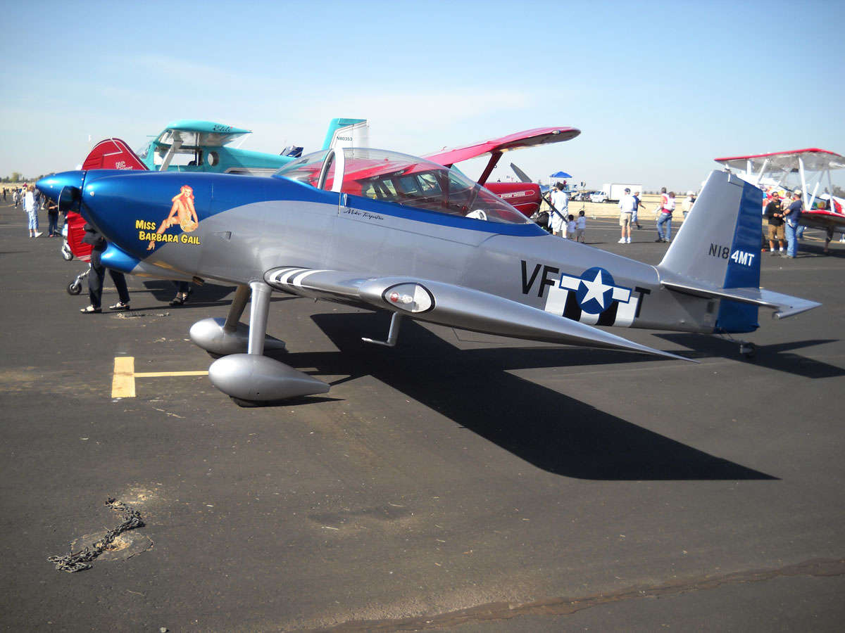
Saturday was the Lincoln Air Show so I took a bit of time away from the elevator to run out to the airport for an hour or so, hoping to see an RV-8 or two. Glad I did, as Mike Terpstra and his son and his RV-8, N184MT, were there. Beautiful airplane and equipped like I hope mine will be someday: 180 hp injected with constant speed Hartzell; fairly basic panel and lean interior. Same sort of paint, also, in that I am drifting away from polished aluminum and toward aluminized paint. Mike finished this airplane two years ago after taking five years to build it. Based at the Modesto airport. Nice guy, beautiful airplane; what else can be said?
Maybe I'll make the Lincoln Air Show in 2014 with my RV-8.
Note for reader(s). I added an RV-8 area to my Aero Vintage Books Forum page if anyone wants to make comments or add feedback, etc.
October 19, 2009
Well, it's two week later. I spent a good deal of time working and didn't want to take the time to update my little website here. But off I went to Denver for my work, so now would be a good time to catch myself up. When I wrapped up my sessions in early October I had pretty well riveted it together, all but a couple of hard to reach rivets and the hinge that attaches it to the elevator.
So, here is where I picked up week before last, lining up the hinge and trial fitting it.
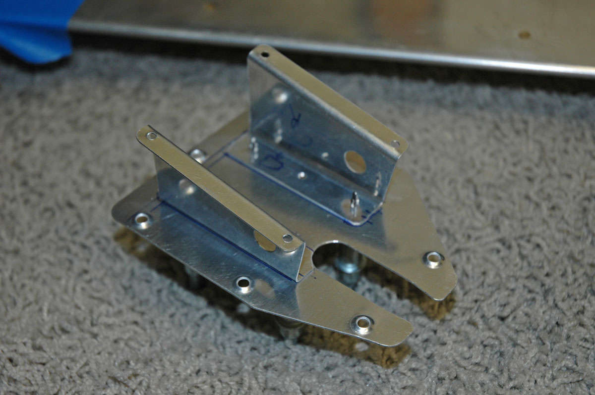
I did all the prep work and drilling to fit the trim tab control horn into position. It is actually two parts that are riveted into position as one part.
I riveted most of the trim tab together and then set it aside to get some advice on some hard to reach rivets; the question: pop or agonize over how to get in and set them with a rivet gun.
So, cogitating over that, I moved on to roll the leading edges of the left elevator. Took a tip from another site: roll the thing in sections. I did that and it proved to be a bit easier. Still not great...there seems to be more curve than skin, but I guess that is the way it is supposed to be. Here is my pipe and my Gorilla tape at work.
So here it is coming together, the trim tab clecoed in place with the hinge in a final fit, and also the control horn in position.
So I then turned my attention to the trim tab servo that mounts on the access plate that fits on the bottom of the elevator. As noted at the end of my last entry, the plans are wrong as far as setting up the servo mounts. If you follow the plans, the opening for the servo does not line up with the trim tab horn...not even close. So I set it up in real time and still had to adjust the horn a bit to make things fit correctly.
So, here is the other side of the access plate with the servo mounts clecoed. Good to go.
And, here is the servo test fitted in the mount.
So, happy with all, I riveted the thing together. As per other site advice, I used the NAS1097AD4-3.5 rivets allowing me to countersink them with a deburring tool vs. dimpling. Smaller head, larger shank. Looks better.
Back to the trim tab, here it is pretty well done. Ended up making the agonizing decision (actually, not that hard) to use pulled rivets vs. using the rivet gun for the hard to get to rivets.
Here is a detail shot of the little riblets and how they fit into the structure. And, hey, look, two pulled rivets. These two were actually little buggers and I had to drill one out. The problem was pulling it close to the trim tab spar as the rivet is finalized. These are not structural parts...in the original design, these are the folded end tabs riveted together.
And here is the purty little thing riveted onto the elevator...finally. Seems like it took forever to get to this step. Not sure why.
And another close-up view of the inner edge of the trim tab with the riblet and three pulled rivets holding the riblet in place.
Then it was on to fitting the trim tab servo into place, with the push rod trimmed to fit and then connected to the trim tab horn. Pretty straight forward; another of those measure three or four times and then cutting progressively to avoid cutting too much. Worked out fine.
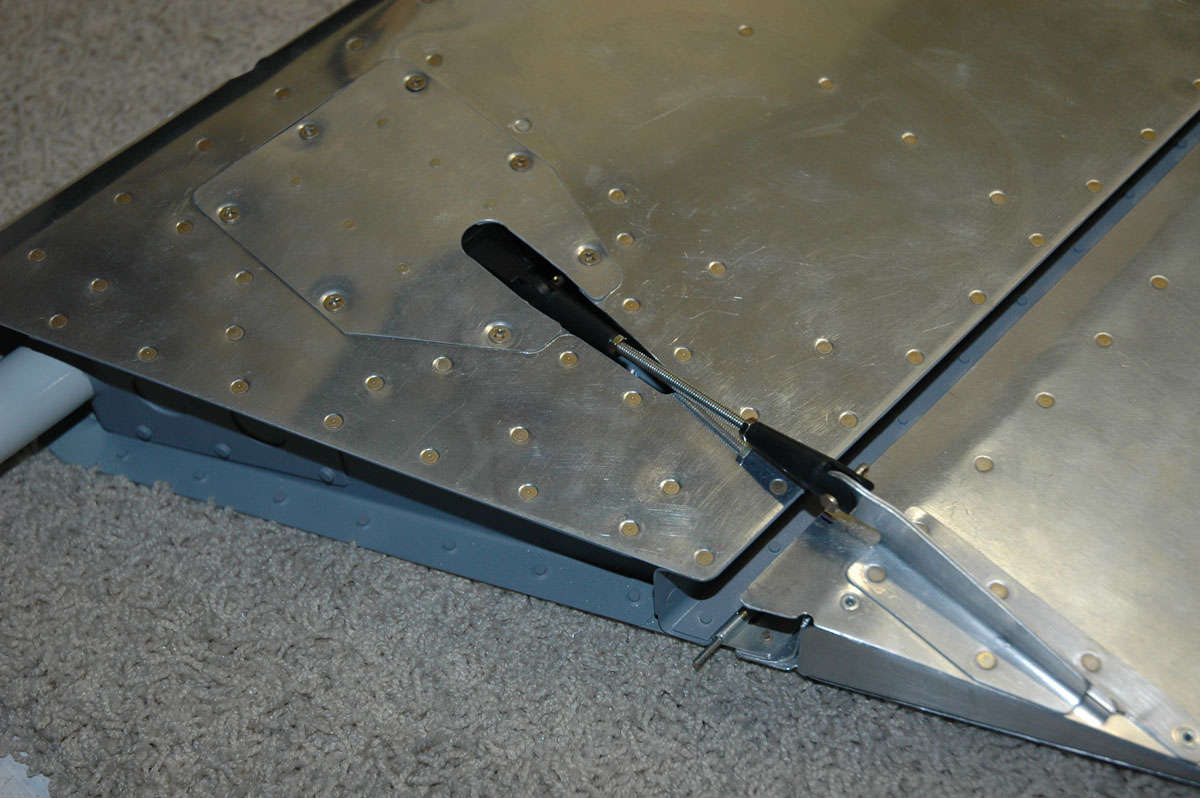
Another view of the whole thing fitted and pretty well done. The servo instructions advise that one can use a 9-volt battery and power the servo to check its freedom of travel. Plus, I found out, it's cool to see something on the airplane work. As it turned out, I needed to trim the pushrod opening a bit to make it work without interfering with the cutout in the skin.
So, here it is pretty much together...trim tab attached and elevator basically done.
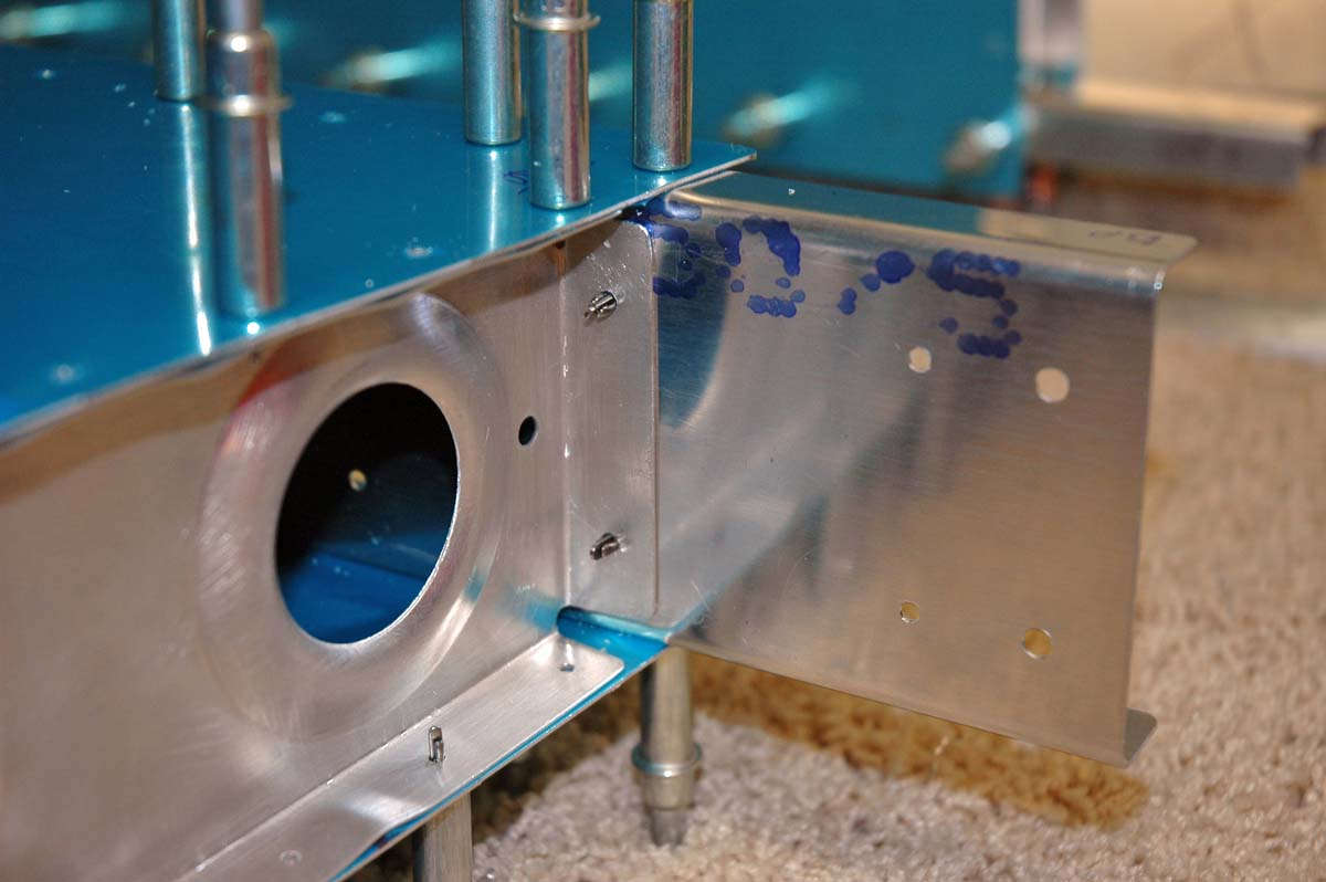
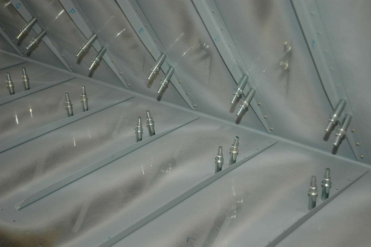
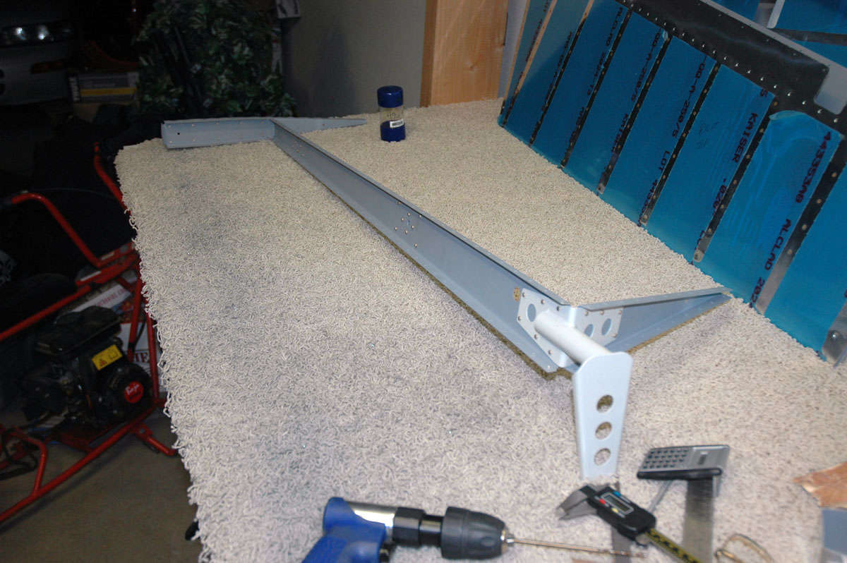
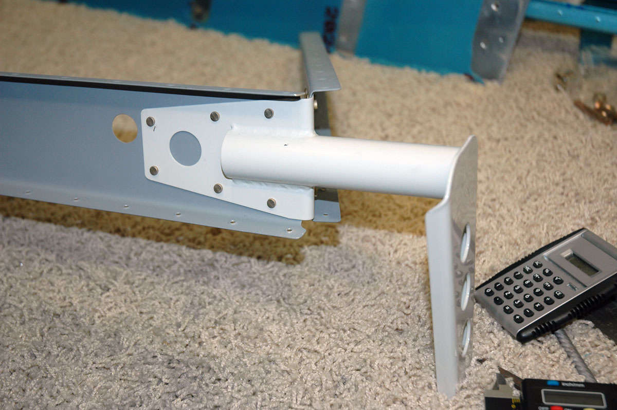
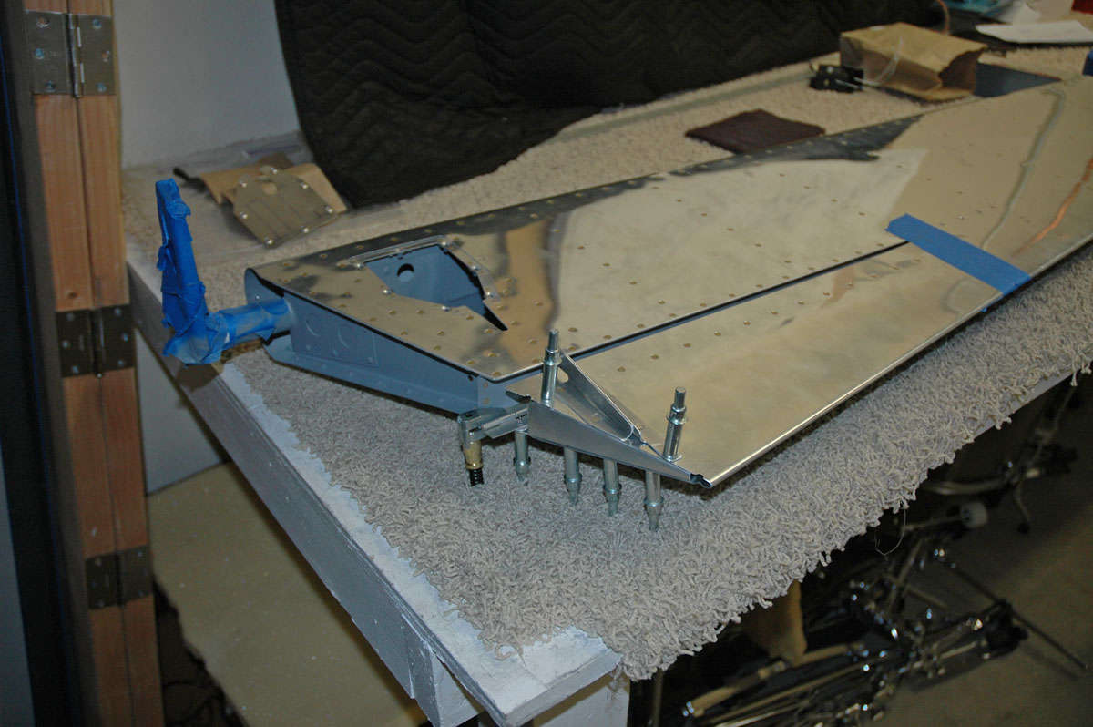
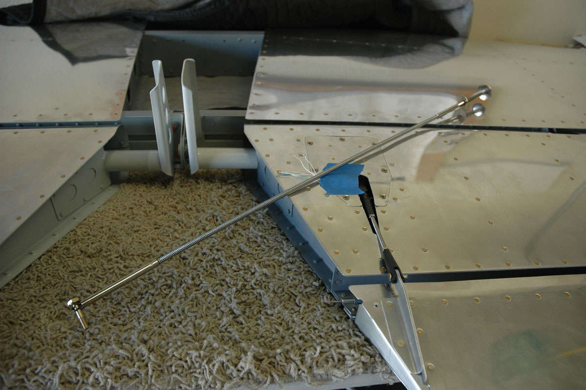
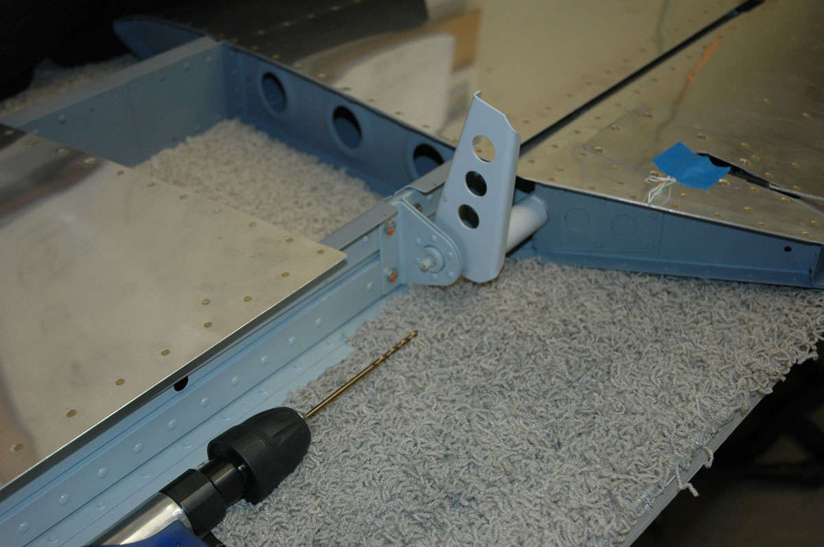
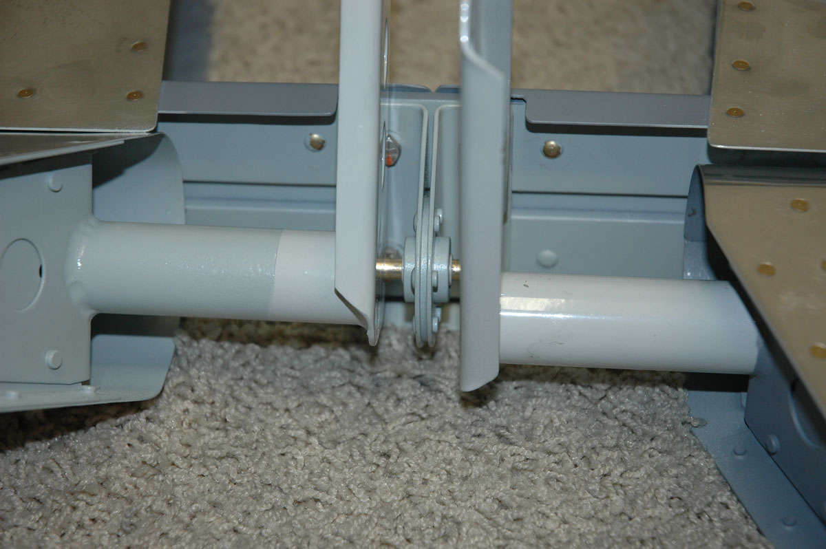
So, what's next, then. Well, I pulled the horizontal stabilizer out of the rack hanging from the ceiling and did some trial fitting of the elevators to the horizontal stabilizer.
I carefully adjusted the rod end bearings to specs, then found the specs were too tight and modified the specs a bit so it would fit correctly. I aligned back and forth, from elevator to elevator to make sure the positioning was correct. I measure at several points from the aft edge of the horizontal stabilizer to the trailing edge of the elevator.
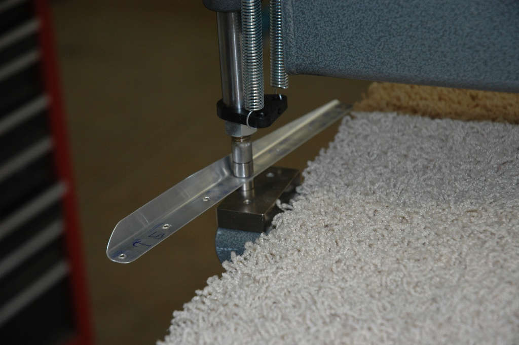
Once I got to the part where I am trying to insert the bolts into the hinges/rod end bearings, I used a trick I utilized on the rudder: this little parts retriever will hold the bolt and allow it to be positioned for insertion.
Once the bolts were in and I was happy with the alignment, I marked the tips of the horizontal stabilizer where the skin needs to be trimmed to allow the elevator to travel up and down. Marked and masked, I did rough cuts and then filed away until I was happy. Edged it and sanded and rechecked: worked fine.
Next up: confident of the elevator alignment, one needs to drill the elevator control horns to accept a bolt through each horn and also through the center elevator hinge. Confidence is overrated; measure and think, think and measure. Use a nylon bushing, ala Lowes, to align the drill with the bearing and avoid tearing up the bearing. Drilled pilot hole in one horn, then drilled it out to 1/4 inch to accept the bolt.
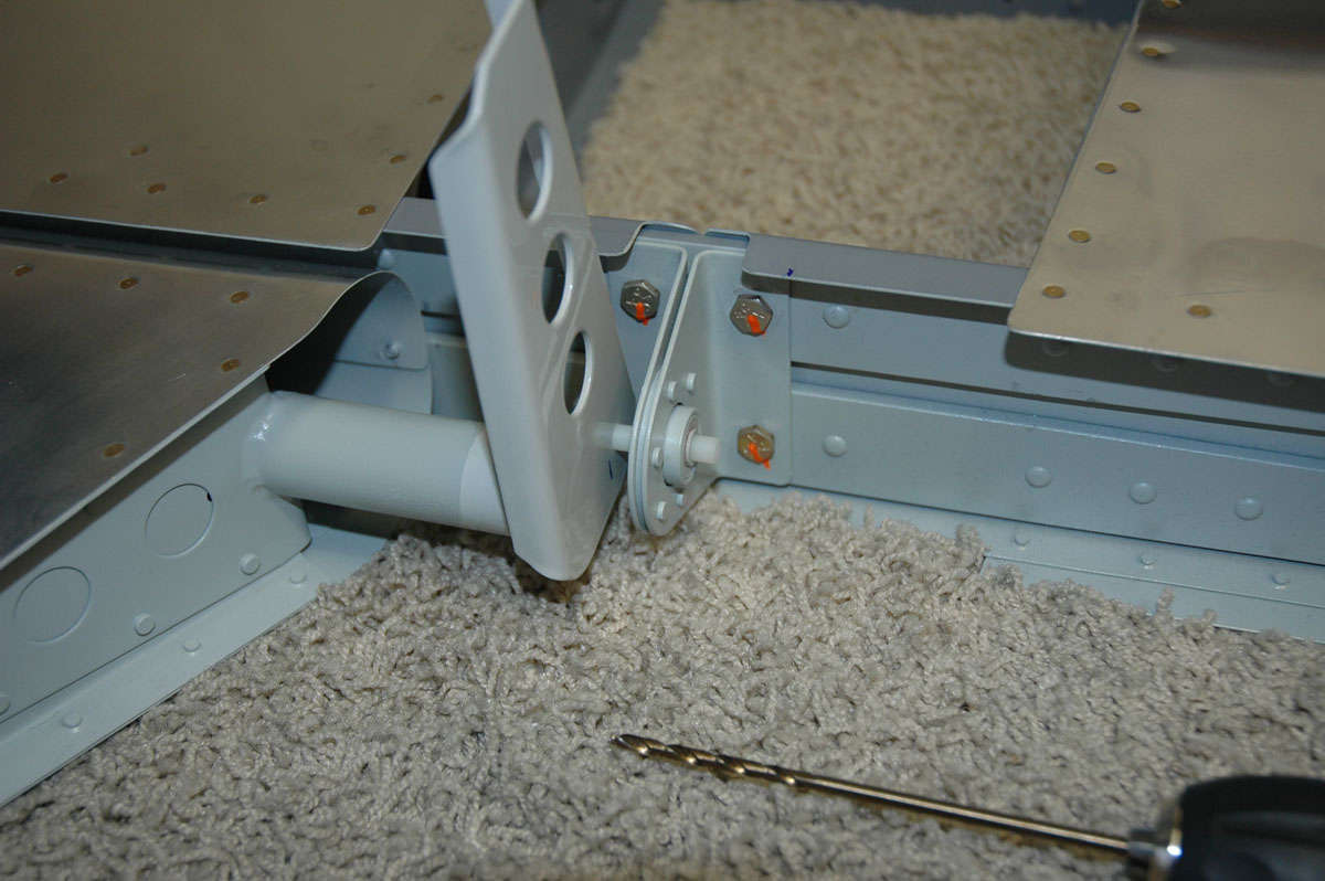
Did the other side.
Fitted it all back together. Inserted bolt; fit fine; looks good; what, me worry?
And that's how my two weeks and, more specifically, my last Saturday ended. I felt pressure, internally driven, to get this assembly completed and put away. Started to rush; started to get frustrated with my imposed deadline; other things to do. Decided to stop. Come back next week. Don't want to rush. Don't want to make a mistake, well, more mistakes.
Wings should arrive the second week of December. A few things I can do before they get here that will be productive like design a wing stand and figure out how to organize the inventory. I can always go back and do fiberglass tips of the tail section if I get bored. Doubtful.
November 2, 2009
So, flew a week on business, then spent last weekend on B-17 stuff that wasn't RV-8 stuff. Okay, then, and then a busy following week trying to catch up on "stuff," whatever that is. So, for the RV-8 project, that left a bit of time, maybe five or six hours, that I was able to dedicate on Saturday. Then busy on Sunday and here I am in Medford, Oregon, flying again and not working on my RV-8. But, alas, earning money for mortgages and food and a bit for the RV-8, so it is connected.
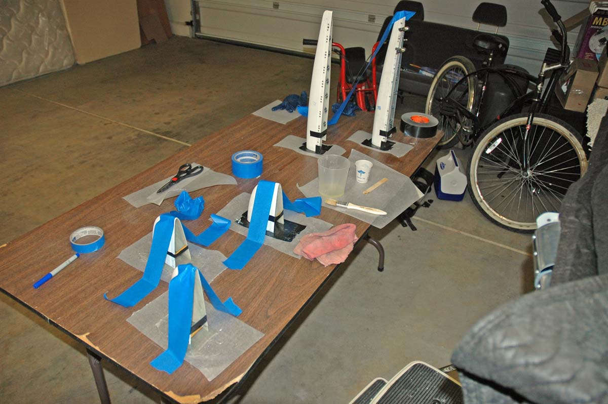
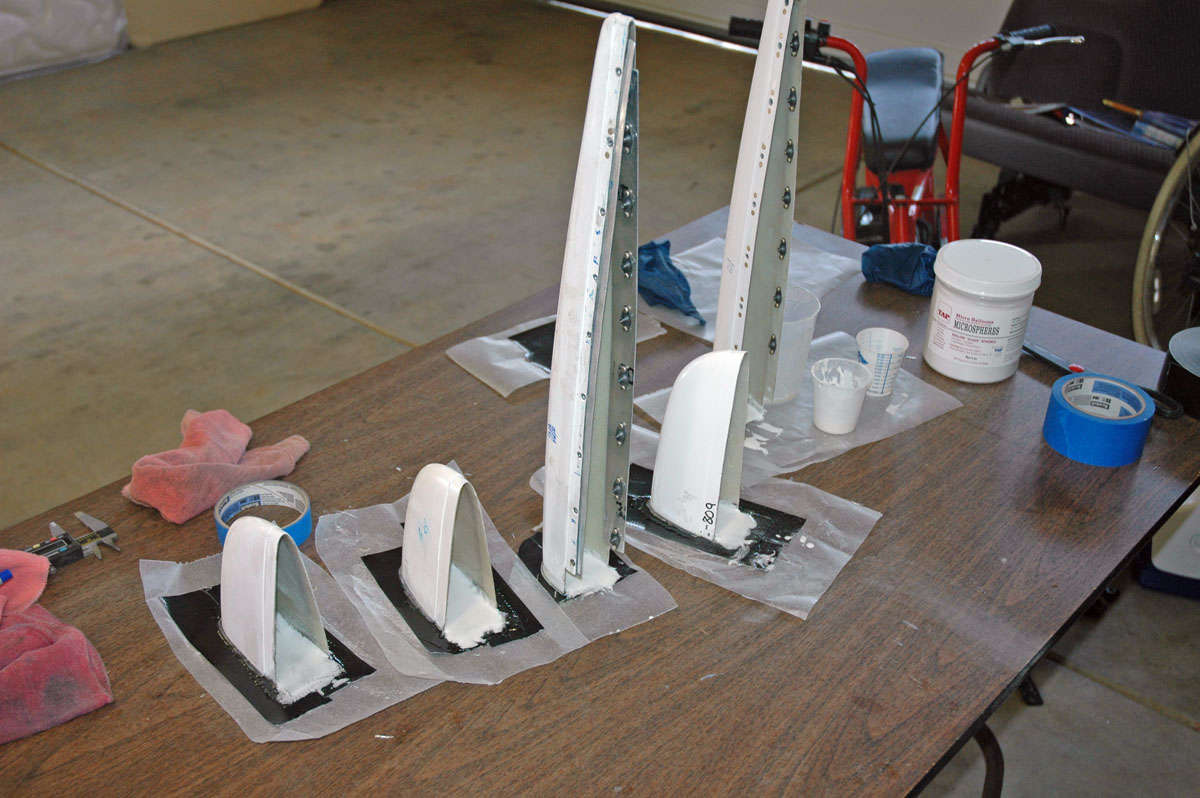
Back to the task at hand, I had spent some good quality online time here and there researching the wonderful world of fiberglass. Something I've never done before, so it an educational opportunity. On Saturday, I got all the empennage tips out and starting putting thought to action.
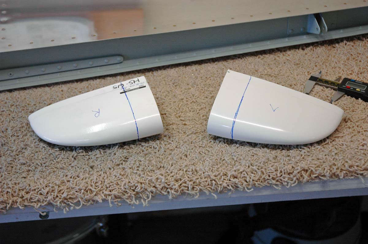
Here are the horizontal tips. There are several decisions to be made here. The Vans Plans call for the builder to simply ("simply" being a relative thing) blind rivet the tips and then do some filling and smoothing the seams that make the transition to the metal parts. Others suggest using nutplates and screws so that the fiberglass is not permanently attached...thus easier to repair or remove if needed. What complicates both approaches is that the horizontal stabilizer and elevator tips have ends that are open that really should be closed in, both for aesthetic and aerodynamic reasons. So, whichever way it is done, you are probably going to get to deal with epoxy and fiberglass cloth and hardeners and other such things.
And the fiberglass world can be a confusing one, indeed, what with so many different types of epoxies and resins and peel plys and glazing compounds and fiberglass cloth and fiberglass tape and Elmer's glue. Well, I just made up that last one but you probably can do fiberglass with Elmer's glue, just not on my airplane.
So, I pondered and thought and initially decided to go the nutplate and screw route, primarily because I want to be able to get the elevator tips off if I need to adjust counterweights, and to provide access to the rudder bottom (navigation light) and vertical stabilizer tip (VOR antenna?). So I went ahead and order a bunch of hardware...nutplates and screws and other stuff from Vans.
Last Saturday I got all the fiberglass parts out and started fitting them.
So, I measured and marked and pondered a bit more, this being the elevator tips that have to be cut down a bit to fit around the counterweight.
But, you can only do so much 'sticking your toe in the water' before it becomes time to dive in. My Dremel tool, carefully used, makes the needed cuts.
Here are the cutouts on the rudder bottom tip; the cutouts allow the fiberglass part to fit around the elevator horns.
As for the elevator tips, the fiberglass tip fits around the counterweight, and the forward end of the counterweight is the part that needs to be closed in with fiberglass.
Trouble is, if you are going to attach the elevator tips with screws, the fiberglass has to fit around the counterweight without being attached to the counterweight. The only thing I could figure out is that the counterweight has to be filed down to provide the room for the fiberglass build up. This is okay for the right elevator as it is nose heavy; not so good for the left elevator as it is a bit tail heavy with the trim servo. More on that later.
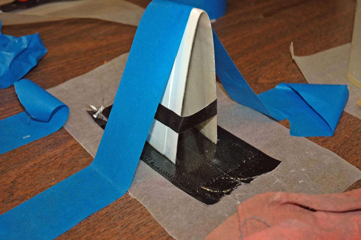
Here is the rudder bottom fit into place. As I worked with the parts I modified my original thinking: at this point I intend to permanently attach the horizontal tip and rudder upper tip (possibly) and use the nutplate/screw arrangement for the rudder bottom, elevator tip, and rudder upper tip. Until I think about it more, I guess. There will be some careful fiberglass work to make some of these parts fit better. More to come next time.
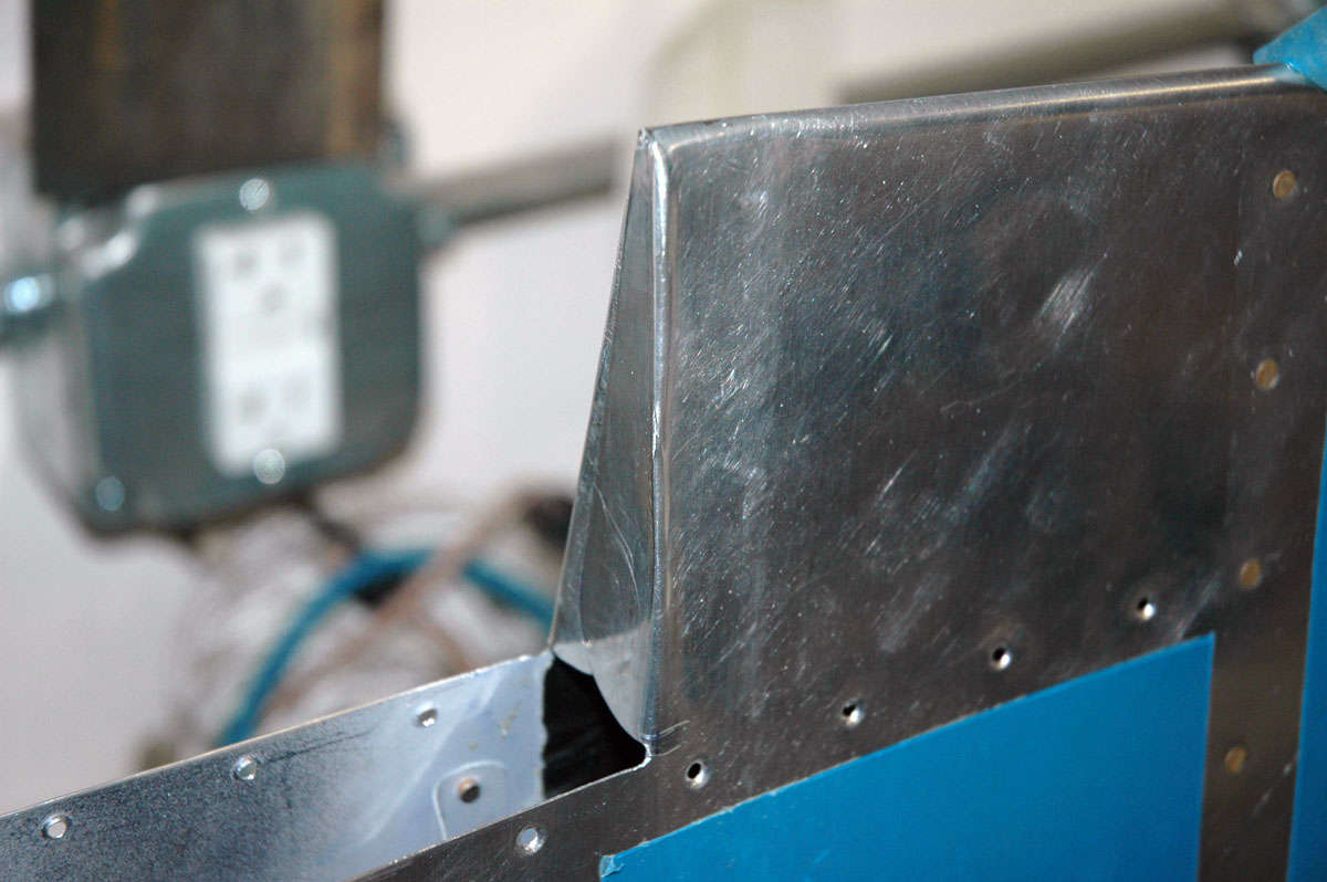
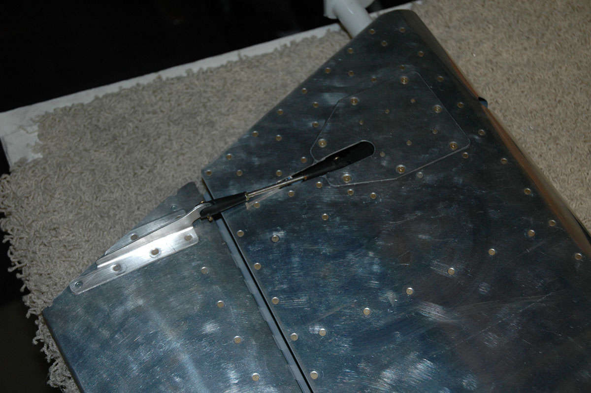
Speaking of fitting, I took the time to fit the rudder according to the Vans Plans (three different tie rod distances for each of the three hinge points). Worked out pretty well, except I'm not pleased with the gap between the rudder and vertical stabilizer at the top. Seems a bit tight to me and is not quite even. I think if I readjust the top and bottom tie rod lengths I will bring it closer to the ideal.
So, that's about it for a Saturday session. Except I ordered some fiberglass supplies from Aircraft Spruce, but will purchase the epoxy and hardener from a local supplier to avoid paying for "hazardous" material shipping. There is a local plastic shop that I will visit soon.
November 10, 2009
So, I am learning about fiberglass, and not necessarily in a good way. Before I get too far here, I did go to my little plastic store, actually Tap Plastics. Got a bunch of stuff, including epoxy and fast hardener, plastic cups and mixing sticks, and spreaders, and other stuff. My order from Aircraft Spruce arrived with more fiberglass materials. My order arrived from Vans with nutplates and other hardware. All this stuff piled up on my workbench staring back at me.
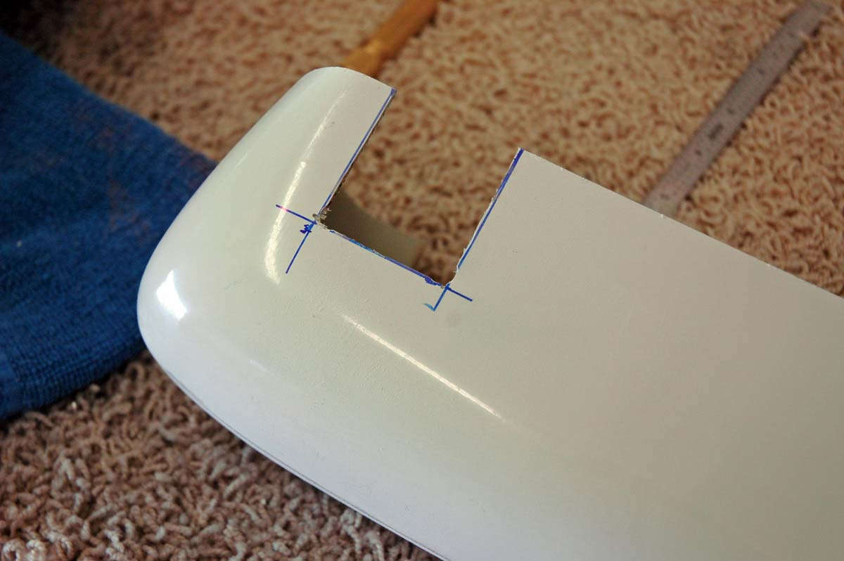
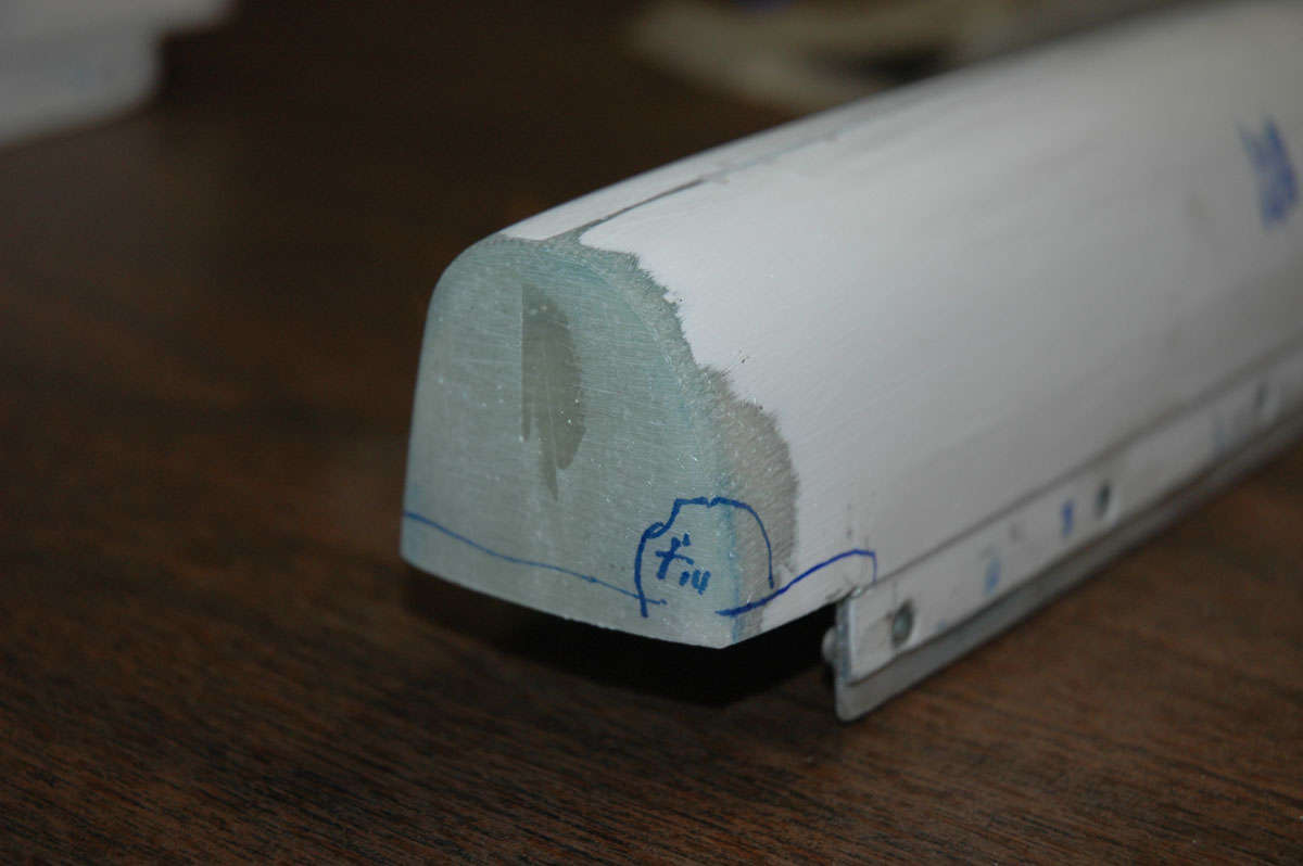
So, I had already done some test fittings of the tips, and all fit pretty well except the elevator tips. It seems the end rib flange interferes with the way the tip fits. Some web sites note that the plans tell you to trim the end rib back to allow the tip to fit, but I could not find that instruction.
There is a planview (Detail H-H on Drawing 5) that shows a 1/2 inch overlap between the skin and the tip, but that doesn't really tell you much. This photo shows the problem: initially, I thought the flange was interfering with the fiberglass tip fitting; as it turned out, I think it was only the line of rivets. Hindsight is 20/20, though, as this tale continues.
Anyways, it was too late to do any trimming on the tip rib. Reading some other sites, I knew that if I trimmed the fiberglass tip to fit I would have edge distance problems, but that I could use an aluminum backing strip with the nut plates mounted to make it work. So, I dutifully trimmed the fiberglass tip so it would provide clearance between the flange and tip; so far so good but, sure enough, there were issues, like edge-distance issues. Not surprised.
So, I proceeded to manufacture two aluminum "doublers", planning to epoxy them into place and then mount the nutplates through both the fiberglass and aluminum. Epoxy in progress; not a virgin anymore. Maybe I should have stayed one.
Came back the next morning and released all my clamps. Aluminum doublers were very secure. I was happy. Did a test fitting, again, and the doublers now were interfering with the line of rivets. Took some careful measurements, something I should have started with. I realized the flange was not the problem; it was the rivets. I had to trim the doublers back a bit to make it fit. Put it on the sander to make a nice neat trim. I think the heat from the sanding action caused the epoxy to fail, and the doublers started to come loose. I wasn't so happy. Okay, plan B. I had been smart enough not to do both elevator tips at the same time, so this process continued with only one tip. I decided to 1) do new doubler strips with the nutplates attached, measured properly, and then epoxied into position, and 2) do the other tip differently. Okay, made the new doubler strips and drilled for the nutplates.
Riveted them into positon, and here is the completed doublers ready to be expoxied.
I then started on the other tip. Decided to trim only enough off to allow the edge of the fiberglass tip to remain clear of the line of rivets. Okay then, use the Dremel and trim the fiberglass.

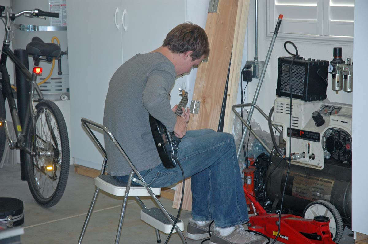
During this process, my son Nathan came out to the garage to keep me company and do some guitar work. I think he is secretly writing a song about building an RV-8 but he is keeping the secret well. Haven't heard the song yet but it might be so secret I will never hear it.
So, drilled and prepped the tip for the nutplates to be riveted into position. Various websites warned about using the hard rivets in this process; others said only to avoid oversqueezing...all you are trying to do is set the nutplate into position. The rivets don't do much more than that as the screw through the skin and fiberglass to the nutplate is doing the work. Sounds good to me; don't oversqueeze the hard rivets.
Riveting went fine, or so I thought. I had to work at the very aft nutplate and ended up epoxying the rivets into place vs. squeezing them due to access issues. By the way, one thing I had to do was to offset the very aft rivets, top and bottom, to avoid the nut plates sitting back to back. I redrilled a new hole a bit forward of the pre-drilled hole on the bottom of the elevator to make this work. Besides clamping, I also used screws through the fiberglass to the nutplates to pull everything up tight while the epoxy set up. Figured the screws would break loose easy enough even if there was residual epoxy that got the screws. Figured wrong.
The next day, I went to unclamp everything and remove the screws. All worked fine except two screws: one snapped in the process of removing it, and the other stripped out the screw head. Bummer. Had to get screw extractors and that didn't work very well with the stripped out screw. Had to remove that nutplate and replace it. Not easy, not pretty, but I think it is okay after all.
That last part came a bit later. First of all, after the tips were done, I figured I would start glassing in the open ends. Got me some foam and used Gorilla tape and set up the two tip ends to add some fiberglass cloth. Planned it all out. Mixed up my first real batch of epoxy and got my cloth, my Bondo cloth, and started to work.
All progressed okay for about 20 seconds, until the fiberglass cloth began to dissolve. Hmmm. That didn't seem right. I messed around with some fiberglass ribbon strips and tried to salvage the situation but decided that wasn't going to work. Meanwhile, my epoxy mixture was undergoing an exothermic reaction, a quaint way of saying it was heating the hell up and starting to melt the plastic container I had used to mix the epoxy. Hmmm. That didn't look right either. Moved that little smoking container out to the side yard to let it do its thing. Lesson learned. Punt for this session.
Regrouped two days later. Did the screw extractions as noted above, and decided to use plan C. Got new fiberglass cloth. Adopted another method noted on a website...can't remember which one, but this technique basically lays down epoxied fiberglass cloth and then attaches the tips to them. After it sets up and cures, the inner surfaces of the tips are built up with more cloth and epoxy, and then the thing is trimmed and sanded to fit. Looks easier to me so that is what we are doing here. The blue tape is an effort to press the tips down into the fiberglass; not sure if it doing much but I get an "A" for effort. I did the first two of the set-ups laying the fiberglass on waxed paper. It occurred to me about 2 minutes too late that this might not work to release the epoxy when the time comes. The Gorilla tape works well in not adhering to the expoxy, so the last three were set up on the Gorilla tape.
And here is another view. This is the horizontal tip and the fiberglass cloth is sized to accommodate the tab that will fit into the tip rib flange eventually. Stay tuned for more on this process. Over the next few days I will find out if this is going to work. Also in the next few days: attach the rudder tip with nutplates and screws and do the prep work on the fiberglass. Also, I want to finally adjust the rudder to vertical stabilizer distance so that the upper clearance will be better. Plus, a few other odds and ends while I get ready for the wings to arrive.
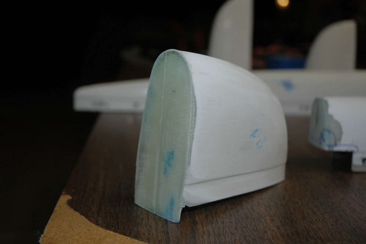
Well, picking up where I left off last week, the process I used worked pretty well to close in the ends. This is the elevator tip with one layer of fiberglass attached...sort of the starting point for the rest of the process.
And here is one of the horizontal stabilizer tips with its first layer attached. I've done a rough trim of the fiberglass edge with a closer trim where it fits so I can check the fit.
So, then I mixed up some more epoxy and laid some more layers on the outside edge and then added some microbubbles to some expoxy to build up some of the interior areas. This will, I hope, allow me to trim and sand to the shape I need. All new to me, so this is learn as I go.
And this is one of the elevator tips. This was the most challenging to do if one is adding nutplates to attach, because the tip must fit over the counterweight and not be attached to the counterweight as it could be if the tip were to be riveted into place. The counterweight needs to be filed down to allow the forward part of the tip to fit, and there can be little internal fiberglass added to the tip where it fits over the counterweight to allow it to fit properly. This makes for thin fiberglass. Here, I have marked up the area where it fits over the counterweight, thinking I could add a bit of filler to close up a small gap. That didn't work out too well, as it turned out, but I tried.
Getting closer with the horizontal stabilizer tips. I had to build up the end piece unevenly to make it fit square in the area where it meets the elevator tip. Not a problem, just laid two more layers on half the end piece to bring the surface up evenly, if that makes any sense. Hard to describe.
Fitting it all into place resulted in this. The vertical tip fits higher than the rudder tip, not an uncommon event from reading other sites. Some guys build the rudder tip up using microbubbles and sand to fit. I scratched my head a bit and decided to lower the vertical tip a bit instead.
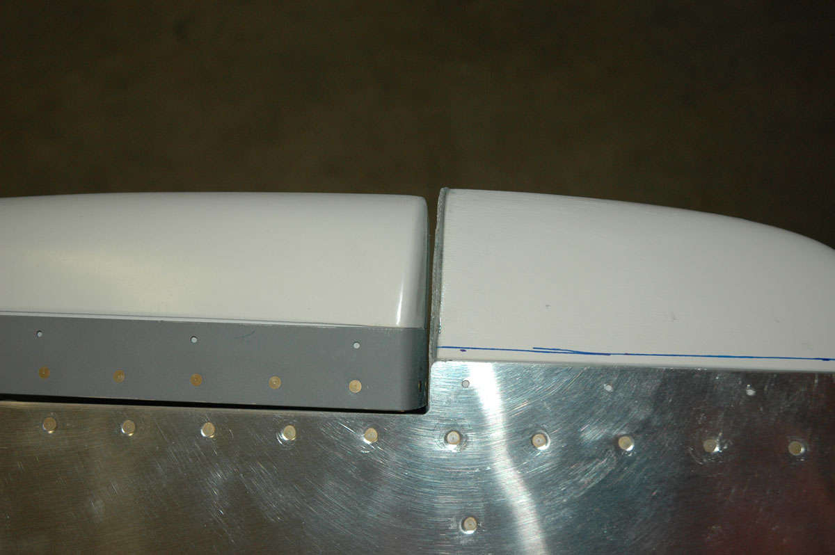
So, I measured the amount I wanted to lower the vertical tip by, and then trimmed with my Dremmel. I then very carefully sanded the raised edge up the side of the tip by the desired amount, and trimmed the tab that fits up against the rib flange by the same amount. Turned out okay, though my sanding thinned out the fiberglass to the point where I needed to lay in some reinforcement on the inside of the tip.
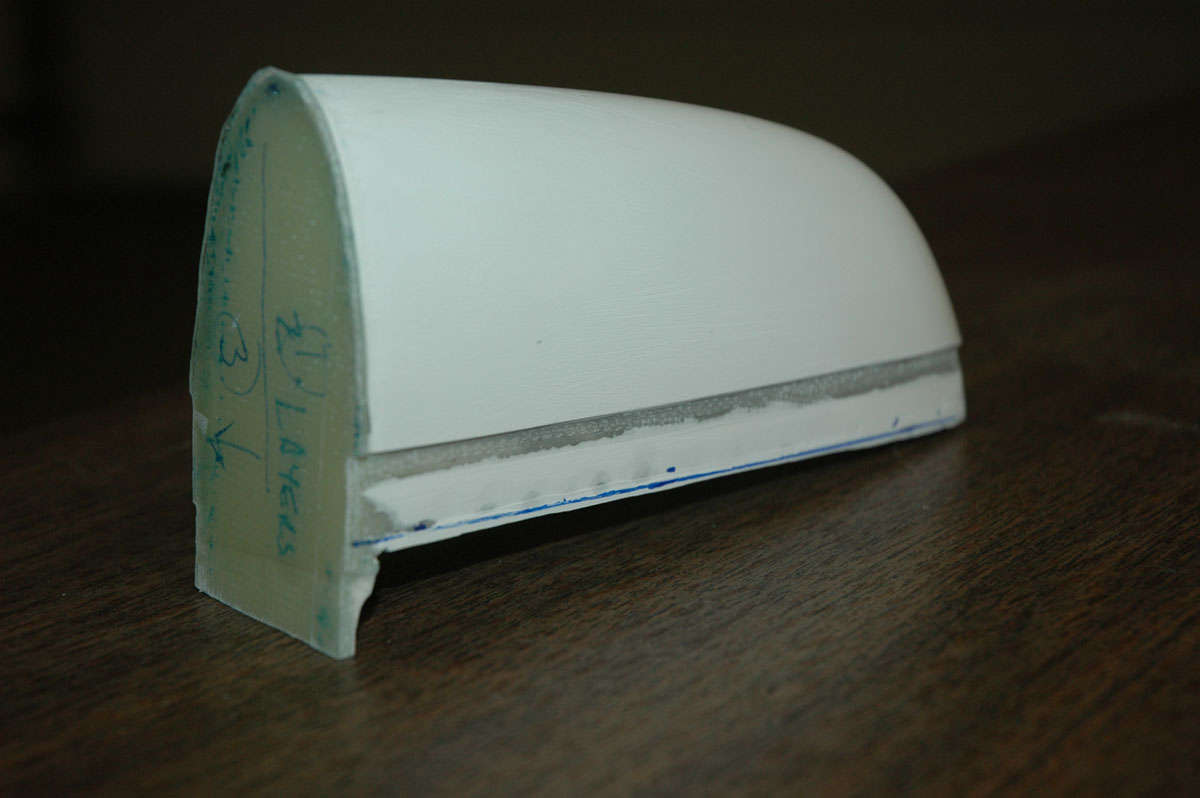
Moving back to the horizontal tips, here I am about to match drill the tips. There were no pre-punched holes here and though the plans call for four rivets on top and bottom here, I decided to match the elevator tip spacing and made just three holes. It will make for easier setting of the nutplates also since there will be a bit more room to work.
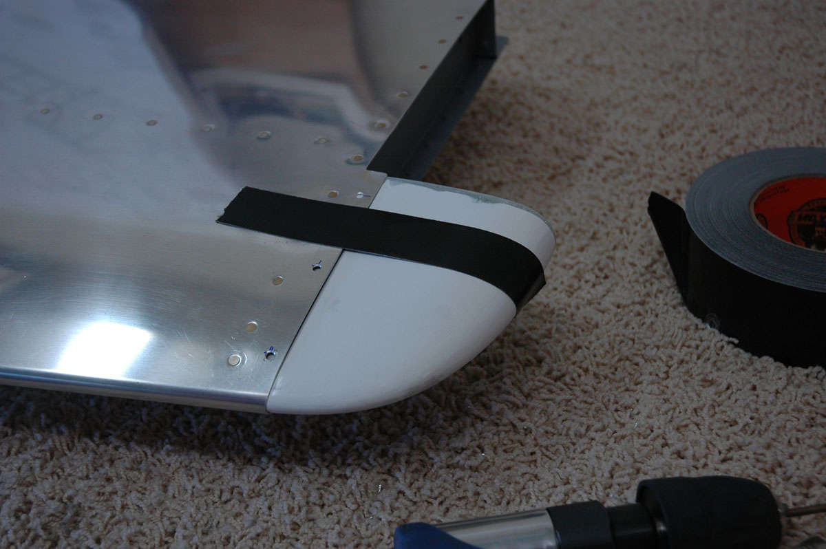
So, I set about to drill the holes for the nutplates. Took a bit to get this process down right. I needed to enlarge the nutplates holes for the NAS1097AD4-4 rivets, which I decided was the best way to set them in. Just a bit of countersinking done with the deburring tool will set the rivets in the fiberglass flush.
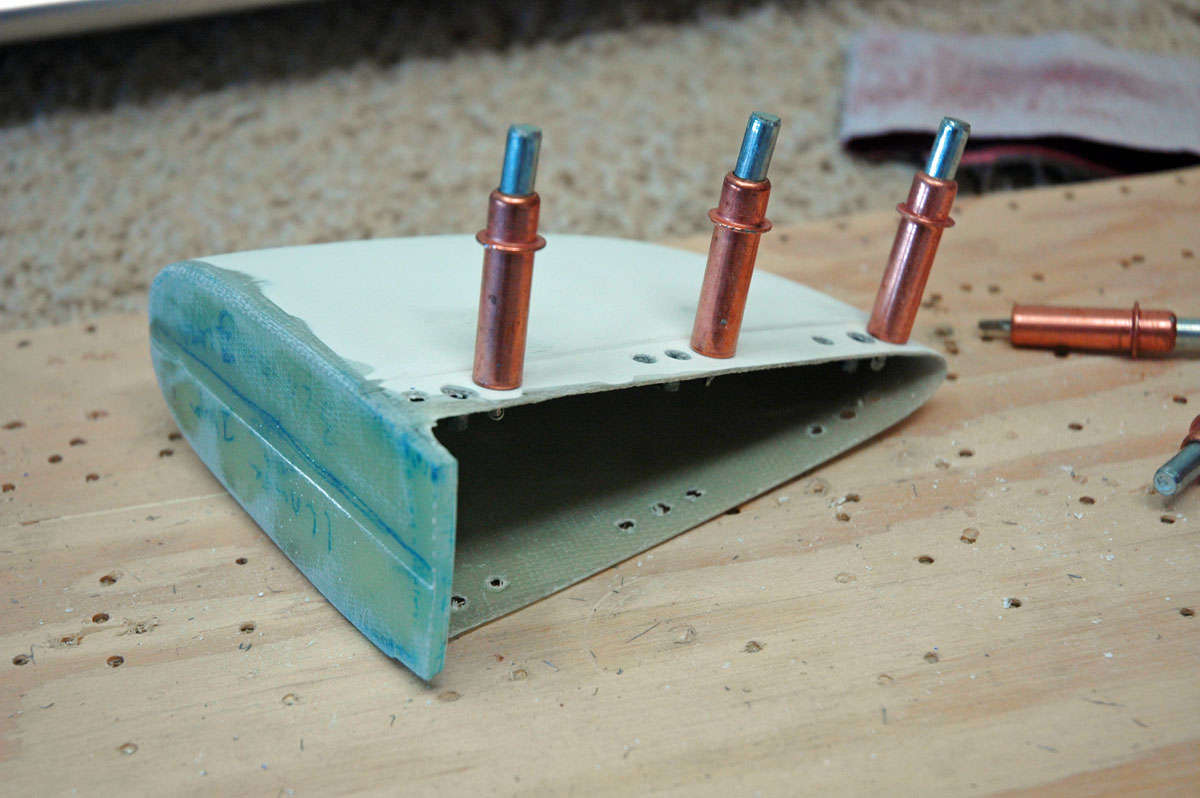
Okay, making some progress here. Seems like this whole fiberglass thing is taking a long time, which it is. But I am in a but of a lull here anyways, waiting for the wings, and it is good to get over this little skill set hurdle. I've found from the little fiberglass work that I've done is not to be afraid to try something. Most fiberglass errors can be readily corrected.
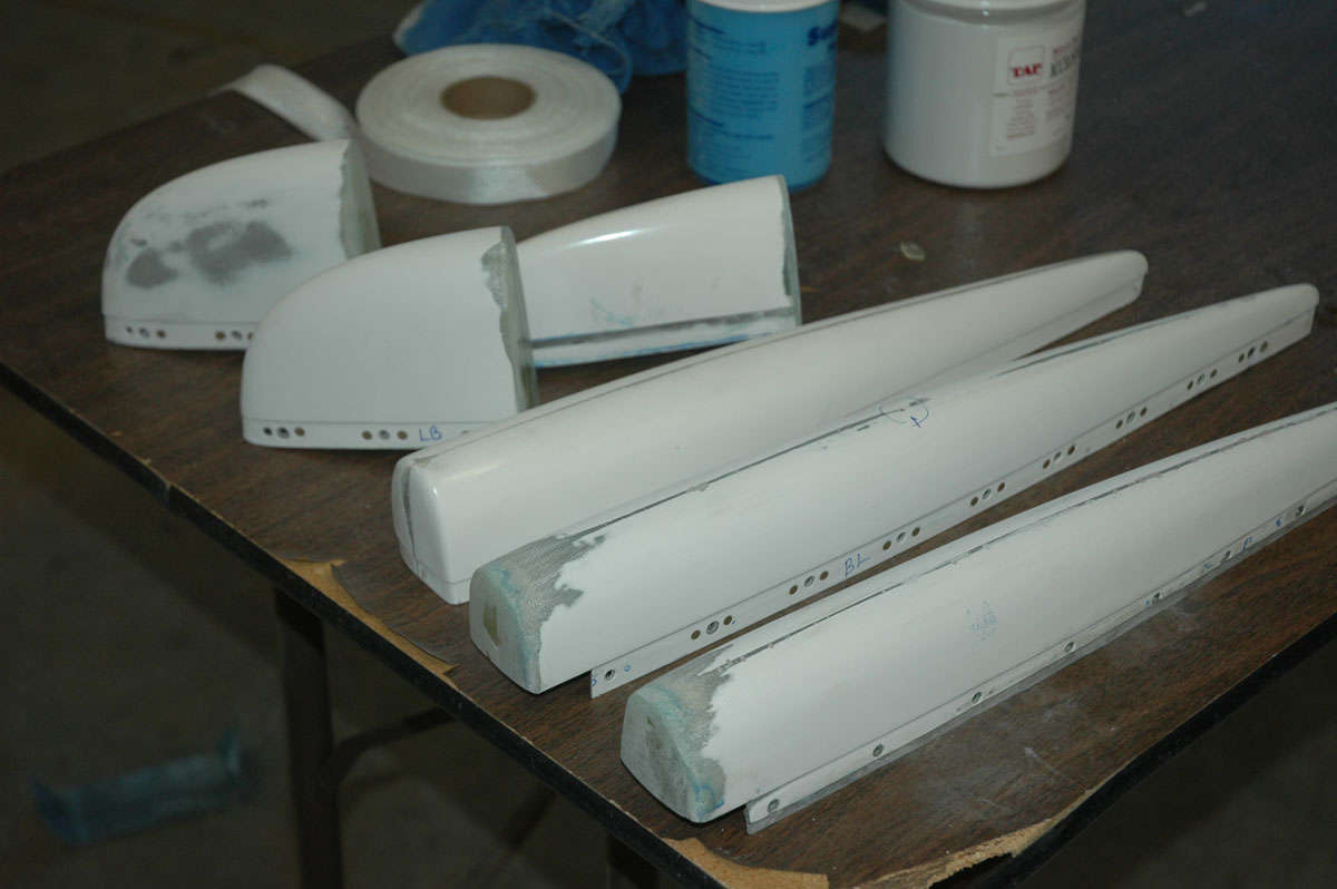
By the way, I am intentionally not doing the rudder bottom tip. Several sites have noted that for the RV-8, the tail wheel mount interferes with the bottom tip, and it needs to be cut down to fit. Thus, that part will be done later. Need to install a position light on that part also, something else that will come later anyways.
So, here I am setting up the holes for the nutplates to be mounted. I set up a template using a nutplate with a screw inserted. I then put the screw into the hole to allow the centering of the nutplate, and then drill with the #31 drill to set up for the riveting.
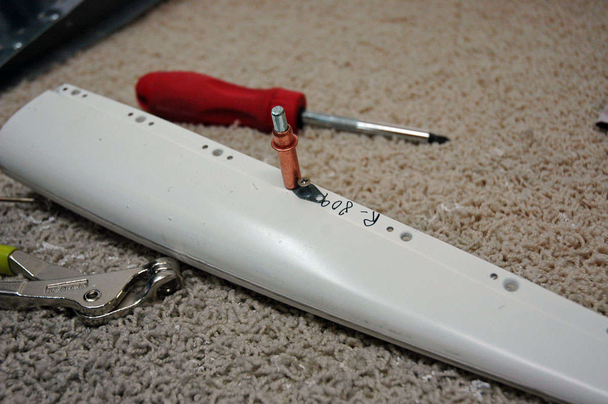
Edge distance was a problem for the forward nutplates, so I used some nutplates, ordered from Aircraft Spruce, that offsets with two rivet holes on the same side of the screw hole. Setting rivets into fiberglass is not the neatest thing but the point is just to provide the mounting point for the screws to hold the tips into place.
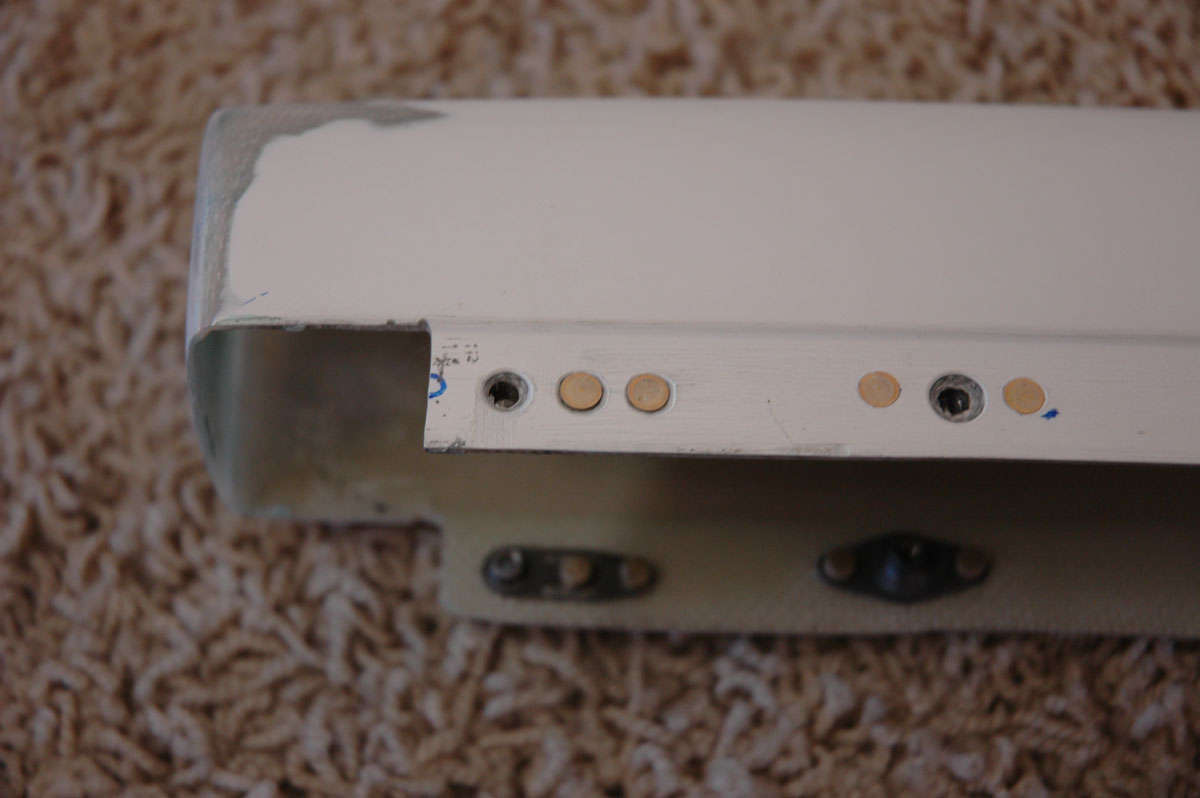
Did some sanding and other finishing work, prepping for the use of fill primer to reveal defects. Got to spray the first coat, revealing not a lot of problems but I fixed those with a bit of thin filler. Let that set up and sanded again.
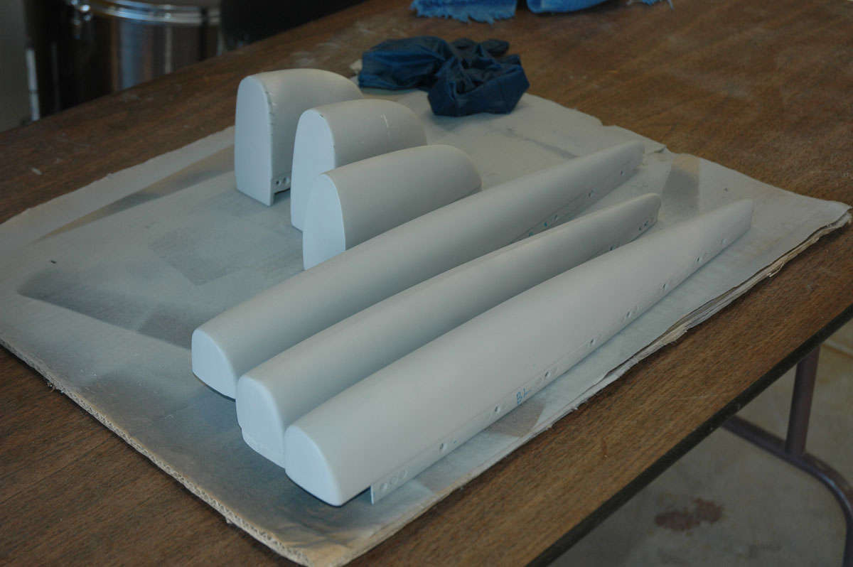
And that's pretty well where I ended last week. I am pretty close to having the tips done. I have a few hitches still to overcome....I need to add some nutplates to the elevators to allow the mounting of washers to add weight to replace lead that I had to file off to get the tips to fit. Some other cosmetic efforts to finish up the effort, all of which I hope to complete in the next week or so. I also want to do a final adjustment to the rudder-vertical stabilizer hinges to set and square up the gap. More to come.
November 29, 2009
Bogged down in tips, what else can I say? After all is said and done, I'm glad that I used nutplates and screws to attach these parts, but it has been an unexpected challenge. Some of it was the nutplates...I worked too hard on them. Another part of the challenge is that the tips did not match up too well, i.e. rudder tip and vertical tip. Height was mismatched, then I compounded it a bit by lowering the river, so to speak, instead of raising the bridge. Specifically, as noted earlier, I lowered the vertical tip a bit instead of just raising the rudder tip a bit. I ended up lowering it too much and then, oh well...on to my travails.
I started by trying to fill in the area on the forward part of the vertical tip with some epoxy and microbubbles. Okay, then.
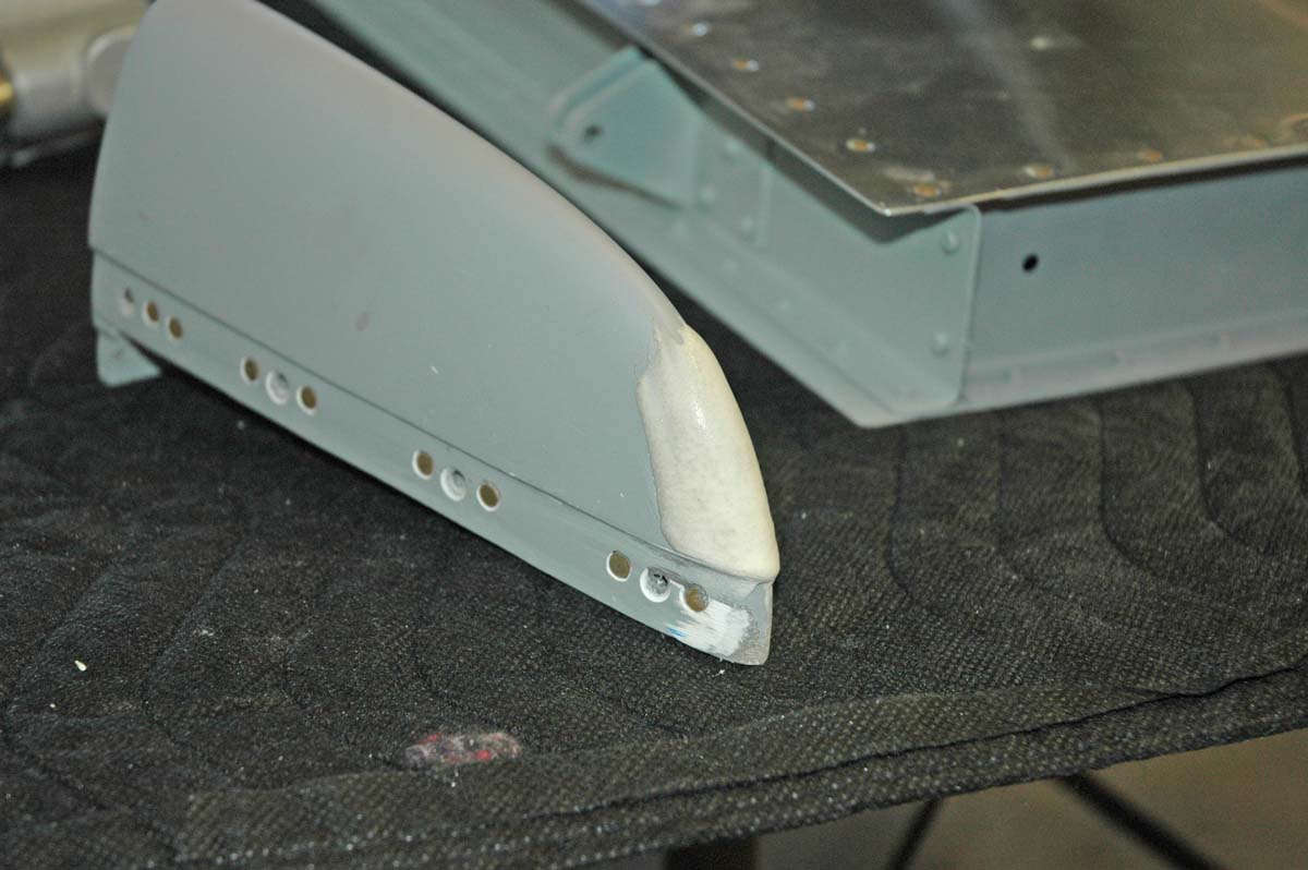
Another view with some masking tape placed to help me sand a bit.
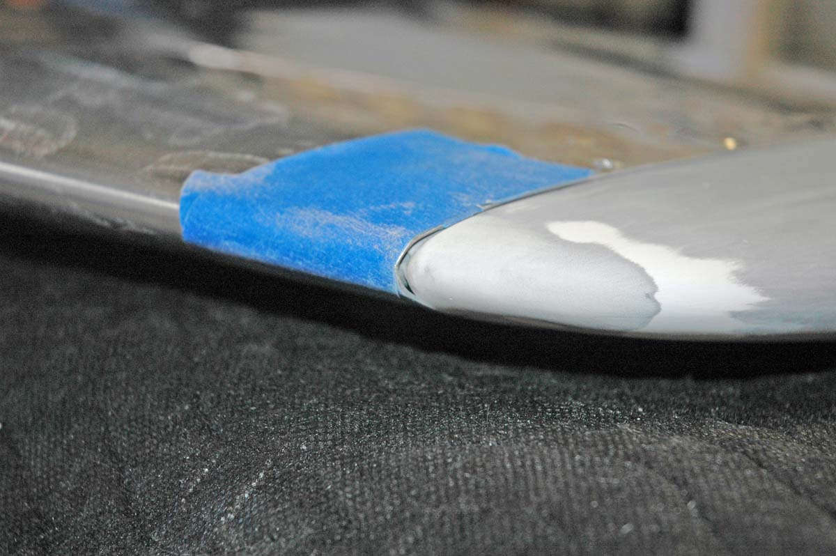
Not happy with joint of the rudder tip either, I used some packing tape to protect the aluminum and filled this area a bit, trying to close the misfitting gap a bit.
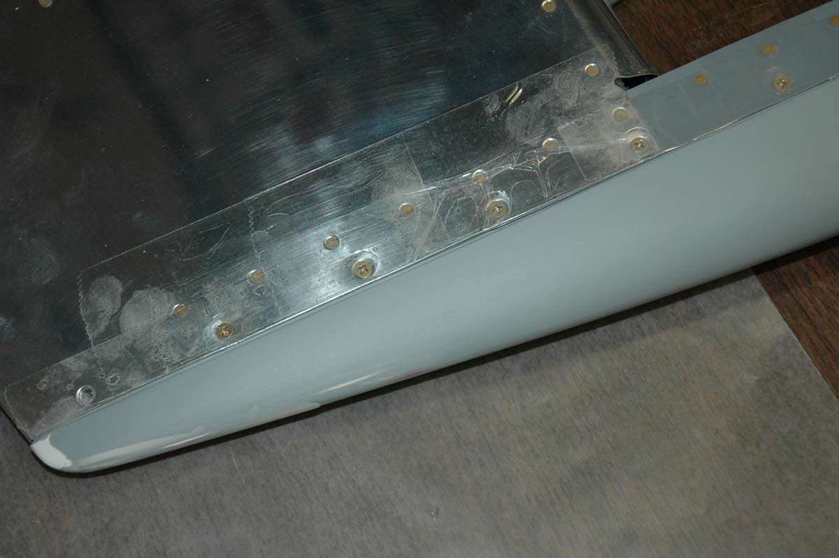
Then I figured out I lowered the vertical tip a bit too much and had to raise the top contour a bit. Slathered on some more microbubbles. So, why do they call it microbubbles, anyways?
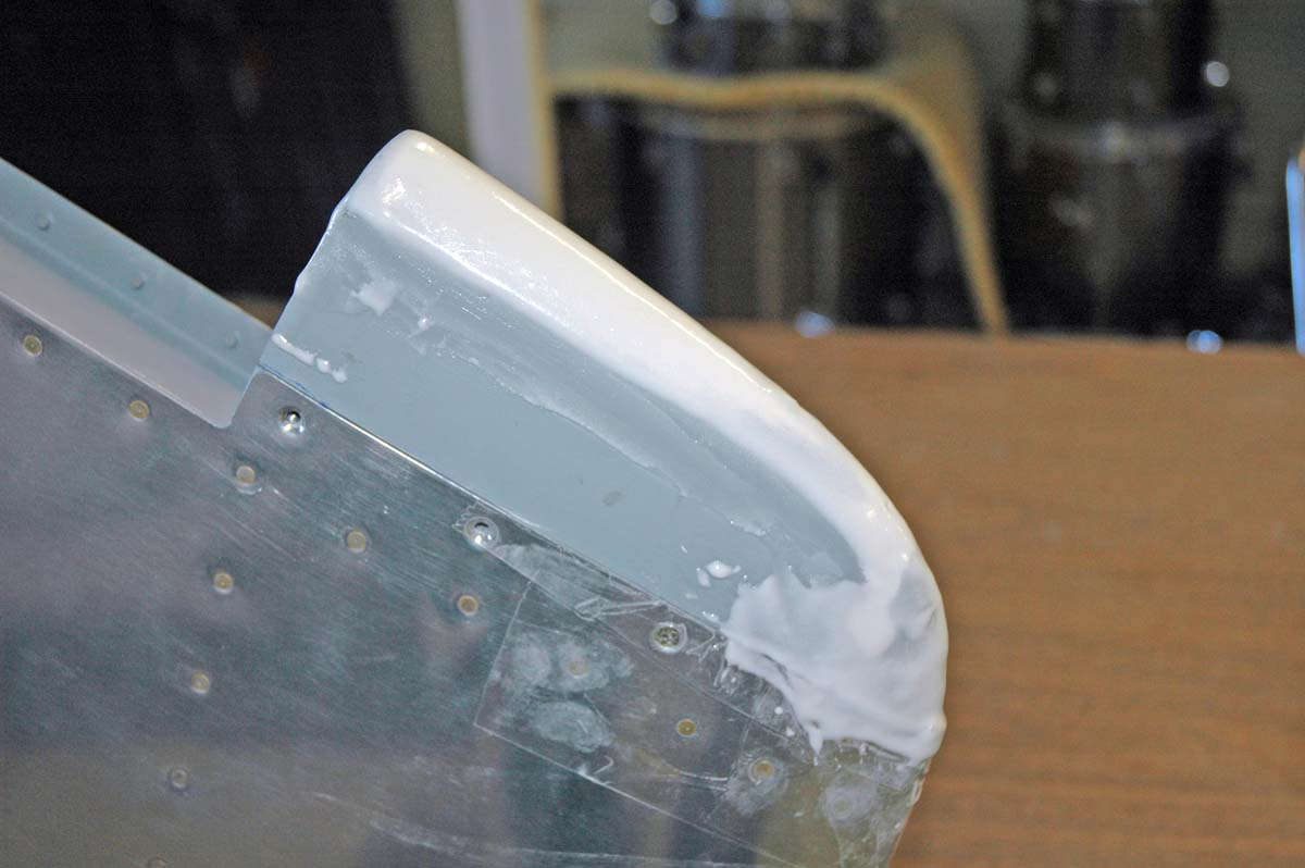
Another view...it was getting ugly out there.
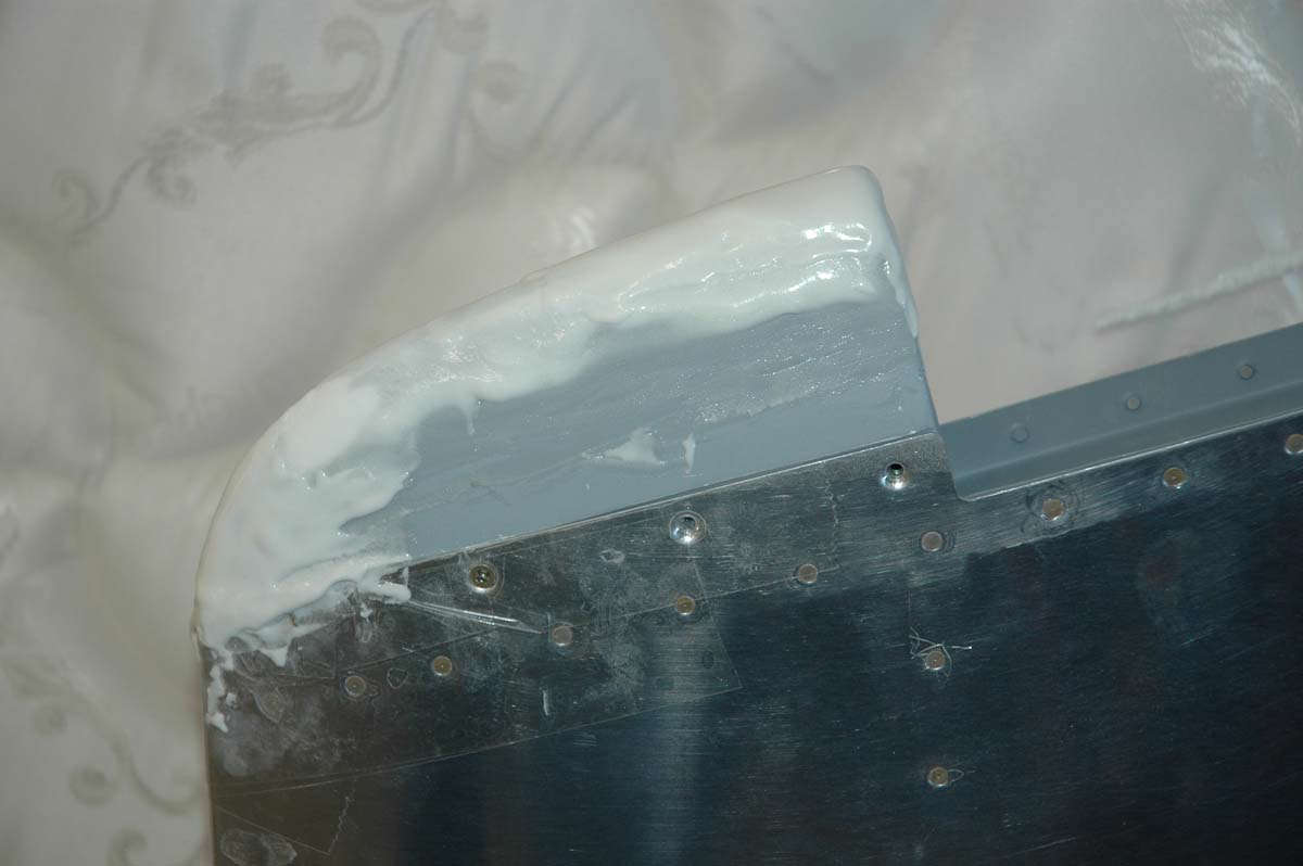
Meanwhile, I was doing some clean up work on the other tips, using a bit of glazing the rivets a bit as they don't set so well in fiberglass...not a neat countersink, as it were.
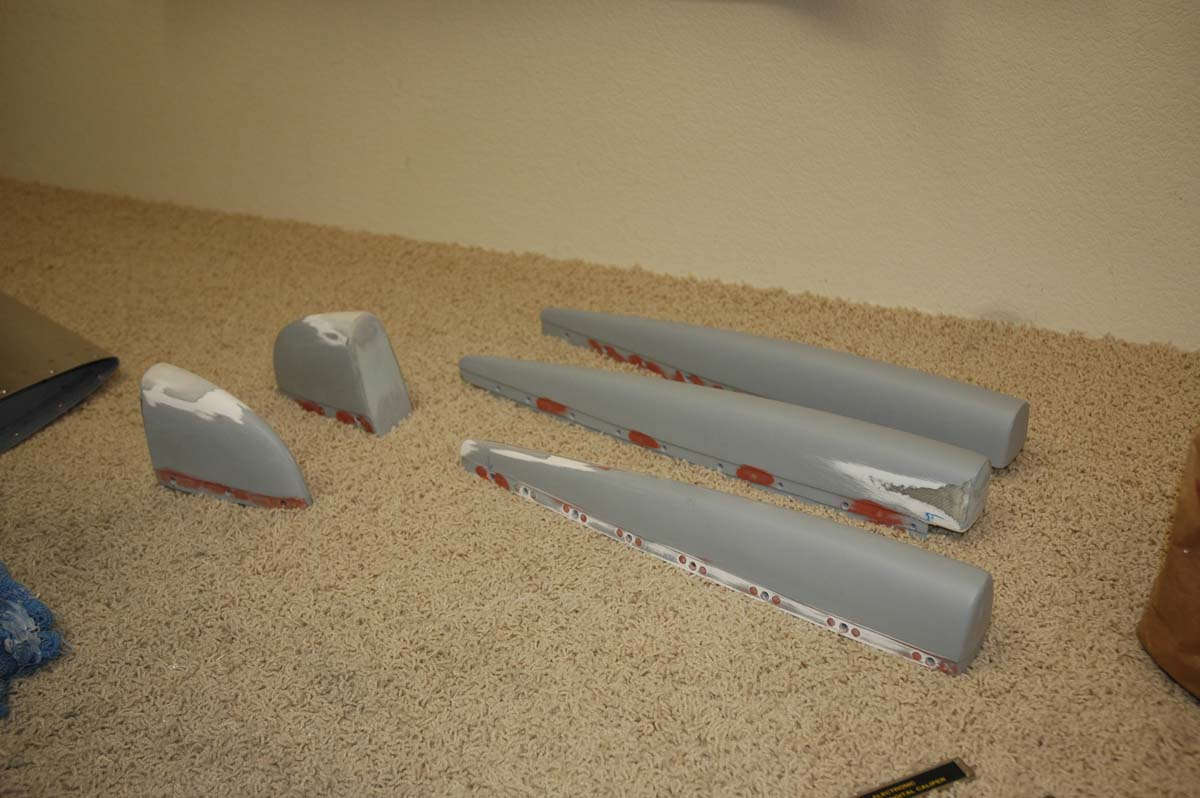
Kind of the raw version here, before cleanup. This is the elevator tip with the aluminum doubler, something that has caused me continual problems. Ugh. The problem was that the epoxy I used to bond the aluminum strip to the fiberglass can't take too much direct pressure before it gives way. Solved that problem by setting some rivets to hold the aluminum strip to the fiberglass. That, along with the epoxy, should beef it up enough. So, now we have the nutplates riveted to the aluminum strip that is epoxied and riveted to the fiberglass. I was (am) a hair's breadth from tossing the part and starting over with it, but we shall yet see. It might work out.
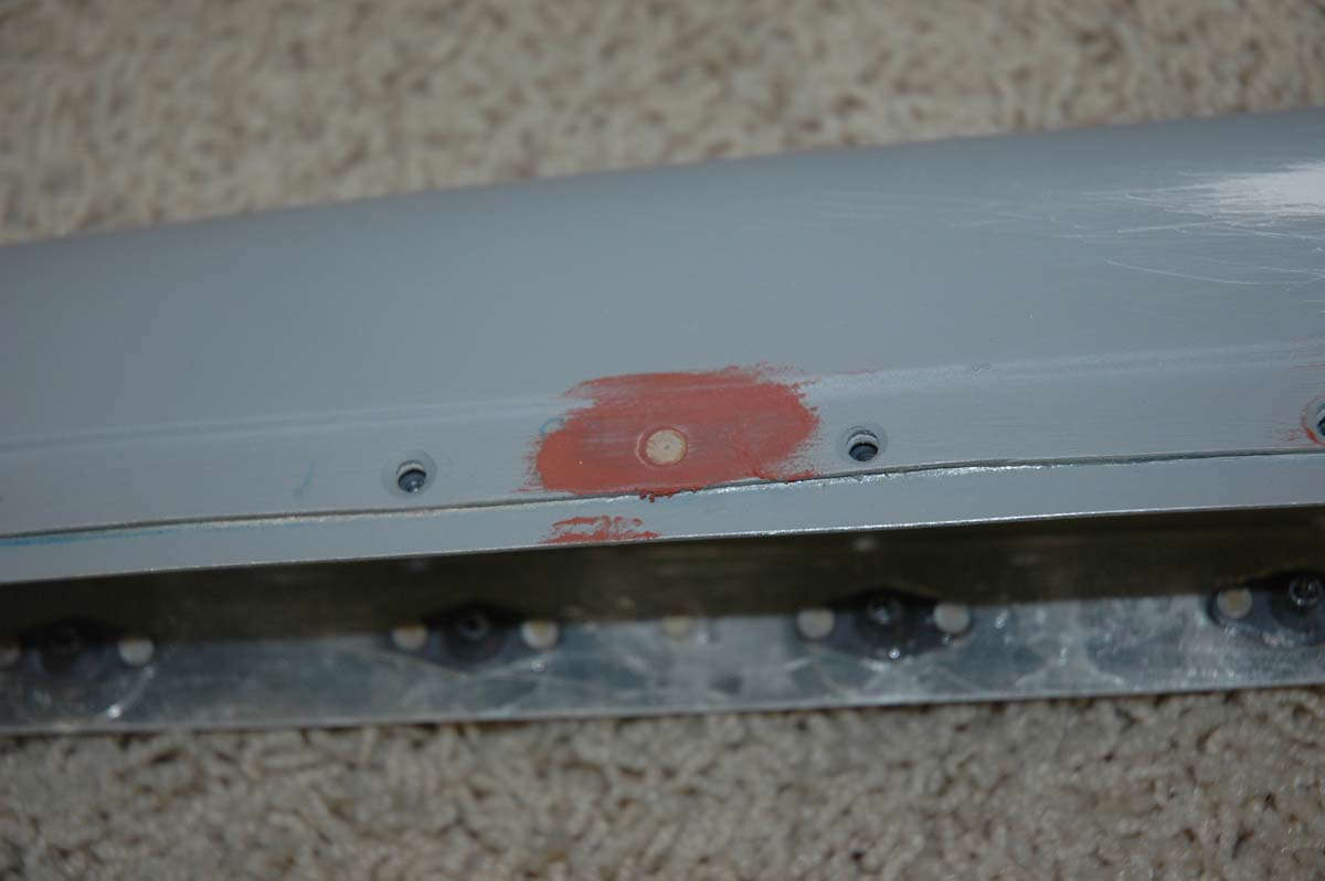
Back to the vertical tip, it's looking better here but when I matched it up with the rudder tip, the rudder tip was wider and didn't flow from the vertical tip. Had to reshape the vertical tip a bit, adding some more microbubbles stuff and more sanding. Kind of 'dig a hole and fill it with microbubble.' Understand this work was done over several days as you need to let this concoction set up overnight.
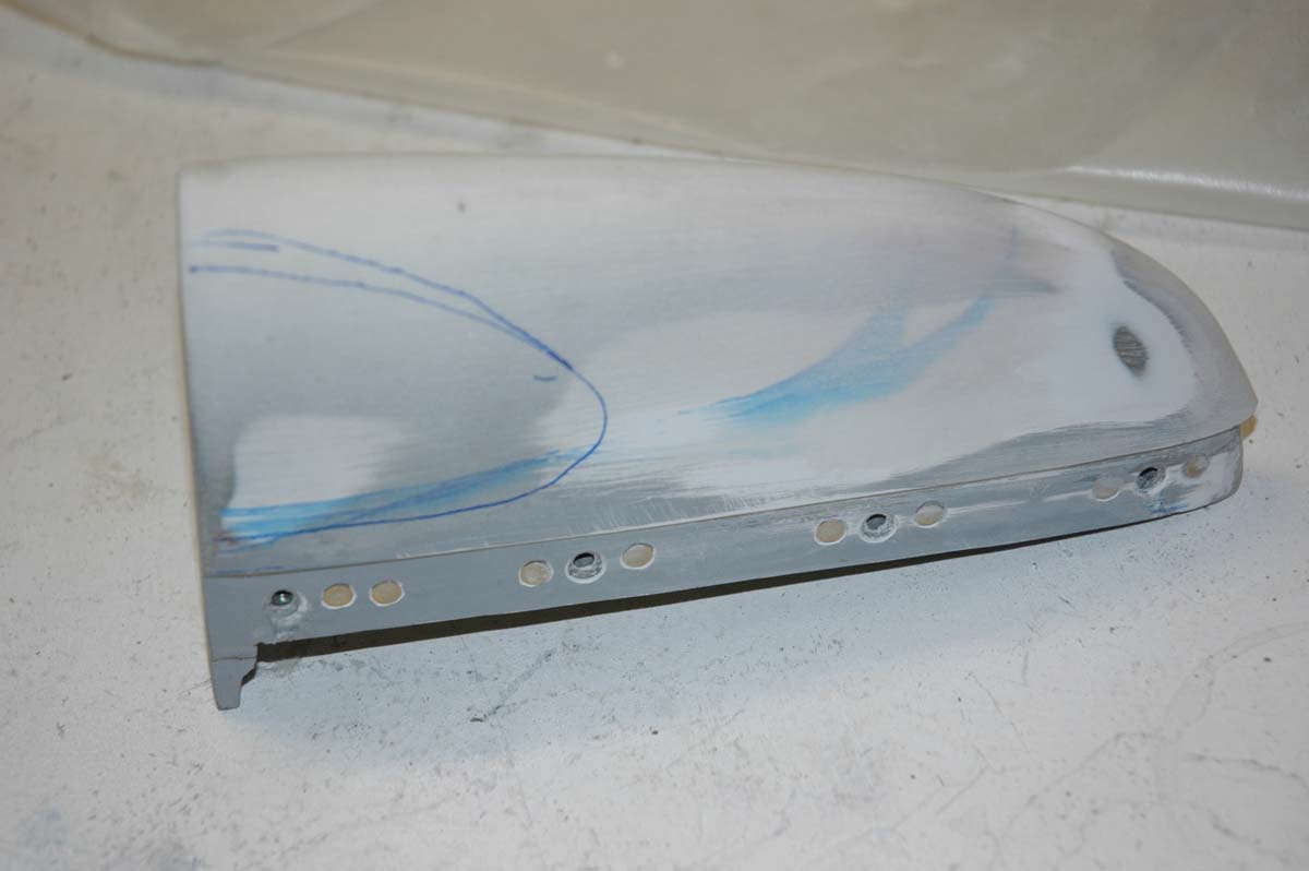
Getting close to being relatively happy with these tips. Just a bit more finish work and a final coat of sandable primer to finish them up.
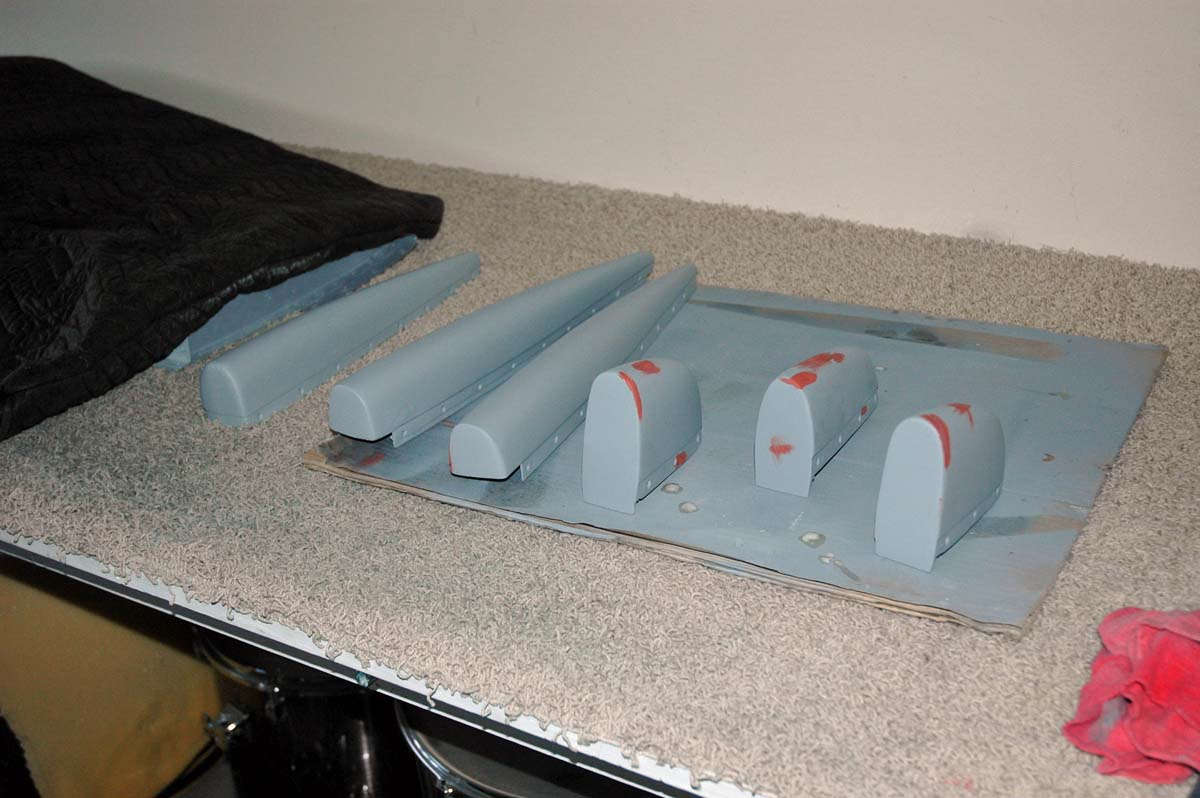
Taking a tip from Van's RV Forum's Rick6A, I used his method of adjusting the elevator counterweight. A K1000-4 nutplate is mounted to the small machining hole located just behind the counterweight after the hole is drilled out to 1/4 inch. Then, AN910-4 washers (the big boys) can be added to an AN4-4A bolt (on the other side of the assembly from this photo) so fine adjustments can be made to the counterweight weight. I did a static balance on the right elevator using this method, and can easily adjust it later after paint is added to the elevator.
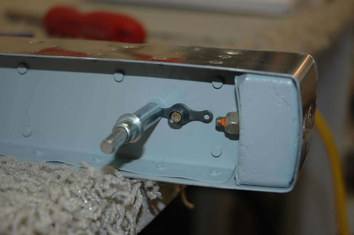
Here's a view from the other side with the bolt and washers installed. By the way, ignore the incorrect orange torque seal application. The torque seal should be applied to the nut-washer-skin surface, not the threads. Everyone knows that, right?
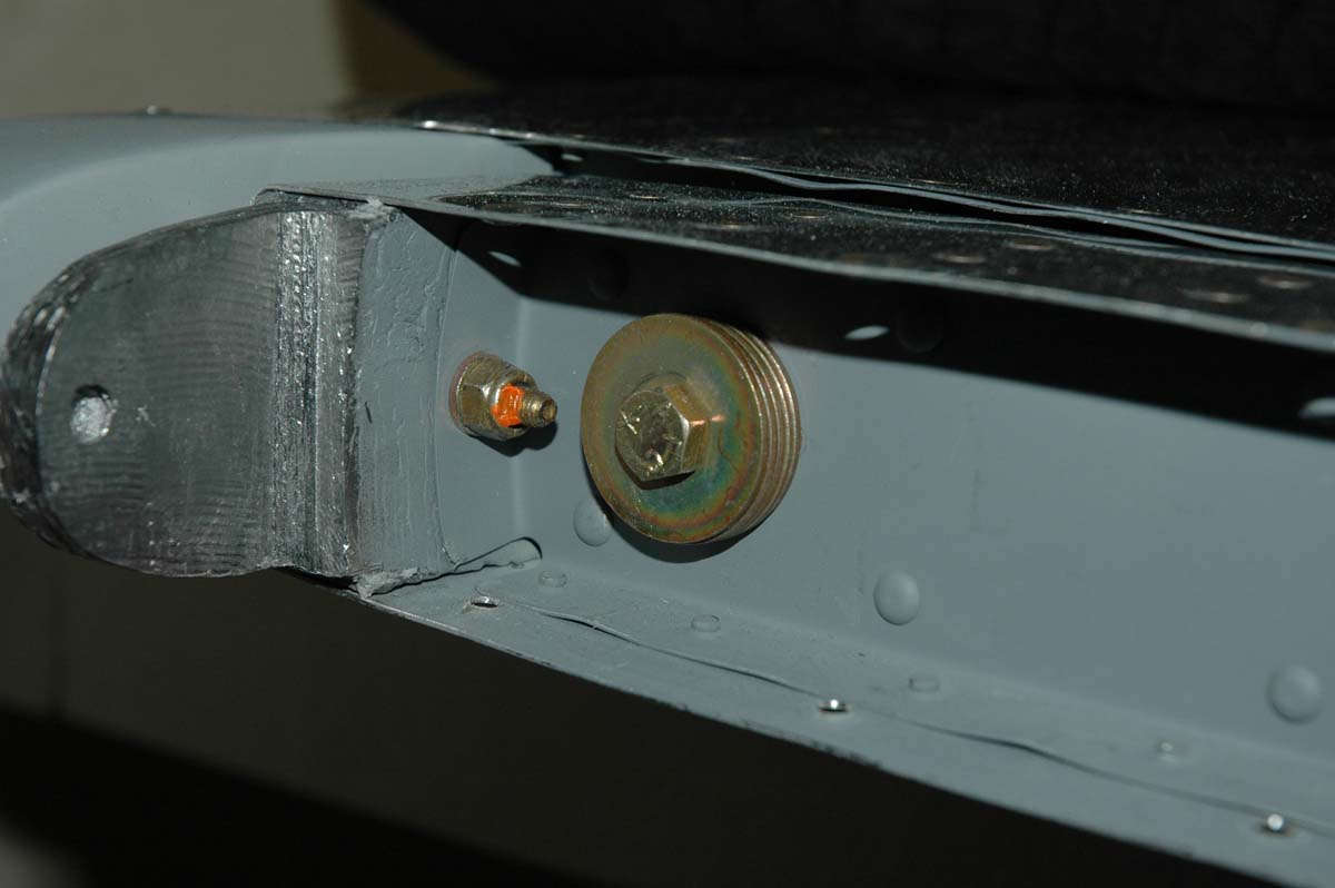
A note from experience: the written instructions don't mention it, and there is but a very small note on the plans (Drawing 5, E-714 Trim Detail) that indicate that only the counterweight for the right elevator is trimmed down. The left elevator counterweight is left untrimmed to account for the weight of the trim tab servo. It would have been good if I had known this before I trimmed the left elevator counterweight and installed it in the elevator. I then had hoped my little washer trick would work here also, but I need about 14 ounces of weight. Each washer weighs, I'd guess, about 0.4 ounces, so that is like, maybe 34 washers. Hmmm. Plan B is to order another E-614 rudder counterweight and trim it down to install just behind the E-714 counterweight using AN4 bolts and AN365 nuts. Nuts.
So, that's where it's at. I need to install that cut down E-614 weight, do a bit more finish work on the tips, and then these two major subassemblies should be completely completed. Wings are scheduled to be here next week, so when I order the E-614 weight (today) I'll also order a few other parts....wing conduit for wiring, some hardware, and maybe some Pro-Seal for someday fuel tanks.
Here is the rudder and vertical stabilizer in that completely complete state, or just about. Always just about.
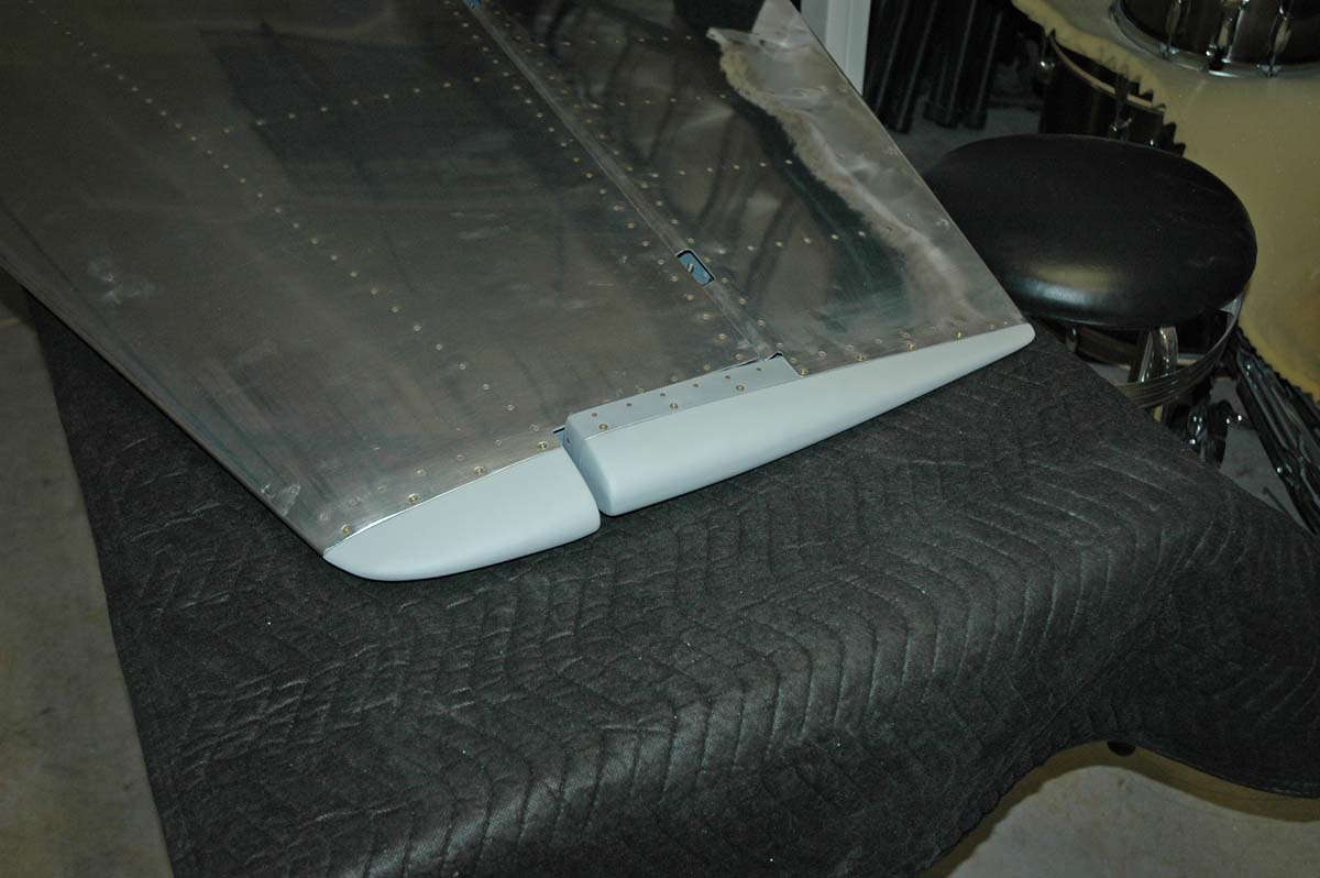
And one more.
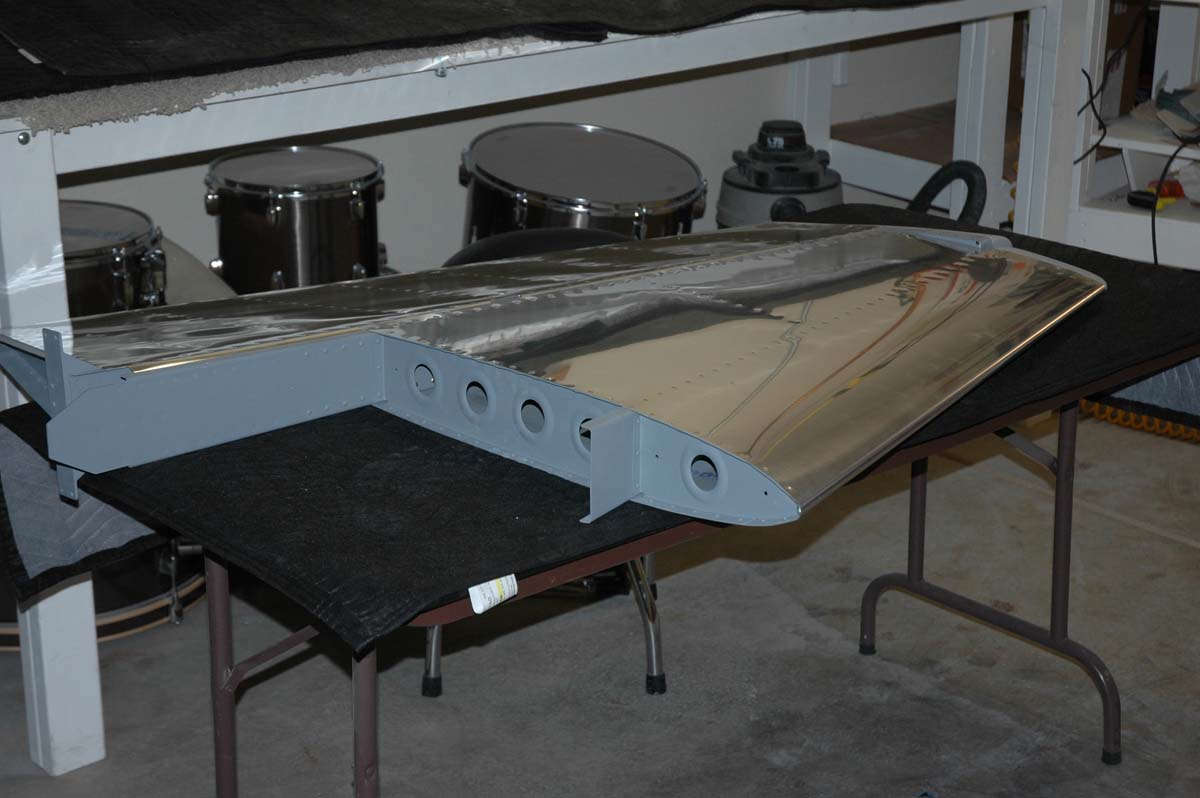
December 7, 2009
Pearl Harbor Day, and don't you forget it.
Well, after eleven months of work, I finally finished the empennage. Doing the fiberglass tips was a good thing, but the finishing process caused the whole empennage process to sort of end with a whimper. I can't really point at anything significant done this past month except for a couple of pieces of fiberglass screwed onto the ends of the different parts. Big deal? Well, it works for me and I'm pretty happy with how it all turned out. Maybe a bit more work to do in prep before paint many years from now, but that will be then. This is now.
At the end of our last episode, I had ordered an E-614 counterweight from Vans, along with some associated hardware. It showed up a few days later, and I took the 24 ounce weight to one of my expert advisers (Mr. Greg) who happens to have a band saw just in front of him. We cut this thing down to about 16 ounces, leaving two ounces to play with with my file. Which I did. Here is the weight at about 14 or 15 ounces.
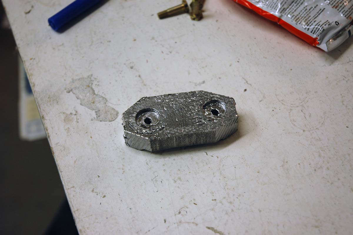
And here is where it is going to go, bolted in just behind the normal counterweight that should have done the job if I had done a better job of reading the plans.
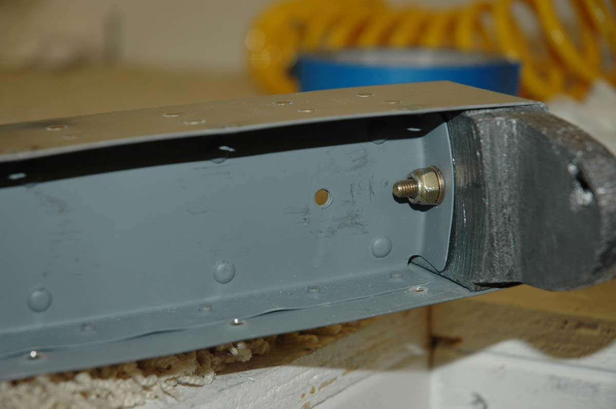
And here the deed is done. This thing is mounted on the side opposite of the elevator, so if it happens to come loose it will just rattle around in the fiberglass tip. It's torqued down "right proper" but it will no doubt be an often checked item. Good thing I made the tips removable, eh?
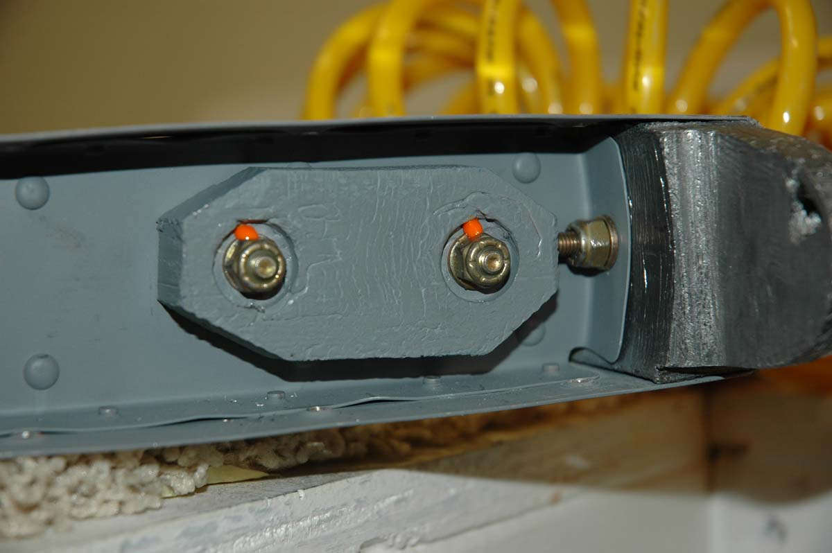
So, when all is said and done, the fiberglass tips are screwed down. It looks better when it's done, and it doesn't look like it should have been that hard. The trials and tribulations of the learning curve.
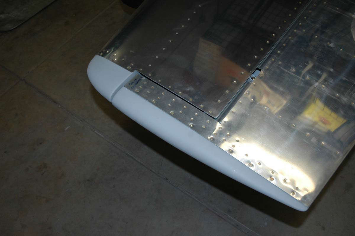
I admired my handiwork for about ten minutes or so. Looks pretty cool.
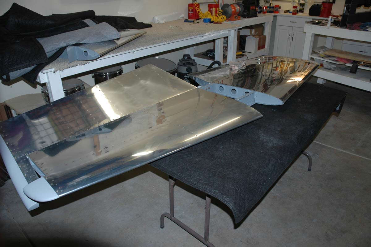
But, there was no one around to admire it with me and, even if there was, they probably would have just been polite anyways. So, I implemented Storage Plan A, which was to attach the elevator to the horizontal, store it from my little hanging shelf attached to the garage ceiling, and then store the rudder and vertical stabilizer stacked carefully above that. I thought about that for a few minutes and thought about just how many ways of something going wrong with that plan.
In the end, I carefully wrapped the horizontal stabilizer and hung it my little rack. Then, I stacked the elevators carefully above that.
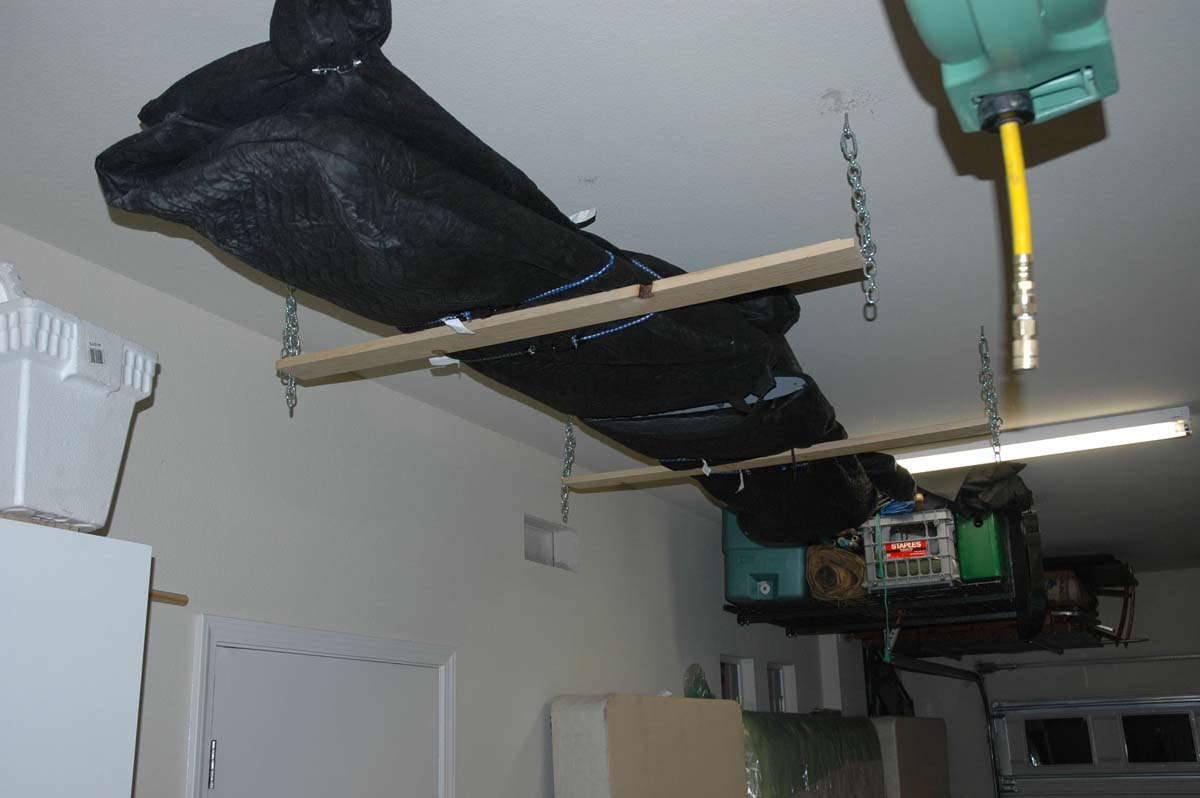
I looked around on my garage wall and found two places to hang the rudder and vertical stabilizer from.
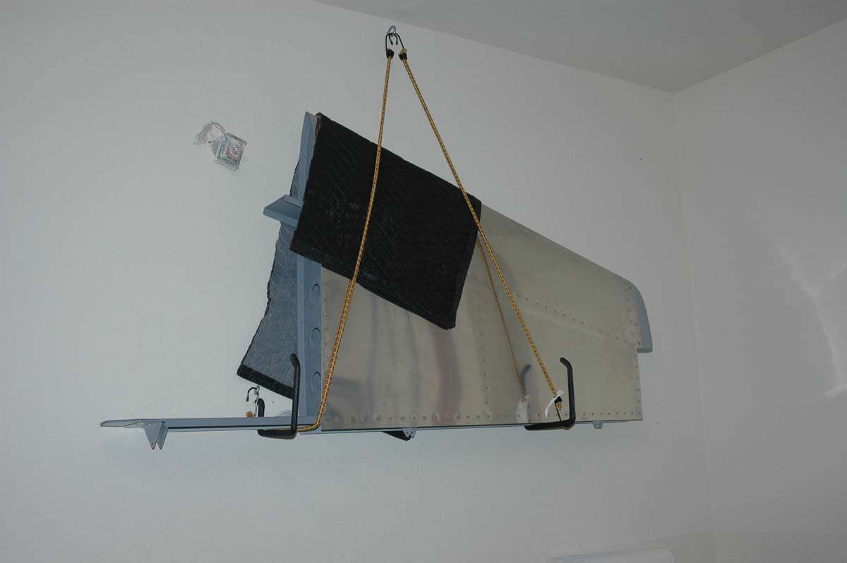
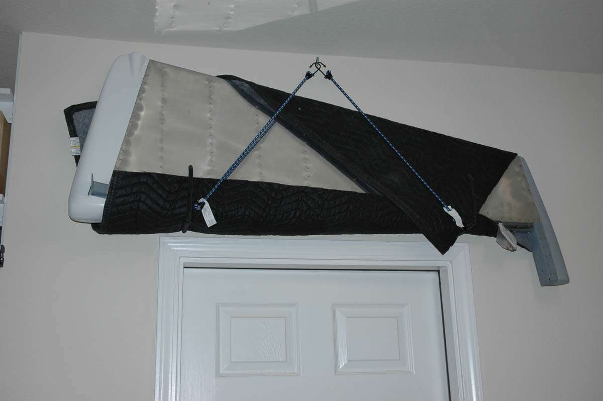
And there they shall sit for probably five years, maybe less if I get rich or have much more time to devote to building this airplane. They will come down next year some time, as my EAA Technical Counselor suggested we combine the final inspection of the empennage with the wing inspection when the wing is pretty much assembled except for the bottom skin. And, maybe before that if need be. The main thing is that it is done and I can now move on to the wings. The wing kit, by the way, should arrive this week, so stand by for more. Don't expect to get too far into the wing until January, but maybe inventory and organize for the next few weeks. Should be fun.
December 31, 2009
As I end my first year of building and start my second, I'll take a few moments to reflect back and look forward. I started 2009 with the delivery of the empannage kit, and it ended up taking the better part of the year putting that kit together. I ordered the slow build wing kit in mid-September, thinking I'd be ahead of the game but am still waiting for delivery, now expected in mid-January. But, for now, a few observations:
Things I expected:
Things I didn't expect:
A few tips based on my limited experience:
On to the wings.