|
The Project in Chronological Order From Day One Year Five: 2013 |
January 1, 2013
Year five of the build starts with most of the actual structure completed. Working on electrical for the most part now, and still need to finalize the fuel and brake plumbing in the fuselage. So, mostly systems work for the forseeable future.
January 20, 2013
I need to play some catch-up here since I have not updated in over a month. Not that I haven't been working on the plane but it has been a bit disjointed with Christmas and other stuff going on.
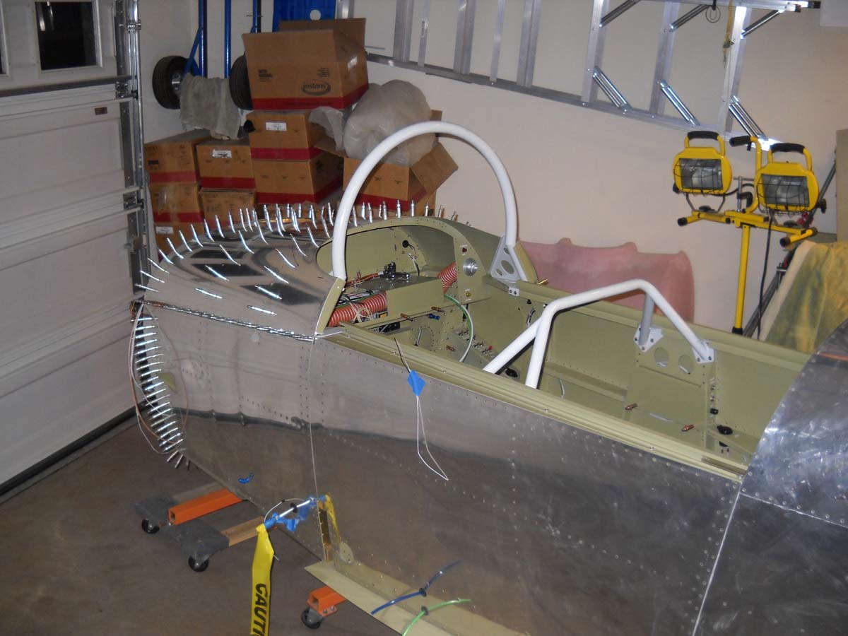
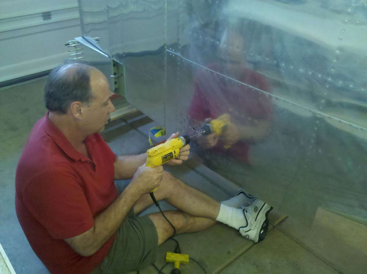
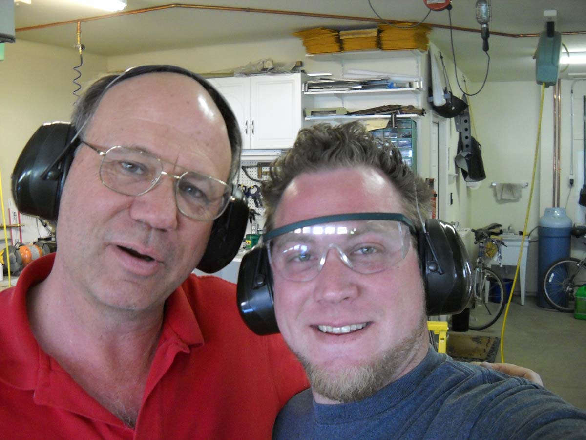
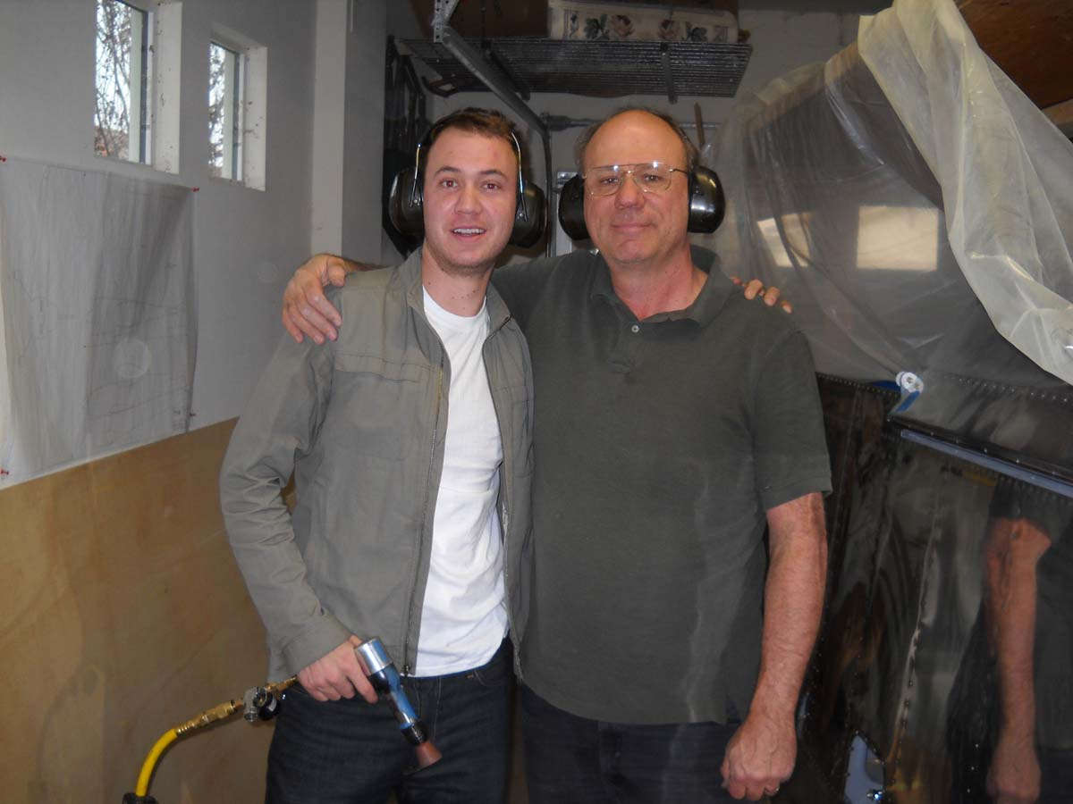
Start off with a picture of the wing riveting team taken when the wings were finished up in mid-December. My riveting partner (that would be Nathan, one of my three favorite sons) has since emigrated to Quebec, Canada, where it is usually about fifty degrees colder every day than Sacramento, at least in the winter. But on the good side, it is a wet, snowy, windy cold.
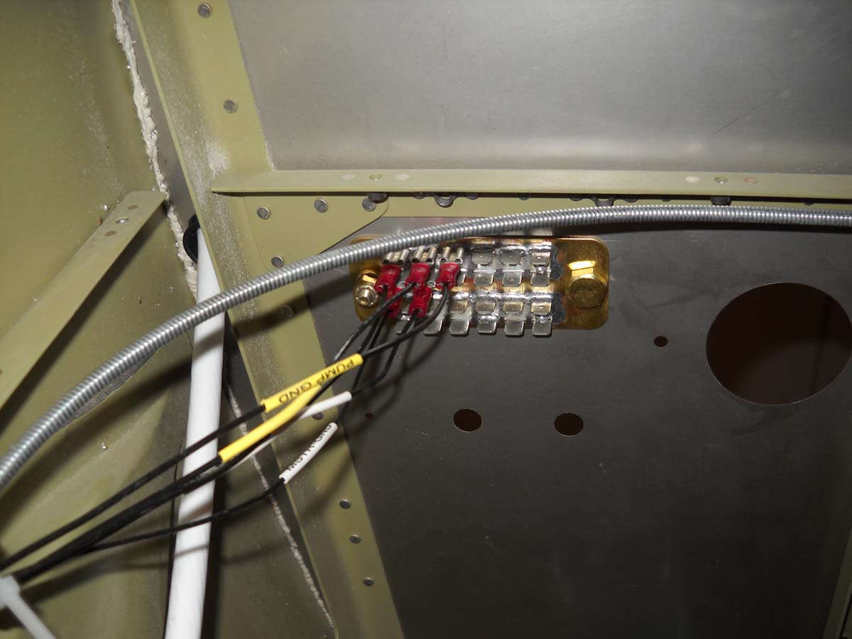
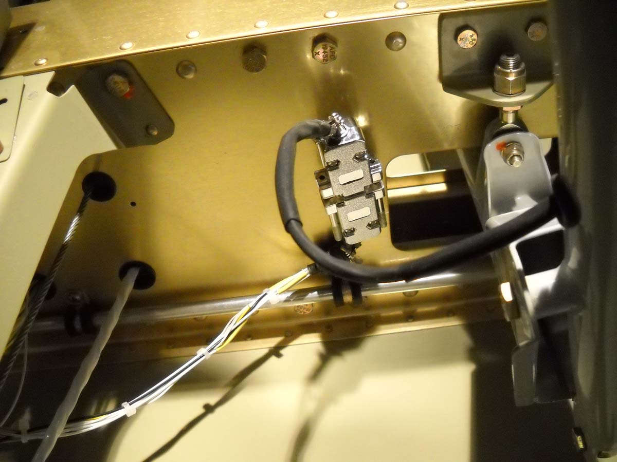
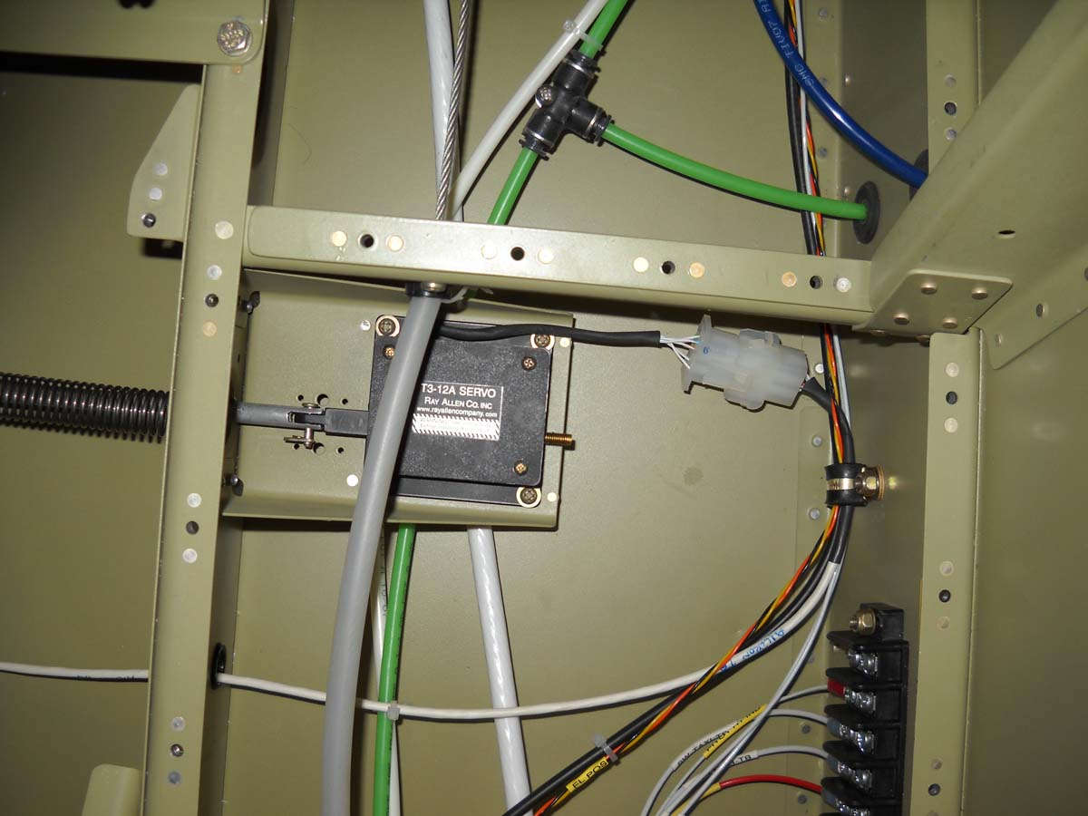
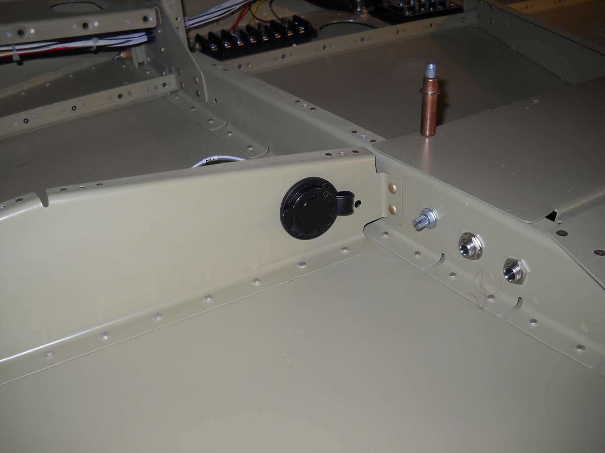
Part of the electrical installation is this 24 tab grounding point from B&C that is mounted on the aft side of the firewall on the left side (looking forward). Most of the electrical grounds will be routed right to this point.
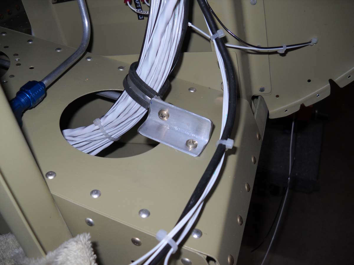
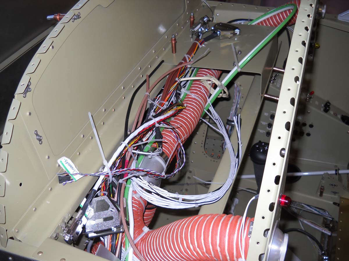
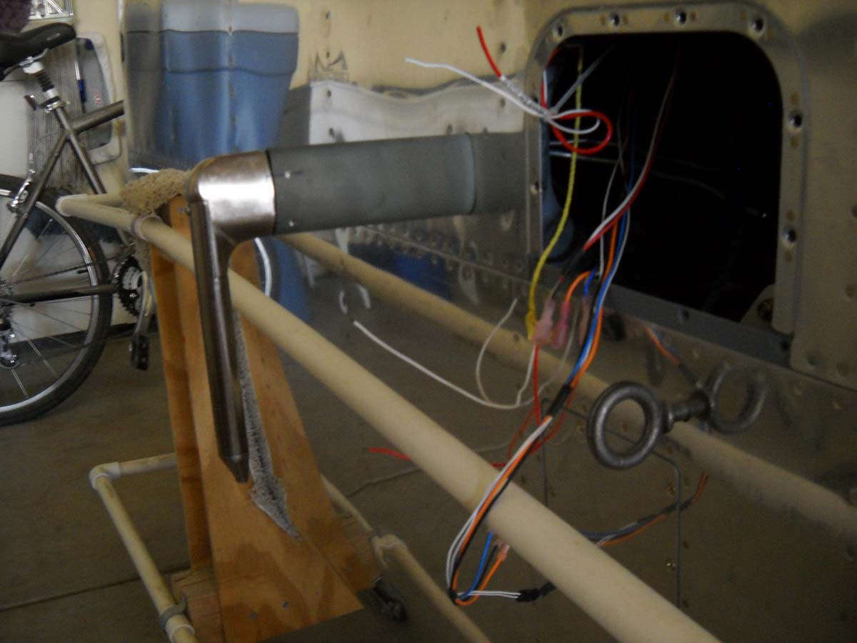
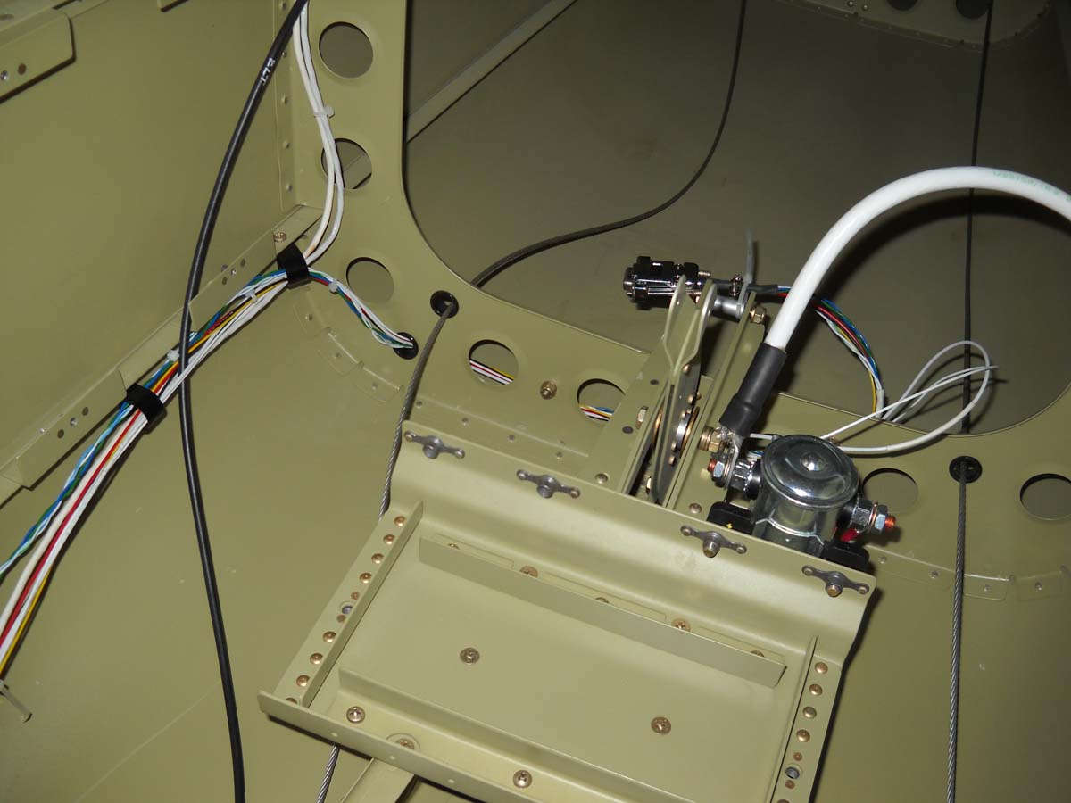
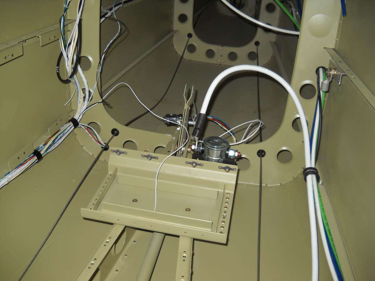
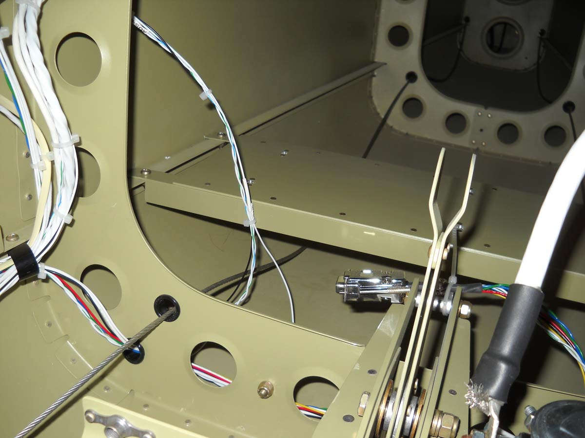
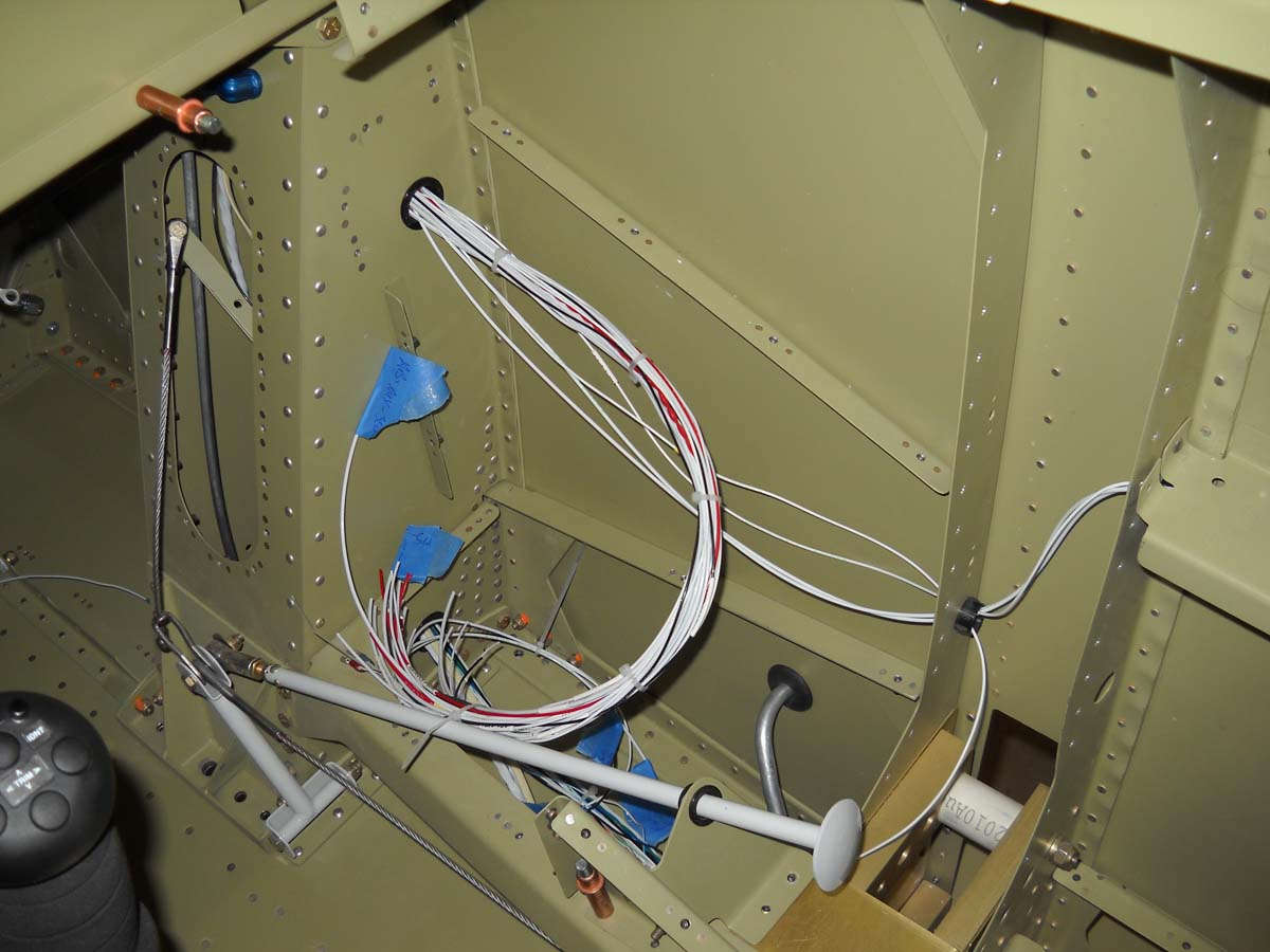
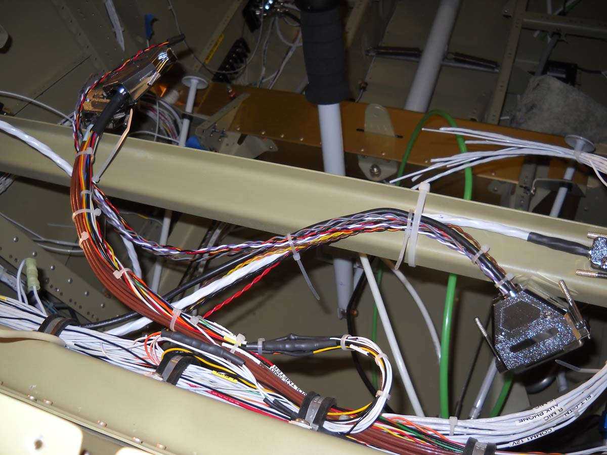
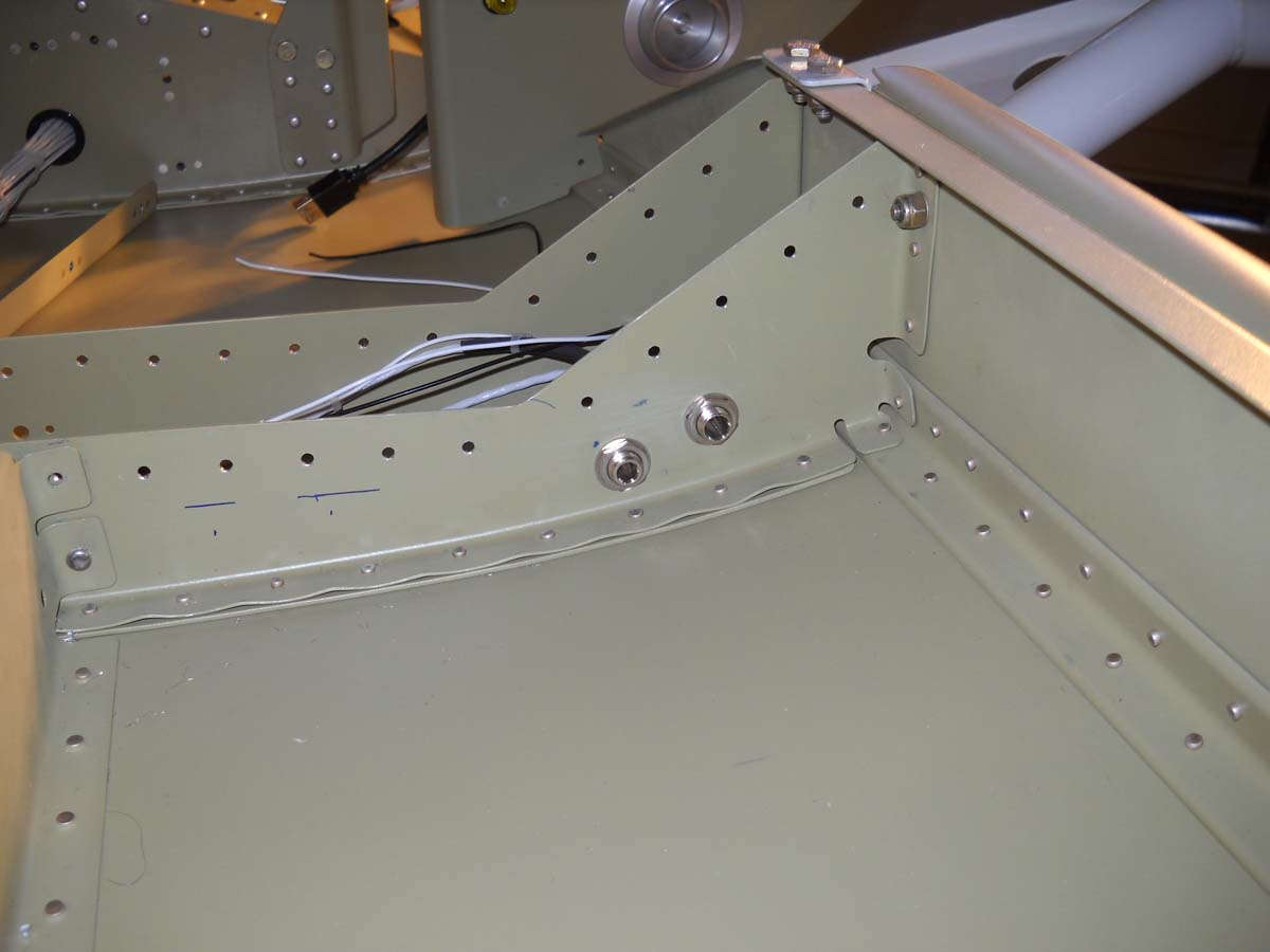
I spent some time working on the routing of the wiring harness that will be attached to the elevator autopilot servo. It needs to be kept clear of the elevator push rod (not installed in this view) and running it behind the bulkhead and under the pushrod and then back to where the servo is mounted seemed to be the best way. Which is what I did.
And, here will be the grounding tab for the battery some day. Basically, I riveted a piece of angle to the longeron (after the paint was scuffed off). This is located adjacent to the battery tray on the left side of the fuselage.

I spent quite a bit of time researching how to have the stick grip wires exit the front stick and, after due consideration, came up with this: a 3/8 inch hole drilled on the right side of the stick near the bottom, with a 9/32 rubber grommet (from Home Depot) inserted for edge protection. This size worked perfectly for the nine wires that come from the stick grip. This view was taken with the fuselage rotated on its left side.
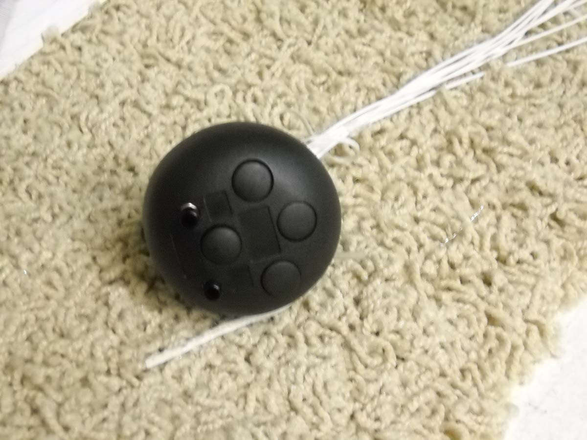
And, here is the stick grip with the wires soldered into the gip, courtesy of someone who knows well how to solder (thanks Duc!) There is no way I could get all those little wires soldered to all those tiny terminals without ending up with a massive globule of solder all over everything.
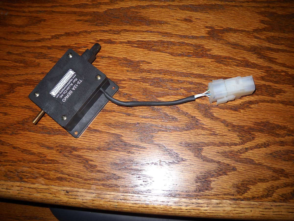
And, here is the aileron trim servo with a AMP connector added. It is ready for installation and final wiring at this point.
Okay, all caught up now to where I was in early January. I've done quite a bit of work since then which I will add here shortly.
February 3, 2013
Back at it, or rather pushing along a bit at a time. Continuing working on the electrical system, planning and installing wiring runs and figuring out where some of the black boxes will go.
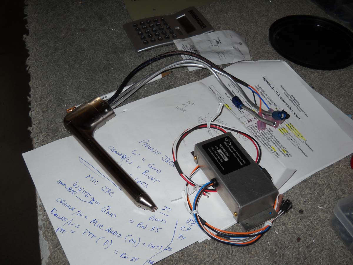
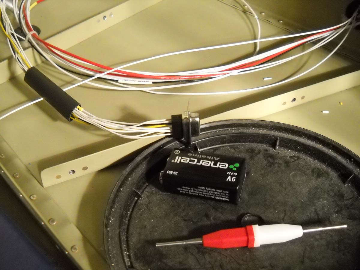
I completed the wiring for the front stick, that bundle consisting of nine wires that control the trim, the push to talk button, a control wheel steering button for the autopilot, and an ident function for the transponder. I used a d-sub connector to join it to the wiring already installed in the control stick. Here I am checking the continuity of the wires and trying to establish the correct hookup for the elevator trim.
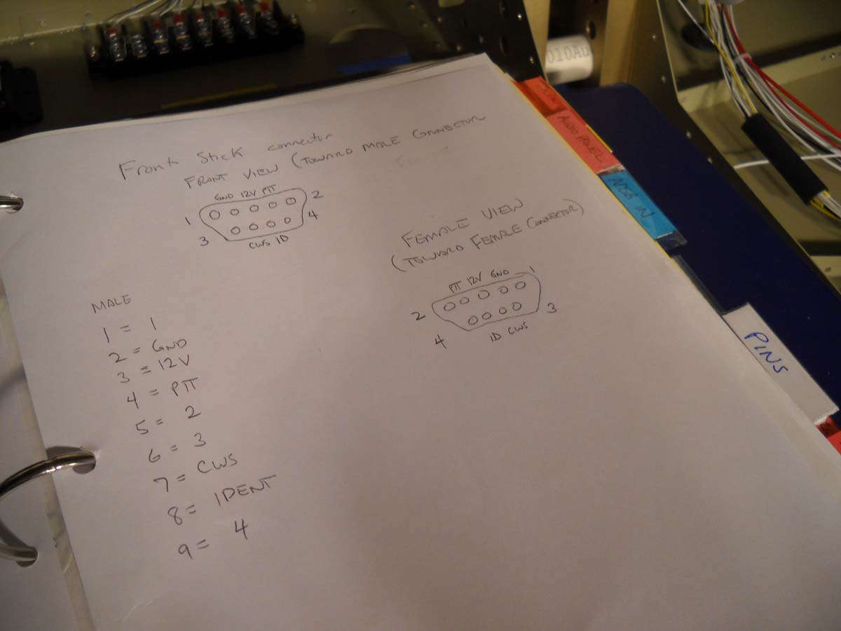
Keeping careful notes on the pin positions for the control stick connections. I hope to redo these, time permitting, but these notes will work for now.
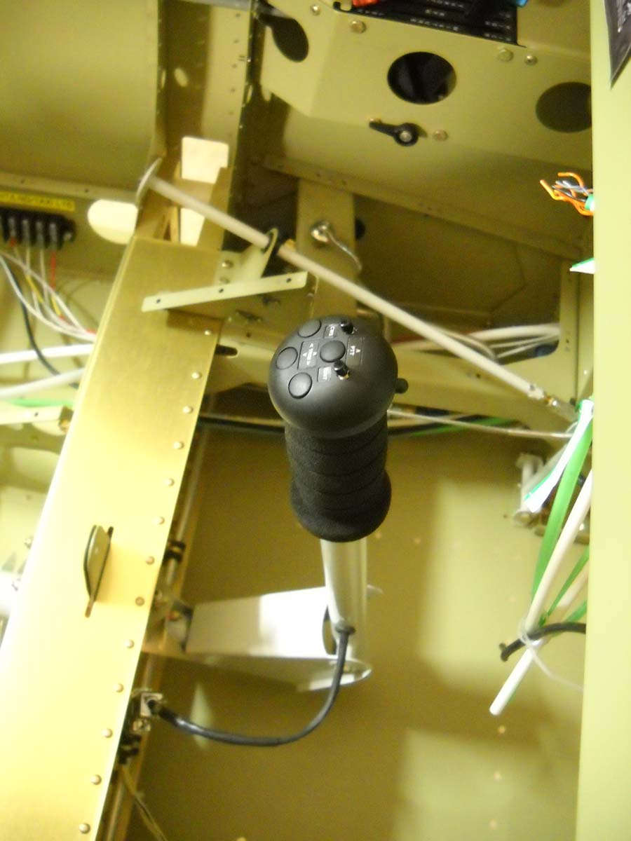
Here is the control stick connector finished and hooked up.
And a view of the front control stick essentially complete and ready for action...in a few years.
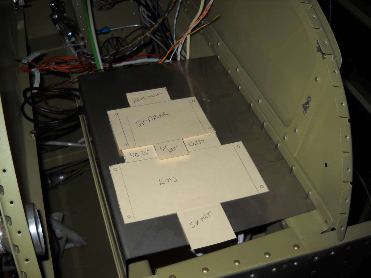
In the process of laying out where the "black boxes" are going to go. I am installing the Skyview system and made some paper cutouts of the Engine Monitoring System (EMS) box that has three wiring harnesses attached, and the ARINC-429 box, with two harnesses. The EMS obviously monitors the engine sensors and feeds that data to Skyview system via the network setup. The ARINC-429 box allows an interface with, for me, I hope, at Garmin GTN-650 WAAS/VHF receiver. There is not a whole bunch of room between the instrument panel and the aft bulkhead of the baggage compartment. What I think will work is a shelf installed on the two supports toward the right side of the fuselage, with the EMS installed right side up on the top and the ARINC-429 box installed inverted beneath it. I bent up a shelf that I think will work and test fit the size with the paper cut outs of the boxes fitting. I think there will also be room for the Skyview backup battery and the ACK E-04 ELT audio monitor also. Here is the tentative layout, but I have since cut the width of the shelf down to eight inches vs. the twelve I started with.
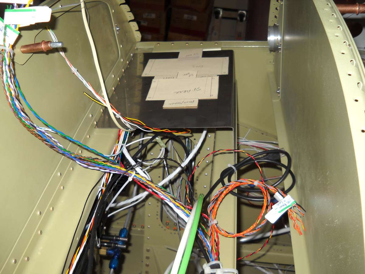
Another view from the other side. The ten inch Skyview main display needs about three inches of clearance behind it, so this will work okay for that. On the left side of the panel, the GTN-650 installation requires the full twelve inches available.
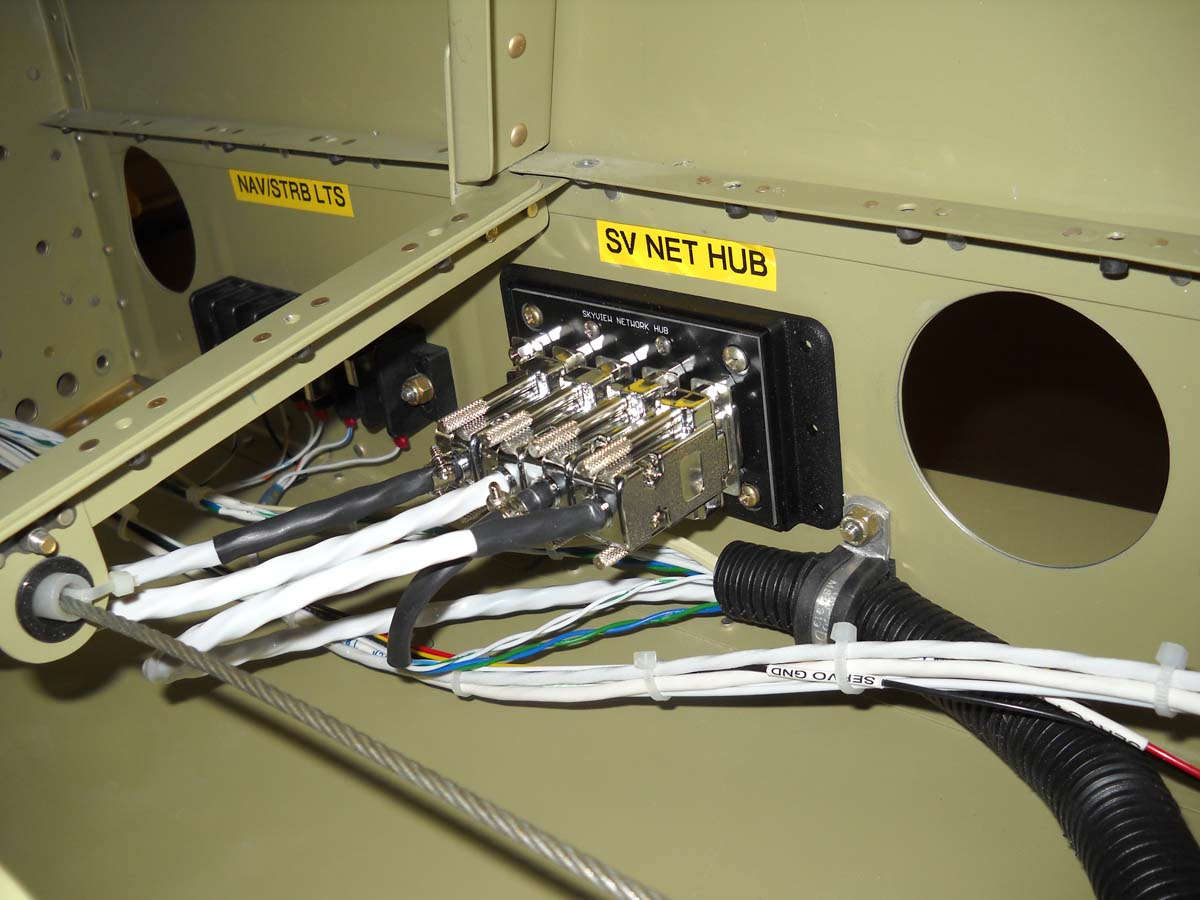
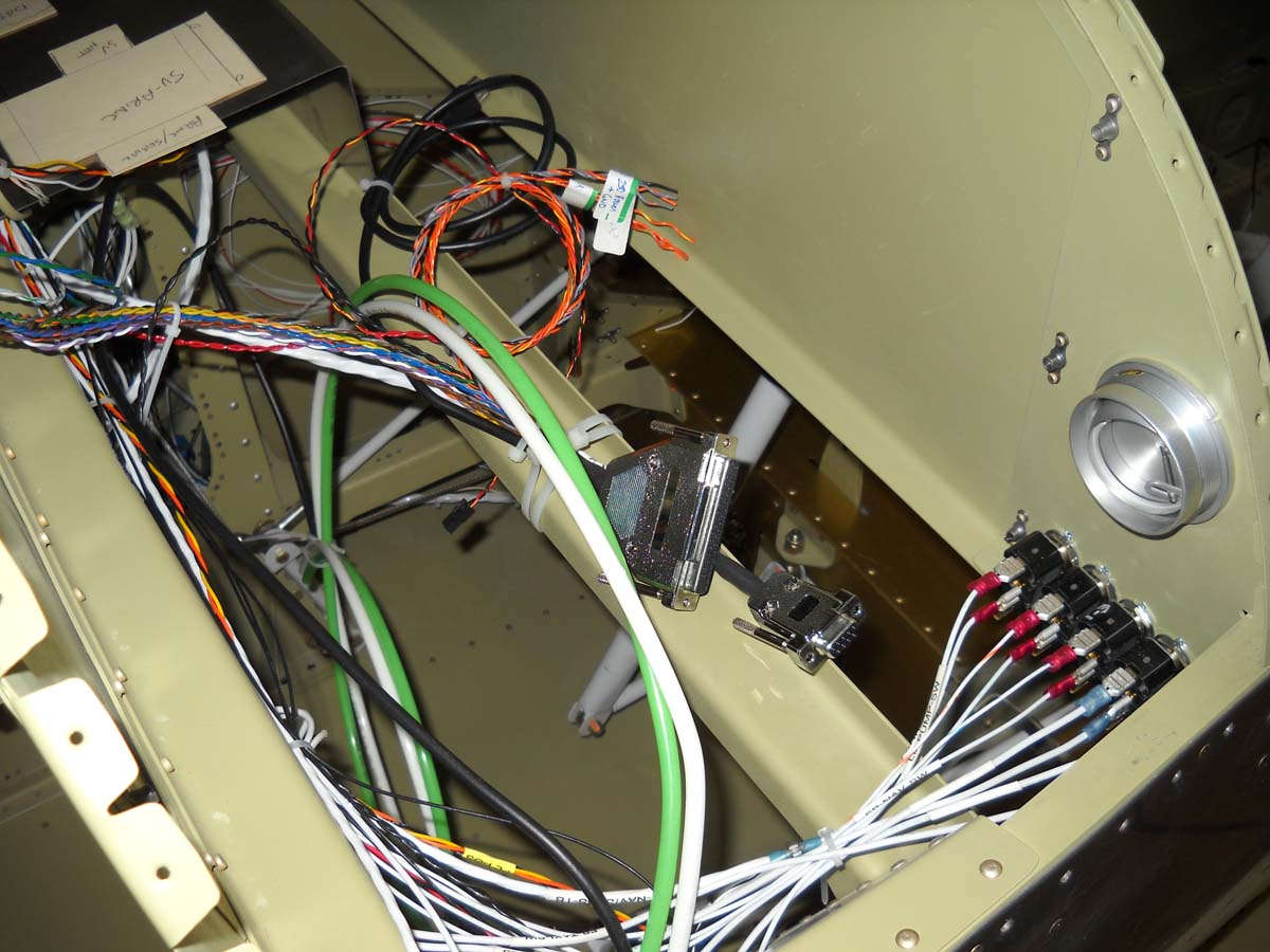
Here is where the SV-NET-Hub is installed on the right side of the fuselage beneath the pilot's seat area. Here four of the five ports are connected (ADAHRS, autopilot pitch servo, ARINC-429, and connection to the Skyview network itself. The last port will be used to attach the autopilot roll servo coming in from the right wing.
I pretty much finished the wiring in the aft end of the fuselage. Key to this was obtaining a ACK E-04 406 mhz ELT connector from the ACK folks....thanks to them but, then again, now I am committed, happily, to that ELT which I think is the best available in the price range.
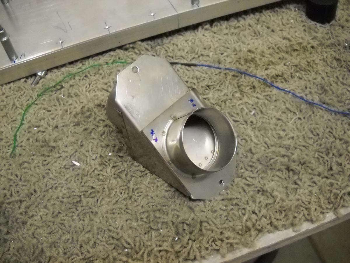
Having read numerous accounts of the less than stellar performance of the standard Van's air vents, I am replacing the plastic, poorly sealing vents with some very nice metal ones from Stein Air. Pricey but high quality. This necessitated me fabricating a replacement mount for the vent installed next to the aft stick for the rear passenger. This vent brings air in from a NACA vent in the right wing and is just ambient air...not heated.
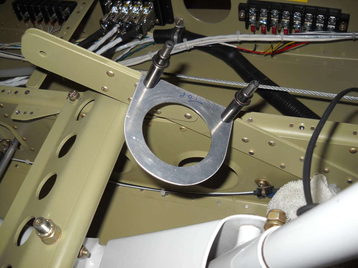
Here is the vent roughed into where it will be installed.
I purchased the Skyview main display harness and it is installed along with one of the network cables. The harness is prewired and awaits me to make each of the connections. I have spent quite a bit of time figuring out a "pin map", as it were, to get ahead of this process a bit in the planning.
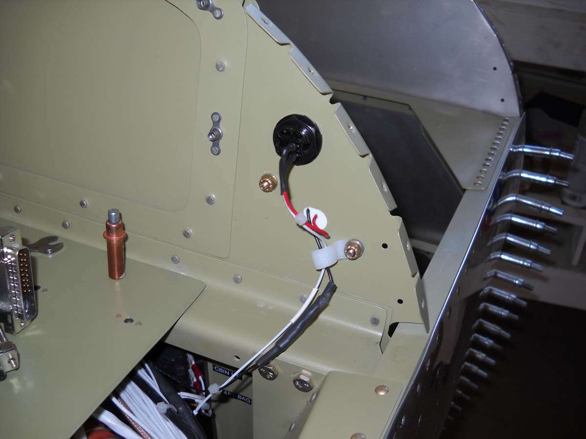
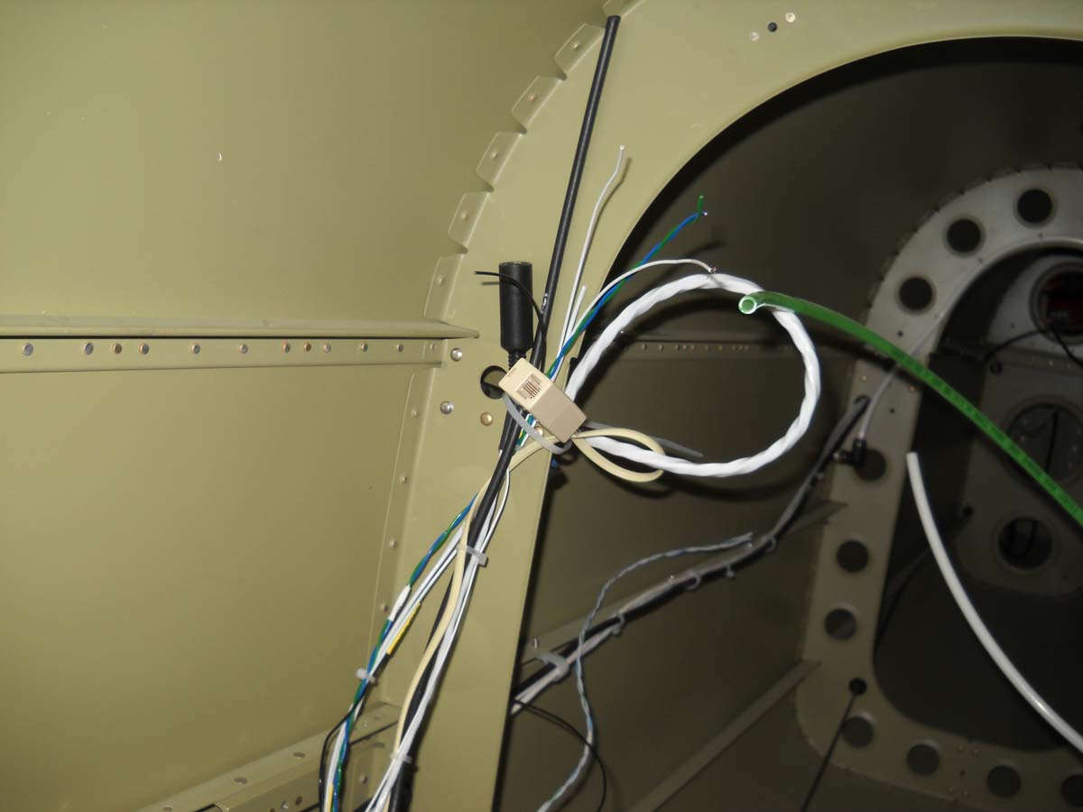
Back to the aft end, here is the ELT and Skyview XPNDR wiring ready to go and zip tied out of the way. The phone line connection is for the remote monitoring panel to be mounted on the instrument panel. The black connector is the one provided by ACK and required some tedious soldering of connections (thanks again, Duk!).
You can't see it too well here but the ELT and the Dynon XPNDR-262 units will mount vertically on a panel adjacent to the battery. When I had laid all this out I was not aware of the Dynon ADS-B box they had under development. That ADS-B box will allow direct reception of ADS-B traffic from those using the general aviation UAT transponders, and also the FAA weather feed from the ADS-B system. Combined with the Dynon XPNDR-262 ADS-B compliant transponder and the GTN-650 GPS position feed that goes into it, this should be a fully compliant ADS-B system that will interact with ATC and/or all other ADS-B and/or radar transponder equipped aircraft in the vicinity of this RV-8 when it is all hooked up and operating..
That is all to say that I don't have room for this added ADS-B box on the same panel as the ELT and transponder, and after talking to Dynon, they don't think it should be mounted adjacent to the ADAHRS unit that I plan on installing on a small shelf behind the bulkhead behind the battery. It might be okay but it also might cause some undesirable magnetic or electrical interference with the attitude and heading source for the Skyview system. This all makes more sense if you see it, but my plan is to add a second shelf to handle the ADS-B box. All the wiring is in for that shelf. I just need to fabricate and install the shelf which will be a bit of challenge due to limited access in the area.
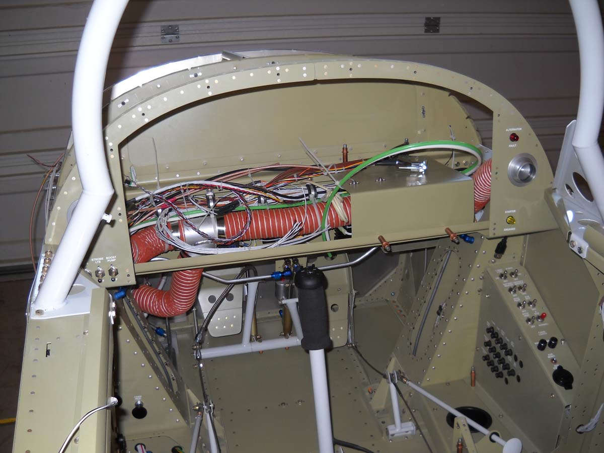
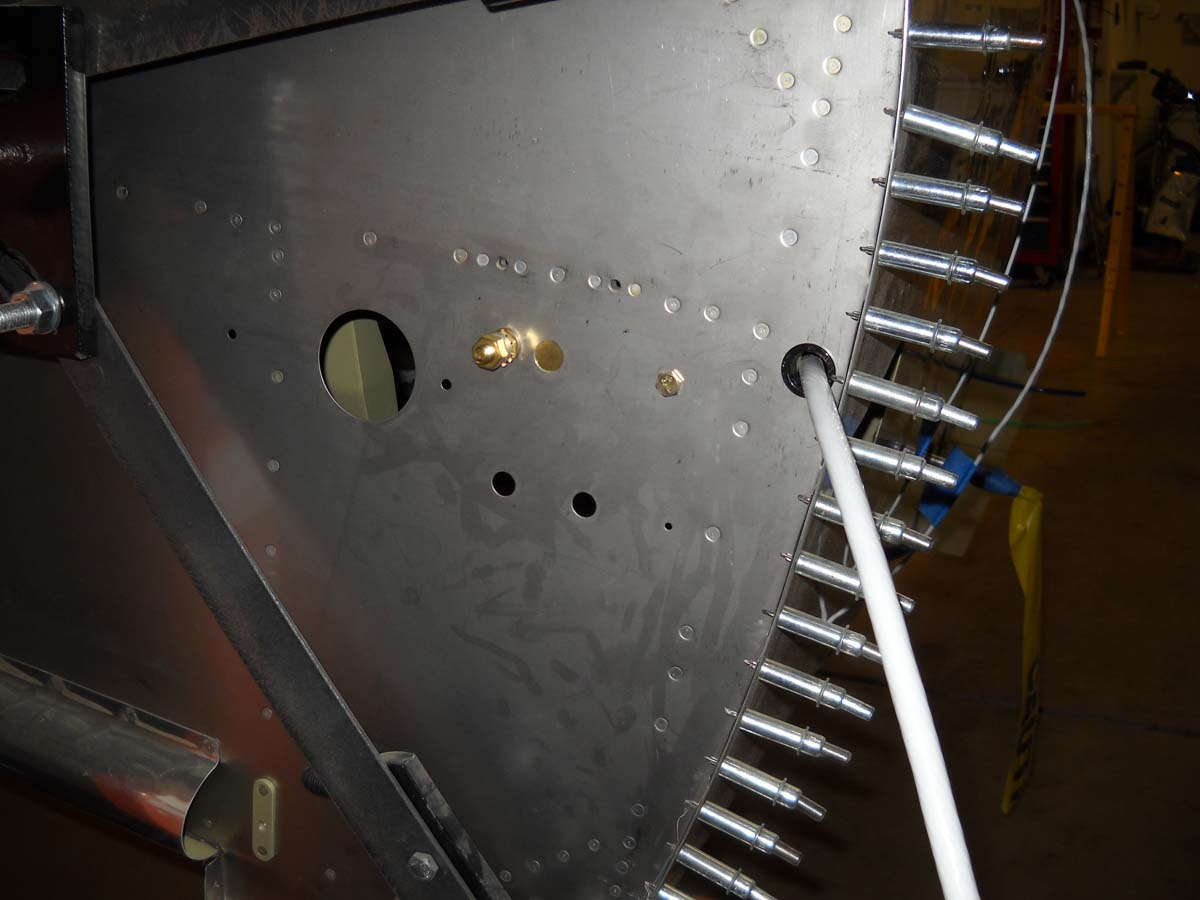
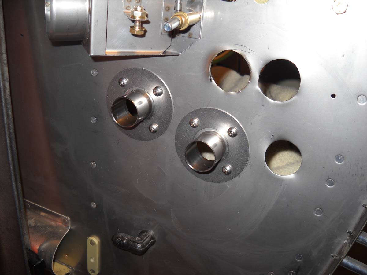
Turning my planning to the firewall and the pass throughs of wiring and air and fuel. My plan is to use a stainless steel heater valve that will connect through SCAT tubing to vents on the panel. I hope to have the three control cables (throttle, propeller, mixture) and two wire pass throughs. The idea, of course, is to seal the firewall against, well, fire. Like a wall. So, this is a before picture.
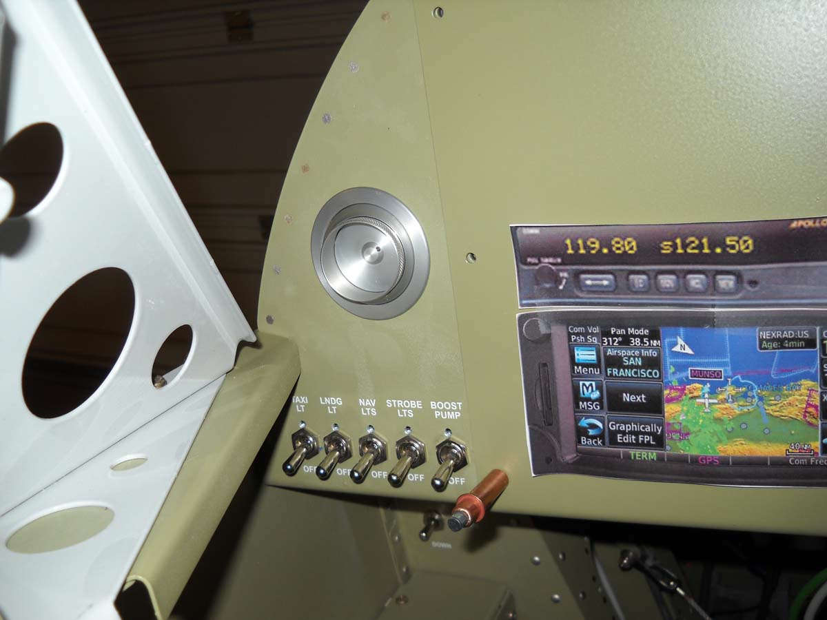
Here is one of the Stein air vents installed on the panel. The cutouts on the panel is for planning. The Garmin GTN-650 cannot be mounted this low on the panel due to the 11 inch plus depth; it would hit the structural cross member behind the panel so it needs to be mounted higher on the panel to clear that cross member.
Finally, here is a view of the aileron trim servo mounted below the floor with a AMP connector routing wires toward the front control stick and points forward.
Progress in little things is starting to add up.
February 20, 2013
Pressing forward on the wiring and planning for the black boxes that will be eventually installed. As a recap, my equipment plan as of right now is to install a Dynon Skyview system (single 10-inch screen) with a Garmin GTN-650 WAAS capable navigator, along with a second comm radio and an audio panel. Add to this the ELT and the Dynon ADS-B UAT receiver. Lots of $$ and lots of wires. But, on the plus side, I have been able to take the available information and pre-purchased Dynon harnesses and do much if not most of the wiring before I buy a single box.
Toward that end, I fabricated a second shelf to install in the aft fuselage behind the battery, this to mount that Dynon ADSB-470 Skyview interface module that will provide UAT traffic and weather inputs into the Skyview system to supplement traffic and ATC interface provided by the Dynon ADS-B transponder. I had originally thought to install this alongside the Dynon ADAHRS module but after contacting them, felt it would be better if it were mounted further from the ADAHRS unit to eliminate a possible source of magnetic interference. Thus, the shelf fabrication seen here being drilled.
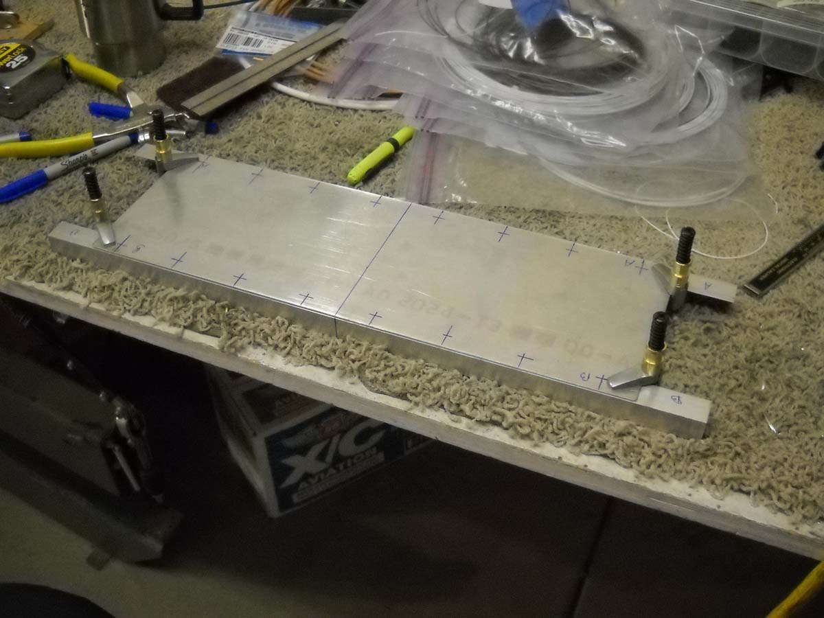
And here being finalized.
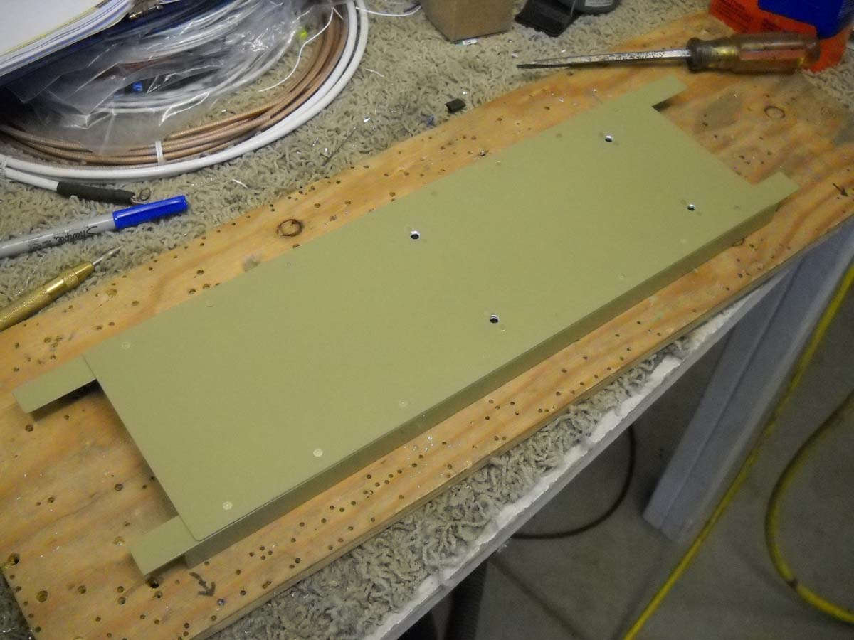
And here after being primed with the AKZO two part enamel primer that I have done the interior in, and then riveted together. The nutplates are also installed to accept the ADSB-470 module.
And here it is bolted into place. The adjacent wires are the two serial wires that connect to the Skyview system and also the power and ground wires. The shelf sits above the rudder cables and below the elevator pushrod. Fini.
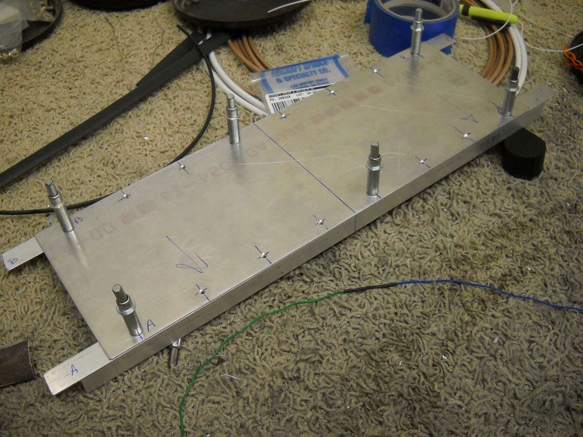
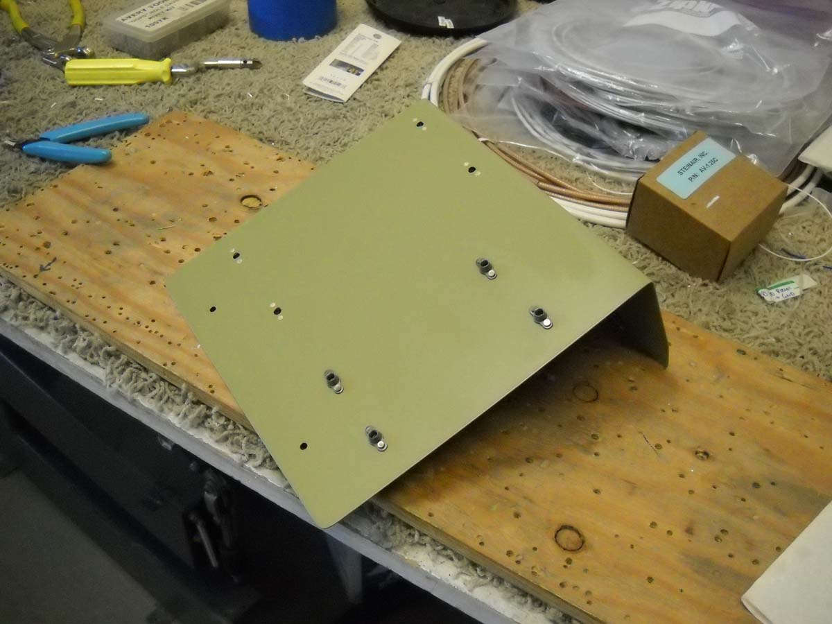
And here is the progress on the shelf I fabricated that will sit behind the instrument panel. It will hold the Skyview EMS module on the upper surface and the ARINC-429 interface module on the lower surface (mounted inverted). This will allow unfettered cable runs for the three EMS wiring harnesses and the two ARINC-429 harnesses. The EMS module is the nerve center of the Skyview engine monitoring system, and the ARINC-429 provides the interface to the Garmin GTN-650 navigator to allow navigation information to be displayed on the Skyview.
This view shows it completed with the priming and the installation of nut plates to accept the two modules.
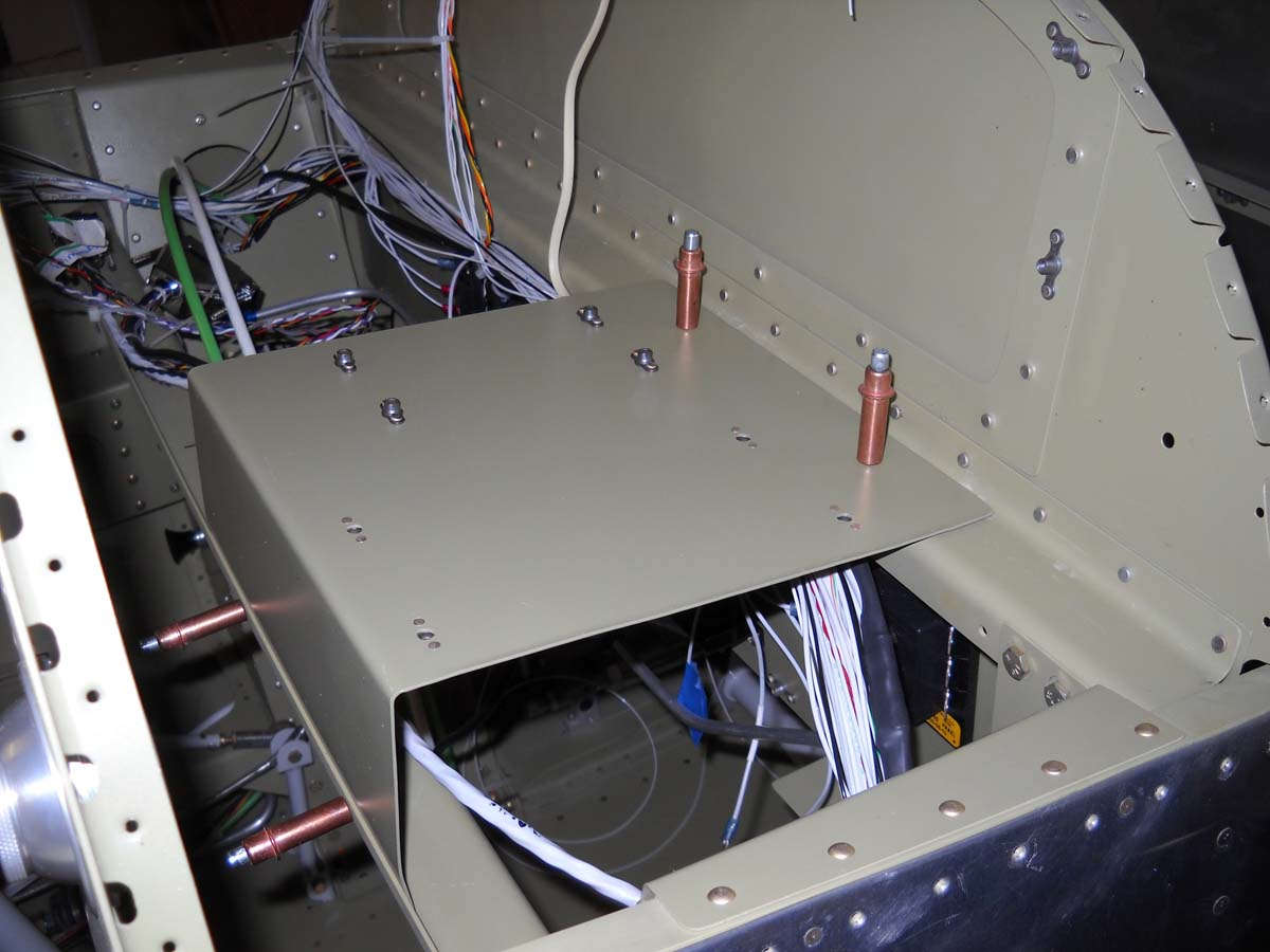
And here is where it will sit on the right side of the fuselage between the panel and the aft baggage bulkhead. Good place for it because it allows adequate clearance behind the panel for the Skyview 10-inch display and also the deep GTN-650 mounting tray that will go on the left side of the panel. If thing works out okay, this shelf will also hold the Skyview backup battery and ACK-406 ELT monitoring module. Fini.
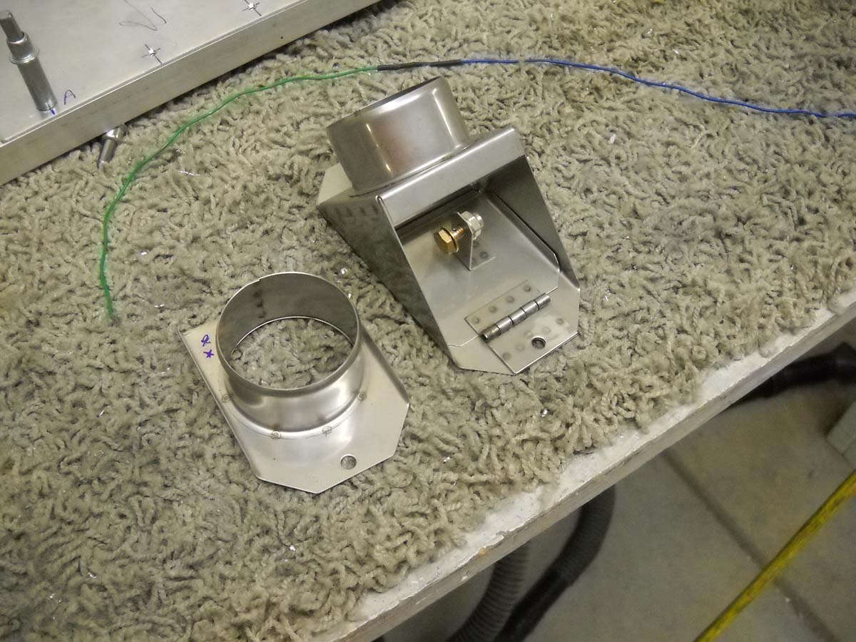
On to the bulkhead work. I am installing two instrument panel vents for fresh air/heated air to the cockpit, with one on each side of the panel. To bring the hot air in, I deviated from the Van's plans, which basically installs a heat manifold that dumps hot air heated by engine exhaust into the cockpit at the pilot's feet. I purchased this heater valve instead that mounts on the firewall. It is a two part piece, one forward and one aft. When I received the part from Aircraft Spruce and fitted it, I found there is major problem on the aft side in that there is a structural piece of angle that does not allow the part to fit. The solution was to cut the part down to size and then rivet it into position on the end near the structural angle. Thus, I cut it in half which seems to work out okay. Not sure how others have done this because I was following along behind others that have done the same thing. I know some guys have moved this valve and the hole required around on the firewall but I see no need to do this.
Another view of the two parts, the one on the left to be mounted on the aft side of the firewall, the one on the right on the forward side.
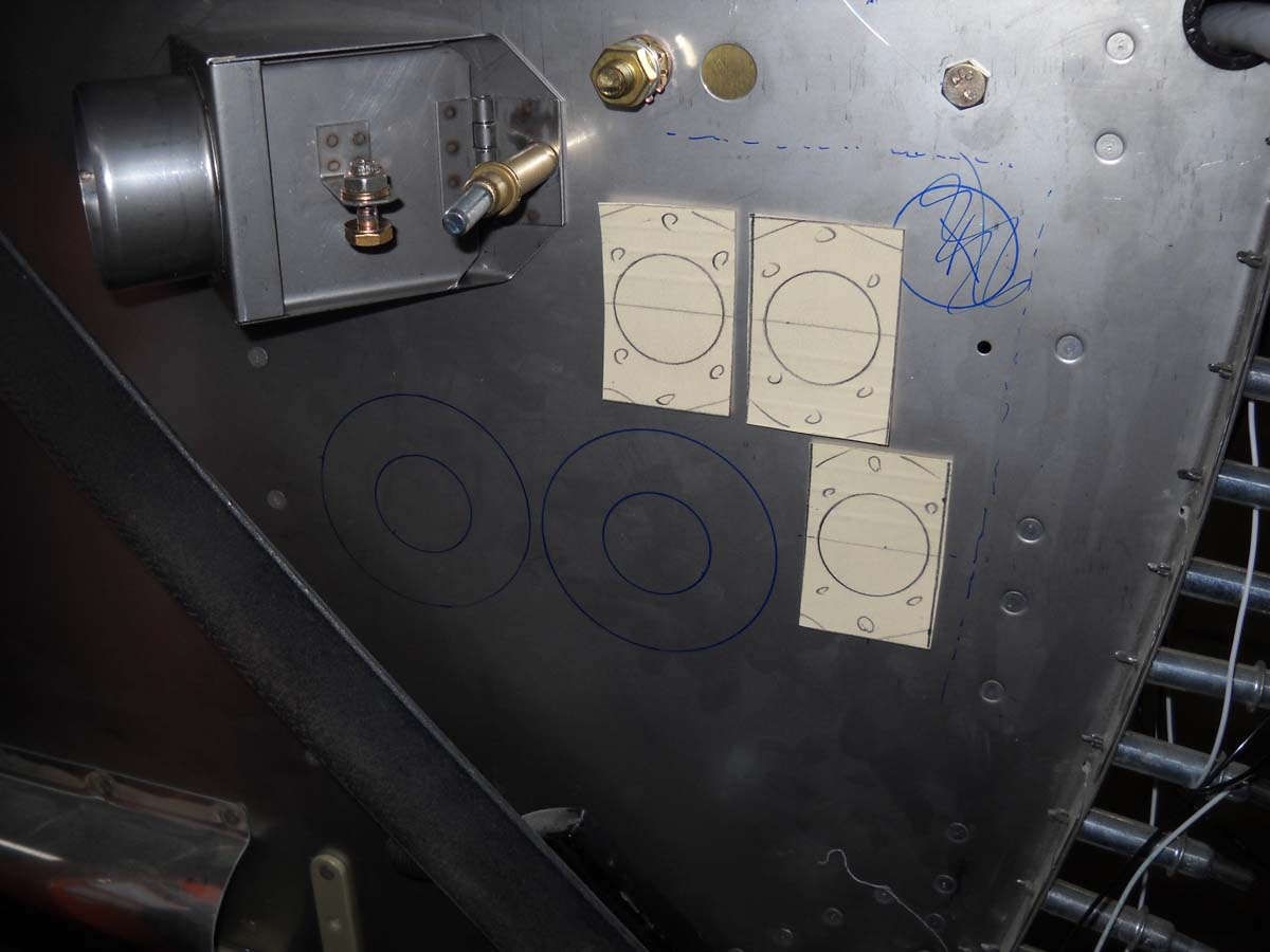
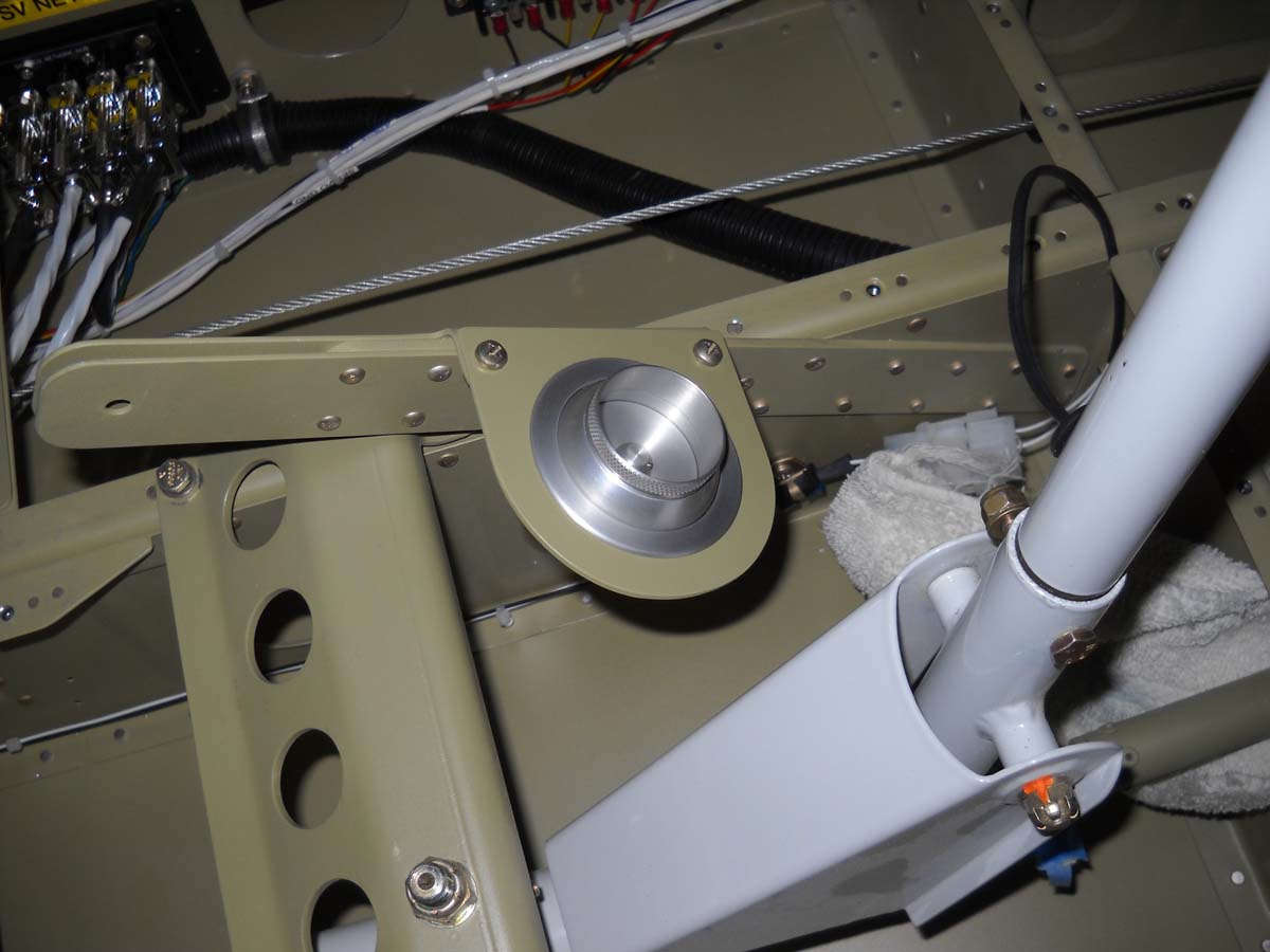
Here is the valve in position on the firewall. I had to buy some stainless steel hardware to mount it here, and plan to use a single cable to 1) modulate a valve on the cold air NACA vent and 2) modulate the valve on this heater box. My plan is to pull my control handle and close the incoming cold air and open the incoming hot air to allow temperature control. Again, this is not my idea but another copied one. The internet is a wonderful thing, as are RV-8 builders who have gone before me.
This view also shows my initial planning for the firewall pass throughs. The paper cutouts are three pass throughs for the throttle, propeller, and mixture cables positioned to accommodate the space required. The two doughnut looking markings to their left and below the valve could be the two electric wiring pass throughs. I am using the SafeAir 1 components. Again, some guys move these around on the firewall and I can't really see why unless you have a forward mounted battery, which I don't. I am planning on leaving the forward baggage compartment intact and this is really the only place these pass throughs will work if you do this.
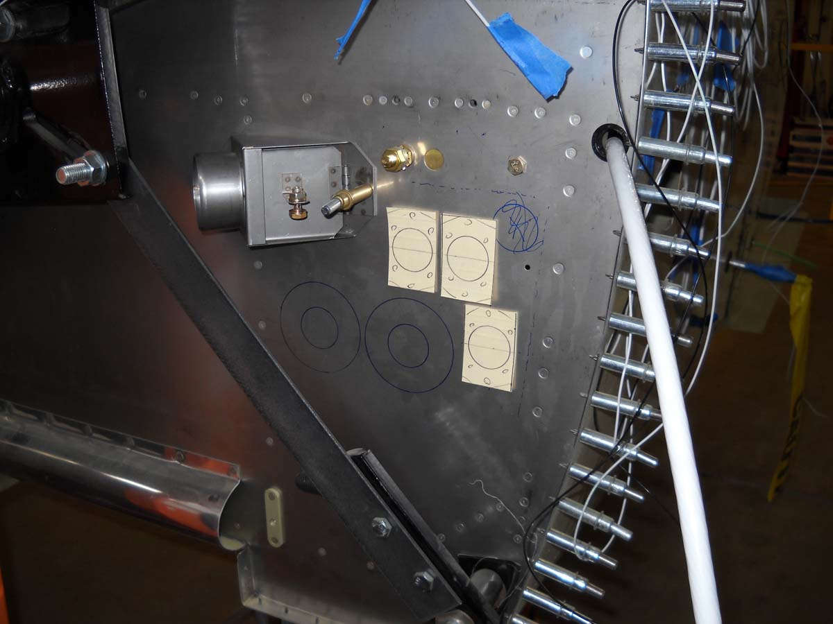
Another view. The big white cable on the right is from the battery and will move to one of the new pass throughs, and the hole the cable comes through right now will probably be used for the cable that will control the heater valve. More to follow here as I try this out for size.
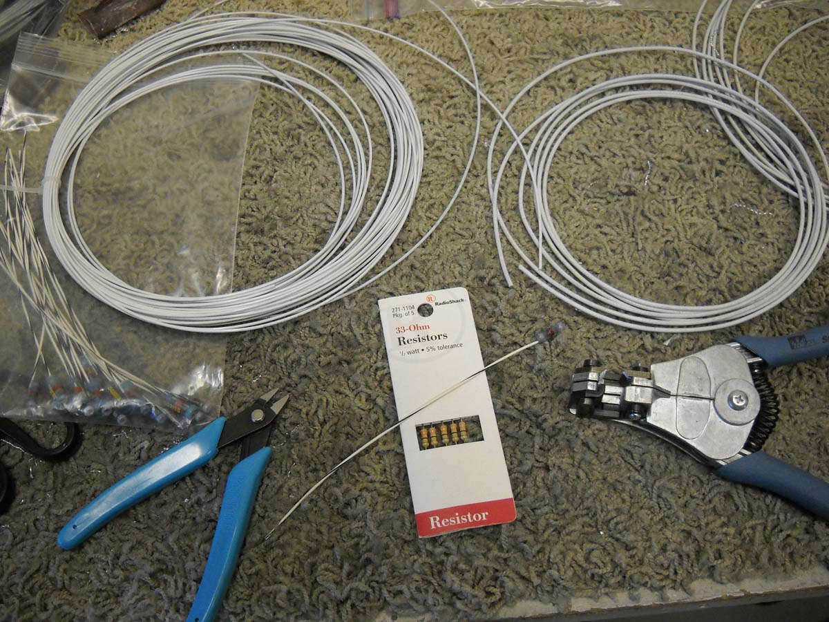
On to fabricating P-Leads for the magnetos, and the accompanying engine RPM pick-offs for the EMS system. Basically what we have is 20 AWG single conductor shielded wire that will be used for the P-Leads. For those not familiar with P-Lead on conventional magnetos (and I was not until recently), these are the wires that ground the magneto to make them little but hunks of metal and not capable of firing spark plugs with the slightest movement. You want the magnetos out of service when the switches are off, so the magneto is grounded through the magneto switch in the cockpit back to the wire shield which is grounded to the magneto. Thus, when the magneto switch is off the grounding circuit is completed.
To add to this, as per the Dynon EMS instructions, I am using 20 AWG unshield wire to connect the P-Lead electric impulses available when the magnetos are live to provide an engine RPM input into the EMS. To reduce the impulses to a acceptable level resistors are added to the circuit between the P-Lead pick off and the EMS. I can barely spell resistor but I can read directions.
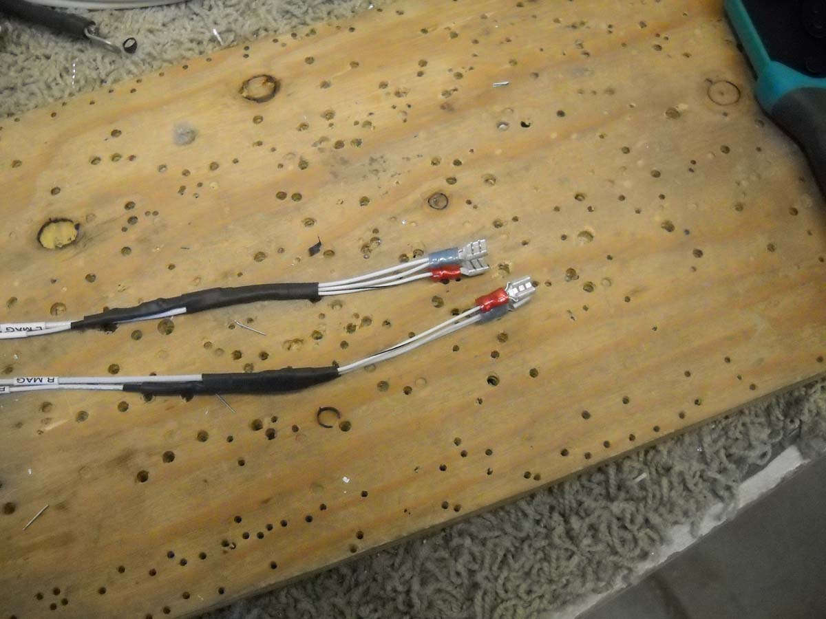
For the P-Leads, I stripped the outer insulation off to reveal the wire braid shield. I then cut this back to maybe a 1/4 inch available braid. This allowed me to install a solder shield with an attached wire over the exposed braid to provide a sold connection from the shielding to the attached wire.
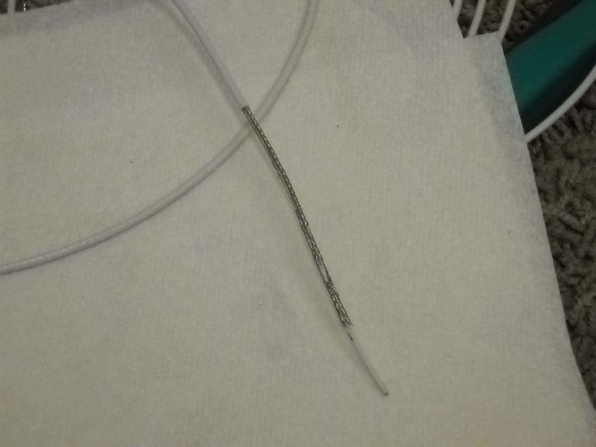
So here is the result. One of the wires coming out of the heat shrink is the grounding wire to the shield (braid) and the other is the 20 AWG conductor wire. These ends will be attached to the magneto switches in the cockpit; the other end will be attached to the magneto. Two magnetos, two P-Leads.
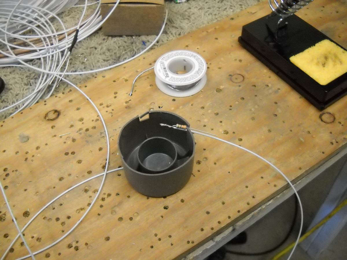
Now, for the engine RPM pick off for the EMS, I prepare to solder the resistors inline on each of two wires. A master soldering person I am not, but with the help of Radio Shack and the EAA Hombuilder Hints online videos, here we go. The proper sized resistor is being soldered to one of the wire leads.
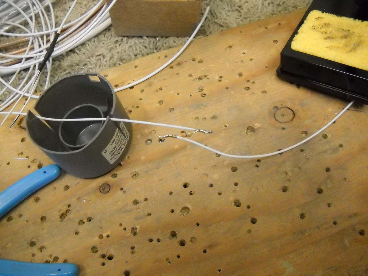
And here the resistor is soldered in line on the wire. The EAA Hombuilder Hint was to solder them in this arrangement to add strength to the connection in that the resistor has no stress placed upon it. When heat shrink is added, the wires are carrying the entire load and the resistor is along for the ride just resisting, I guess, electrons. It's all smoke and mirrors as far as I can tell; I just follow directions.
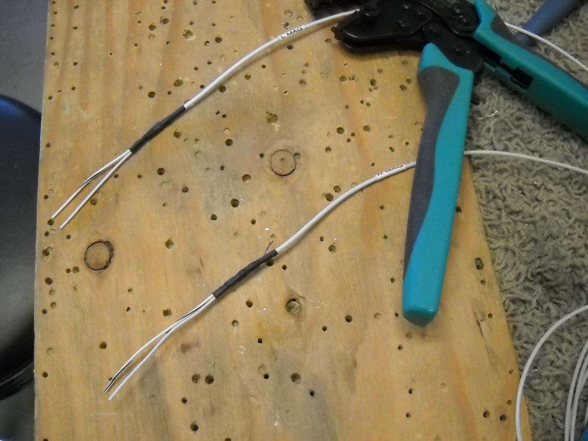
End product is the P-Leads and the RPM pick-offs all ship shape with heat shrink. The P-Lead and RPM pick-offs share one terminal (blue) and the P-Lead ground gets its own (red). These will be connected, again, to the cockpit magneto switches soon enough.
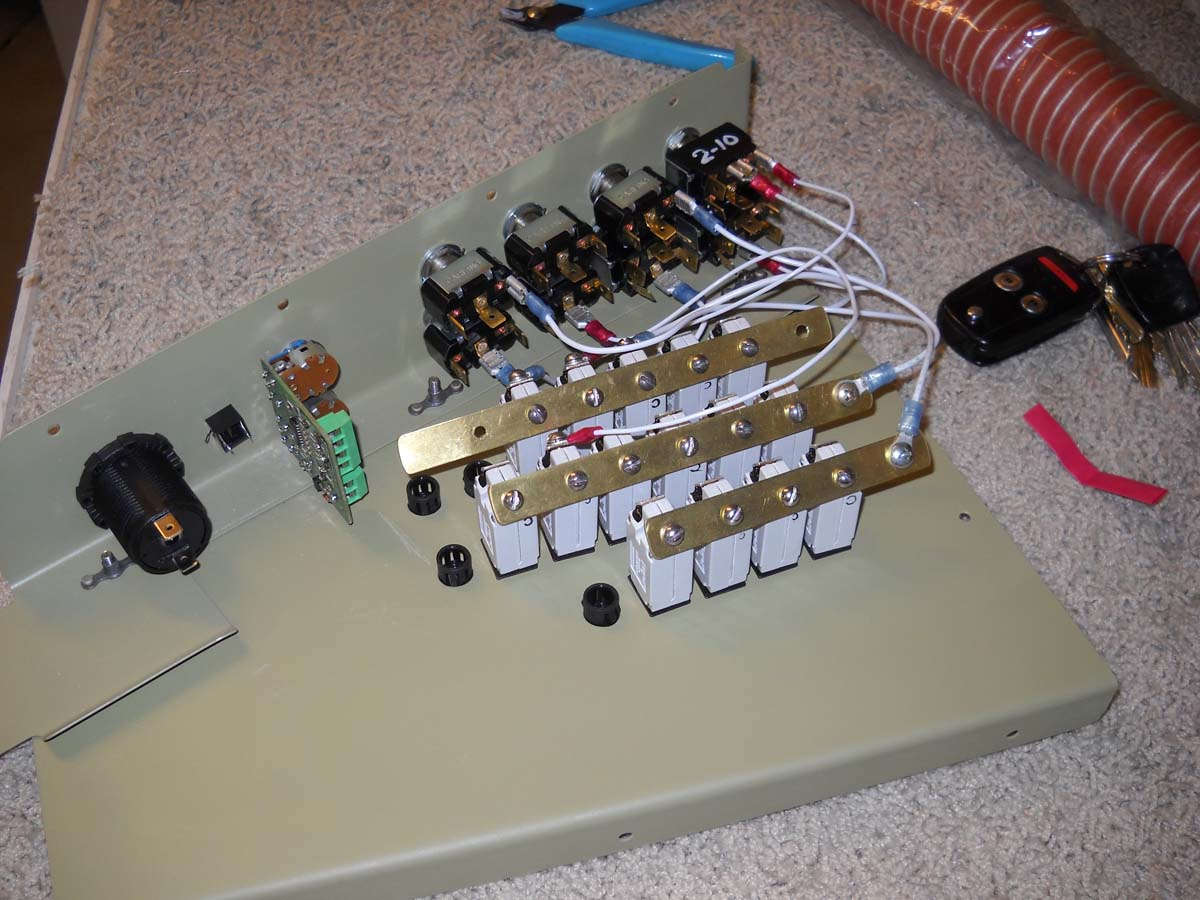
Here is the building wiring bundle that is about ready to be connected to the cockpit switch panel/circuit breaker panel. I need to do a bit more work on that panel to move some things around and also add some lighting controls to it, but it will be installed here in the near future. Wiring aft of the instrument panel is just about done, save one or two wires like the OAT sensor that I don't have and won't have until I buy some black boxes from Dynon.
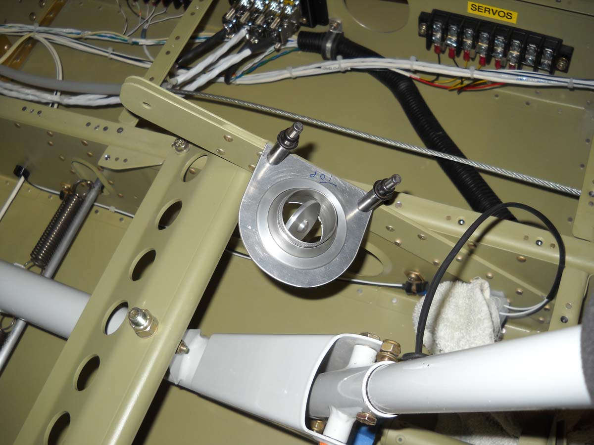
And, as a follow up, I also finished the vent mount for the aft cockpit and it now installed and ready to accept the SCAT tubing. This vent provides only ambient air (from the NACA vent in the wing) so I used a Steinair vent that completely closes here so that air flow source can be turned off if desired.
So, a couple of weeks of work and I continue to make slow but steady progress.
March 4, 2013
More work on the electrical system, with an emphasis on fleshing out the last major parts of the wiring and working on the firewall pass throughs for both the wiring and engine control cables.
I had earlier decided to pretty much stick with the Van's plans for running the engine controls and the wiring through the firewall, that is, on the lower left side of the firewall while looking forward. I had to increase the diameter of the two engine control cable holes to 1 1/8 inch and add a third engine control cable hole (throttle, mixture, propeller controls) and add two more 1 1/8 inch diameter holes for the wire pass throughs.
I did not have a 1 1/8 inch punch so I decided a step drill should do the job. Not. At least for me, the Harbor Freight step drill does not do a good job at stainless steel at any RPM or with any lubricant assistance I tried. The two holes I completed were ugly but ultimately usable.
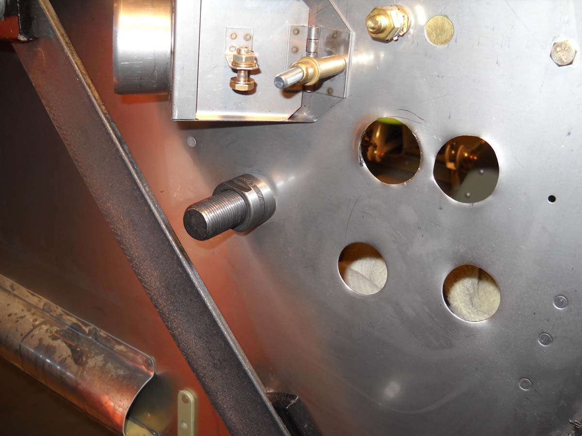
I finally located a 1 1/8 inch punch that I was able to borrow. Much, much better in the final result. Stainless steel is hard to work with in any case, but putting big holes in it is a real pain. This photo shows four holes: the top two are step drilled, the bottom two are punched, and the fifth hole is being punched on the left under the heater valve.
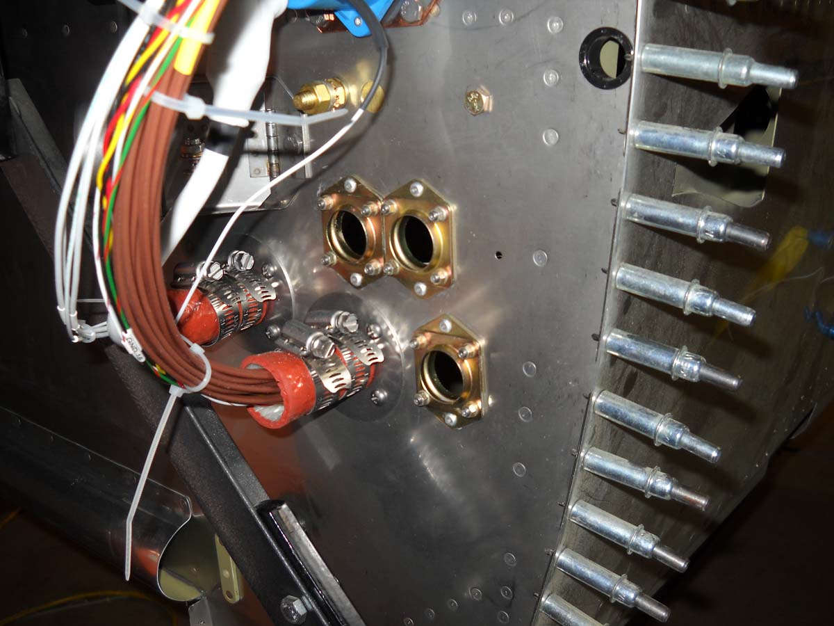
Holes are done and finished. The two SafeAir 1 wiring pass throughs are drilled and mounted in position.
And, the two wiring pass throughs ready for wires. The control cable pass throughs are ready to accept the Doubletree Model 7001 steel eyeballs that are on order.
A view of the left forward fuselage looking down toward the fuel pump with some of the wiring going forward through the firewall. Wire labeling is waiting to get heat shrunk onto the wires.
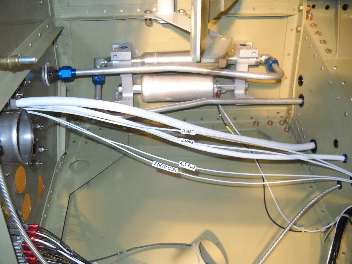
A forward view of the wiring pass throughs with the battery and other wires penetrating.
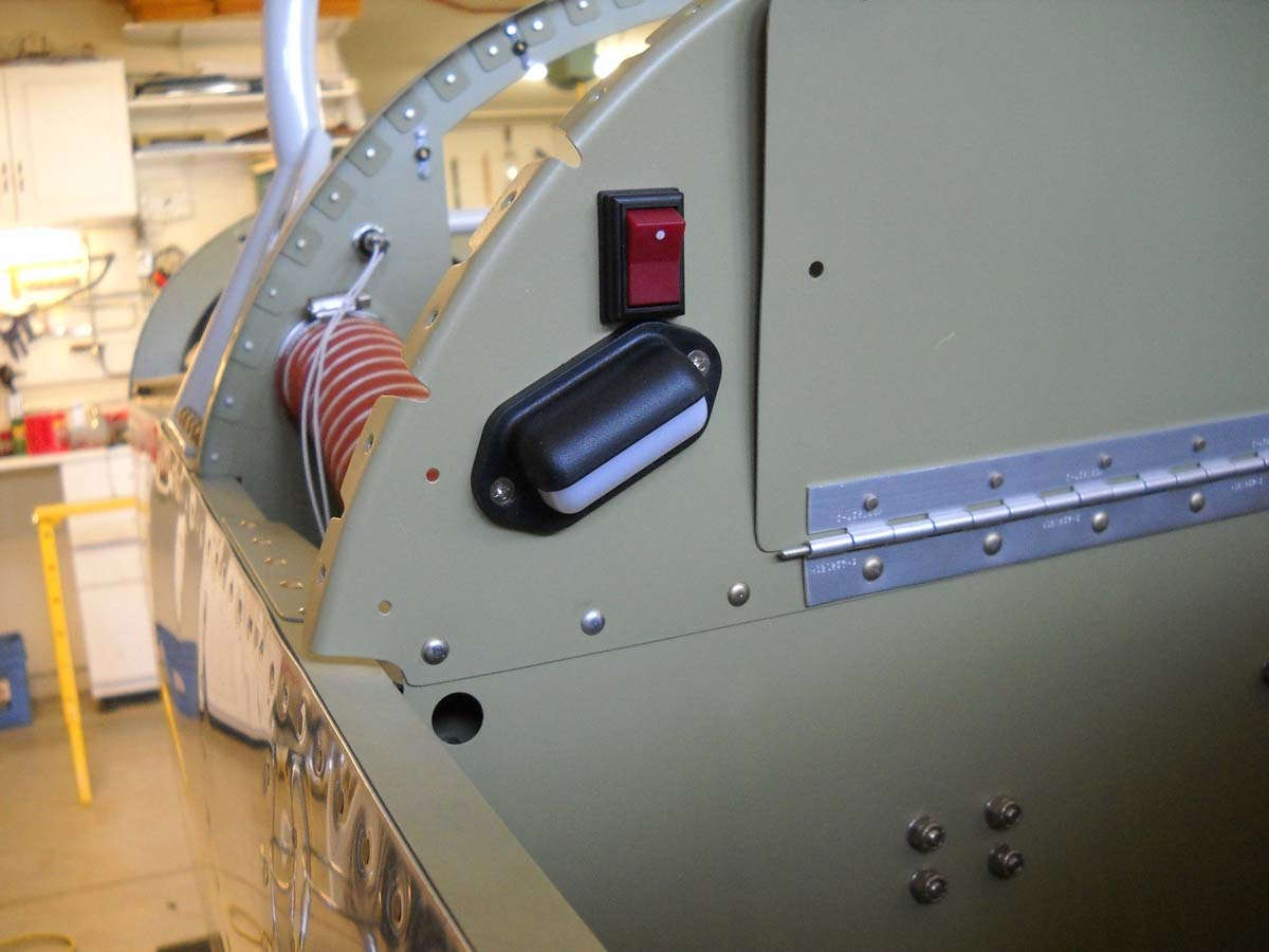
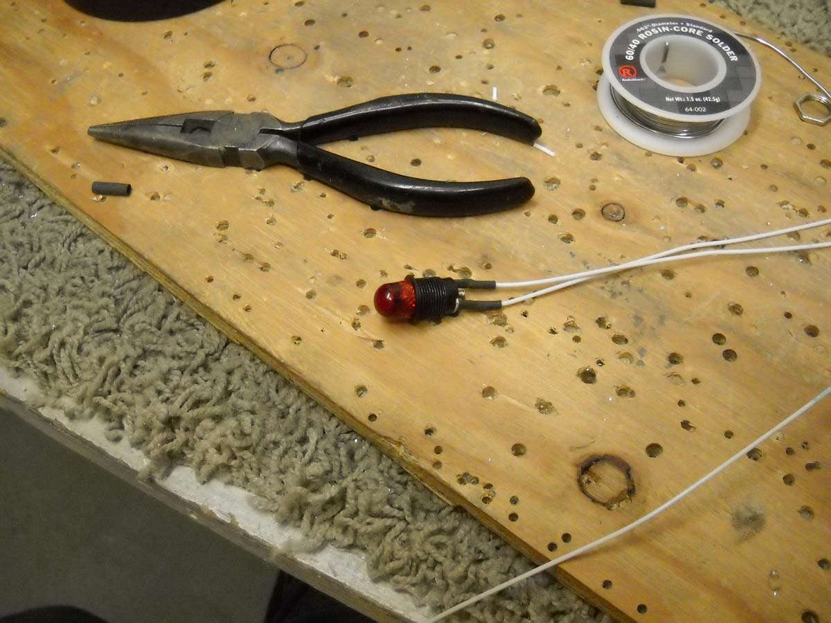
I will have three warning/informational annunciators on the instrument panel: an alternator fault light, an EMS fault light, and a starter engaged light. The first two are red, the last one yellow. Here I am soldering on leads to one of the lights prior to installation on the panel.
And here it is ready to be mounted and wires run.
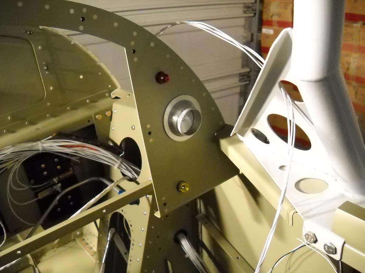
You can pick out the alternator fault red light and started engaged yellow light here on the right side of the panel. A placard marking will be added to each. The started light will be in plain view next to the starter switch. These lights are not absolutely needed but both are easy to install and both the starter contactor and alternator already have provisions for them.
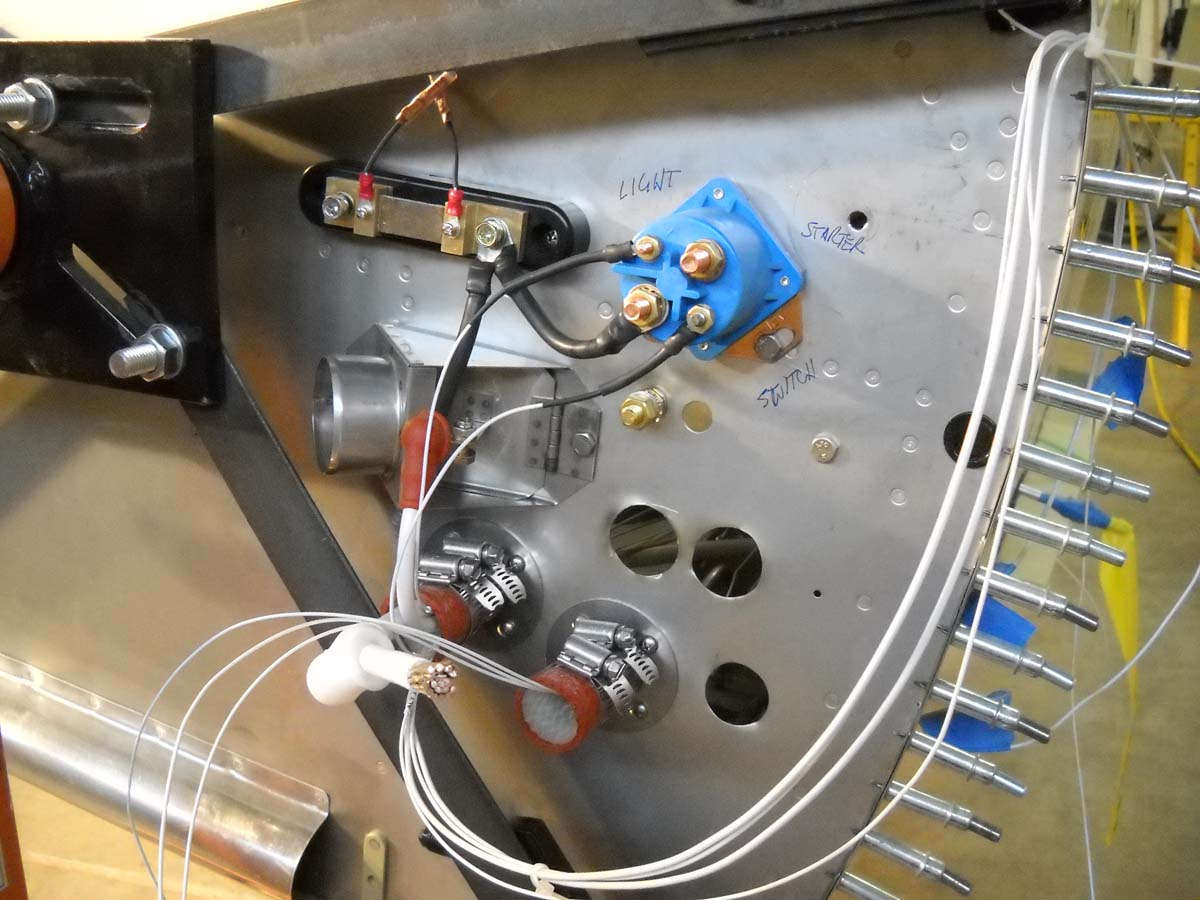
A final view of the firewall for the week with the B&C brand starter contactor (blue case) mounted on the firewall, with the Dynon shunt mounted adjacent to it. The shunt will provide an electrical system sensor input to the Dynon EMS. I used 6 AWG wire between the two, with heat shrink added for protection. The wires that someday will go from the shunt to the current limiter to the alternator will also be 6 AWG.
On the shunt, the two pigtail wires going up from the shunt are fusible links I made out of 26 AWG wire to protect the EMS. These will be mounted downwards and connect to the EMS via 22 AWG wires that can be seen emerging from the pass through on the right. Still need to crimp on the connector for the 2 AWG battery wire before it is connected to the contactor. The two small terminals on the contactor have the starter switch wire and starter engaged light wire attached. The empty terminal will go to the starter motor when it is later installed.
Coming in short order: all the firewall forward EMS wiring will be installed so I can complete the wiring behind the panel. Also, the headset shielded wires will be installed with jacks at one end and the other end positioned for the eventual location of the audio panel. Finally, the switch and circuit breaker panel, already constructed, needs to be modified a bit and then it will be installed. After all that, I will do some wiring checks to make sure all is hooked up properly, or at least what I think is properly right now.
March 19, 2013
More work on the electrical system, finalizing the configuration of the wiring and the systems that it ties together.
The Dynon EMS harness was wired in, including the myriad of ties to the engine sensors monitored by the EMS. I completed the pass throughs of the EMS wiring and is seen here with the other wiring forward of the firewall.

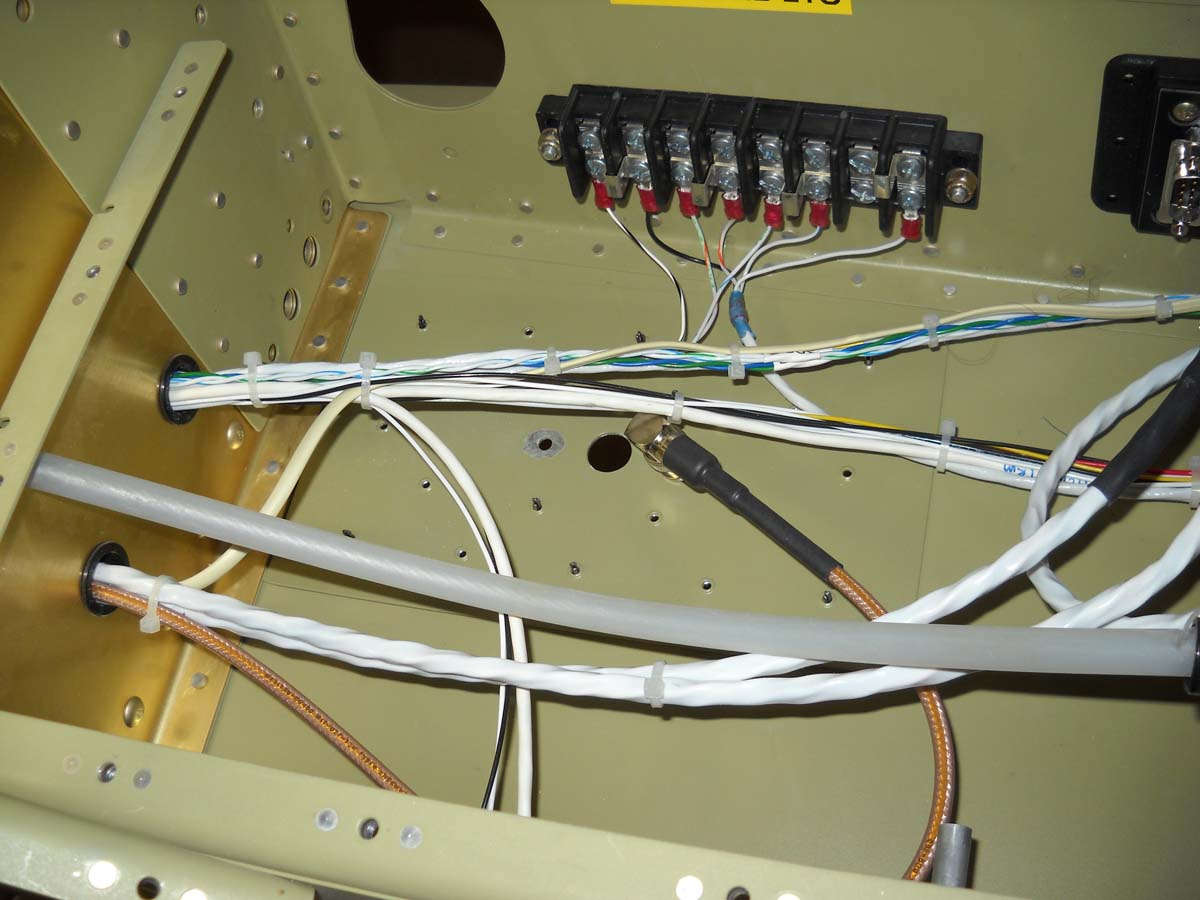
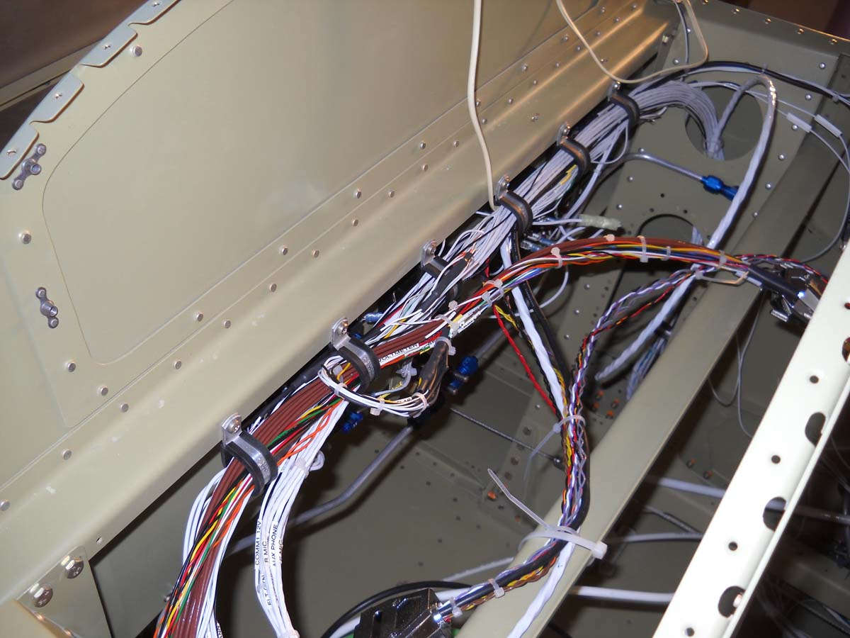
Here is the current state of the wiring behind what will be the instrument panel. Wiring comes up and goes down on each side through the landing gear towers and is linked to fuse panels and connectors. The wiring in this area is just about completed now.
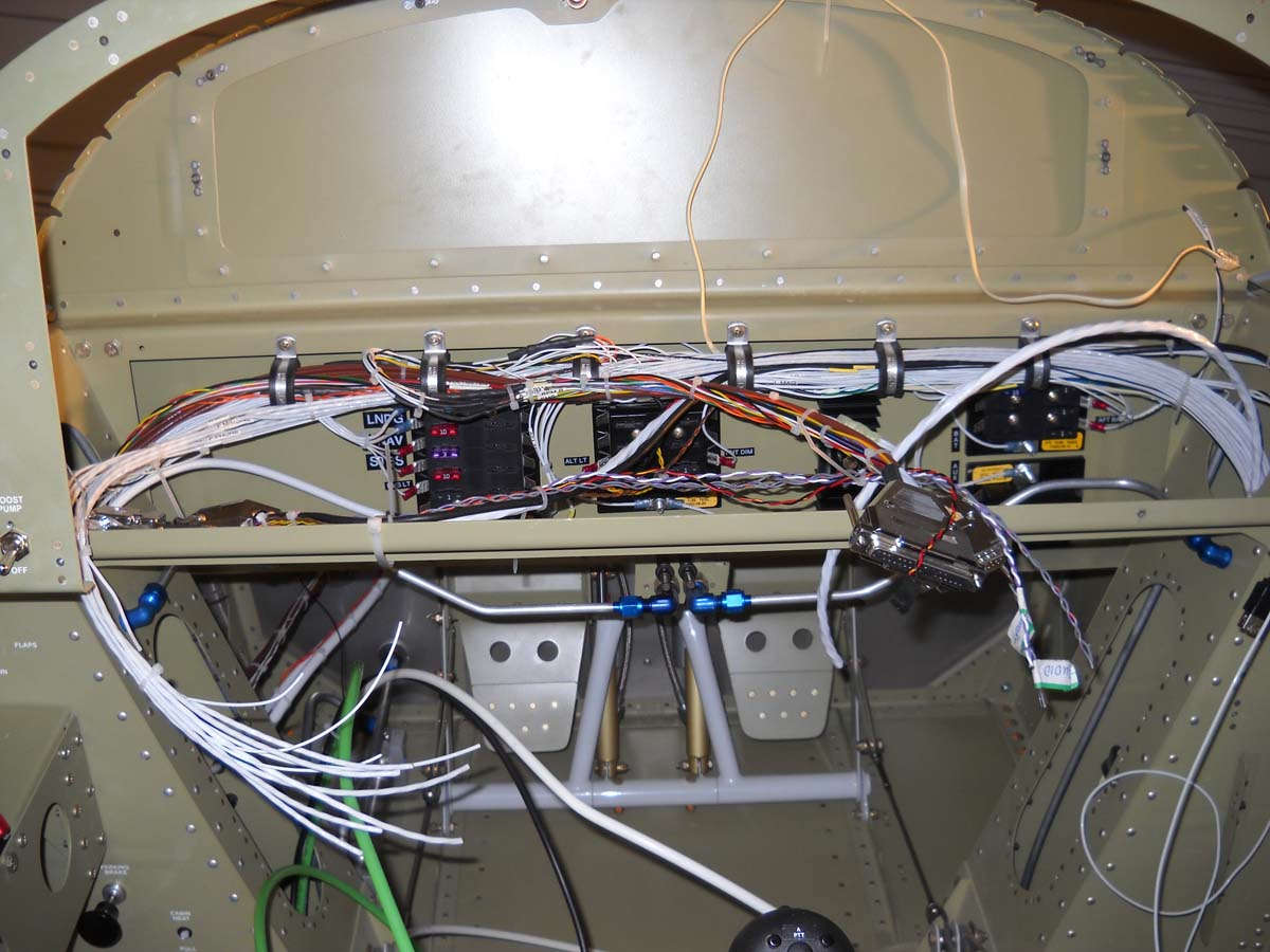
Another view. There are three Dynon connectors here plus several Dynon network connectors plus wires pulled for the GTN-650, the second comm radio, and the audio panel.
The two Dynon EMS connectors are on the left, with the main Skyview display connector on the right. The wires looping around the display connector will eventually be wired into the other panel avionics (audio panel, GTN-650, and second comm radio).
Part of the process of finishing the wiring, here I am wiring in an 12 volt aux power connector into the aft cockpit (turned sideways). The hole is being punched into the arm rest to accept the connector. To the right of the hole on the other panel is the mounted map light dimmer switch and the two headset jacks, one for audio and the other the mic.
Here is the installed 12 volt aux power connector completed.
Here is a view of the two headset jacks for the front cockpit (still sideways) installed on the aft side of the center section bulkhead near the top of the fuselage side. Should work just fine there. It took a fair amount of research to get the wiring correct on these jacks. Three wire shielded cable was used to run to the audio panel, and the mic jack had the push-to-talk grounding wire from the control stick wired in also.
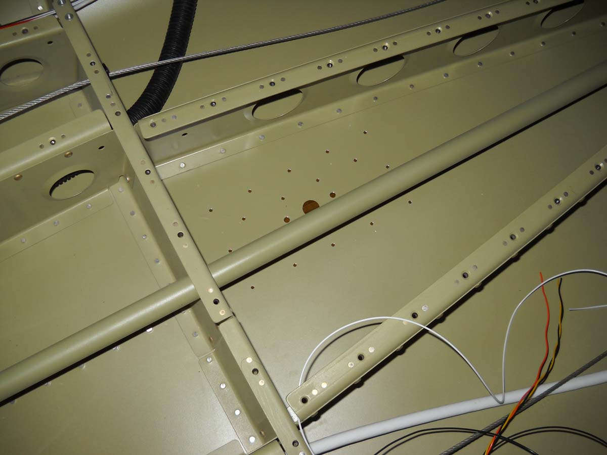
I scratched my head a bit trying to figure out how to secure the wiring bundle coming up from each gear tower to the area behind the panel. This was my solution: a piece of angle aluminum cut to size and used to mount an appropriate Adel clamp to secure the bundle. I was just fitting the angle, intending to prime it and then install but it was such a pain to get it into position I might just leave it installed and unprimed right like it is.
The pair of wires going off to the upper right are for the forward baggage compartment light. Like I said, I thought long and hard and think just about all the wiring is in place now, including switches.
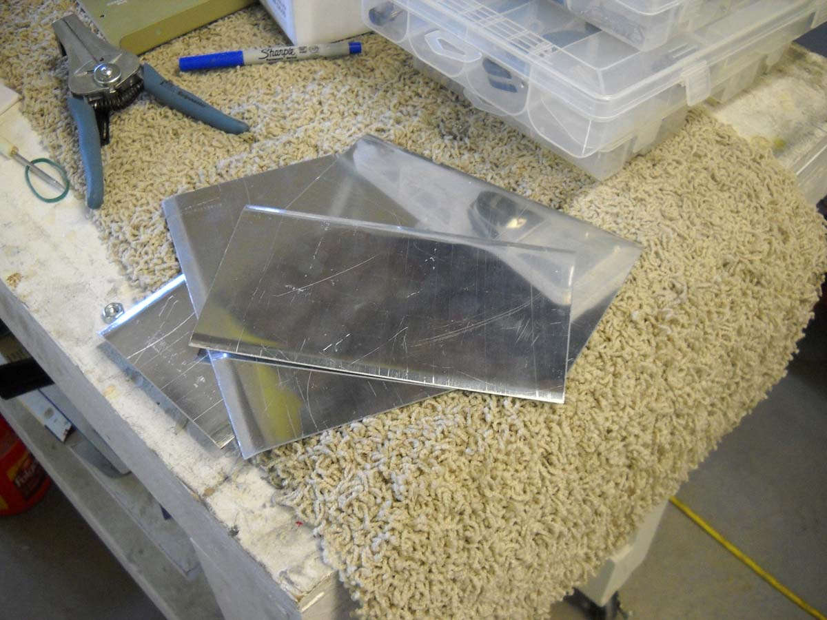
Finally, here are the four pieces of aluminum stock cut for use as antenna doublers. They need to be finished, fitted, and drilled for the antenna and rivets that will hold them to the interior fuselage bottom skin.
I hope to do that prep work next Saturday and finalize the doublers also, at least to the point where they can be primed and set aside for installation.
Also, I plan on making some changes to the circuit breaker panel that will require a bit of work. Once that is done, it will be reassembled and fitted with the switch panel into position and the wires attached to the switches and circuit breakers. At some point after that, I plan to do an extensive continuity check of wiring, breakers, and switches.
April 2, 2013
Moving forward, I've worked on a bunch of little projects to complete the electrical system and associated stuff.
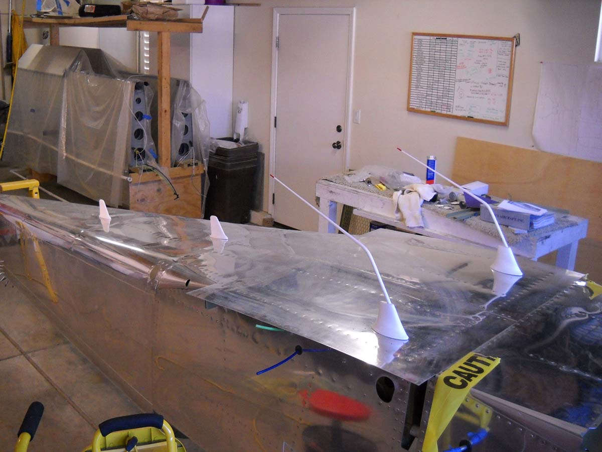
Among those was fabricating the antenna doublers and prepping the antennas for installation. Here are four antennas, two VHF comm antennas and one transponder antenna and one ADS-B antenna. These antennas were all purchased from Delta Pop Aviation based on various recommendations, and are designed for experimental aircraft. The holes are now drilled and the antennas fitted, then put away for future installation once the fuselage is on the landing gear.
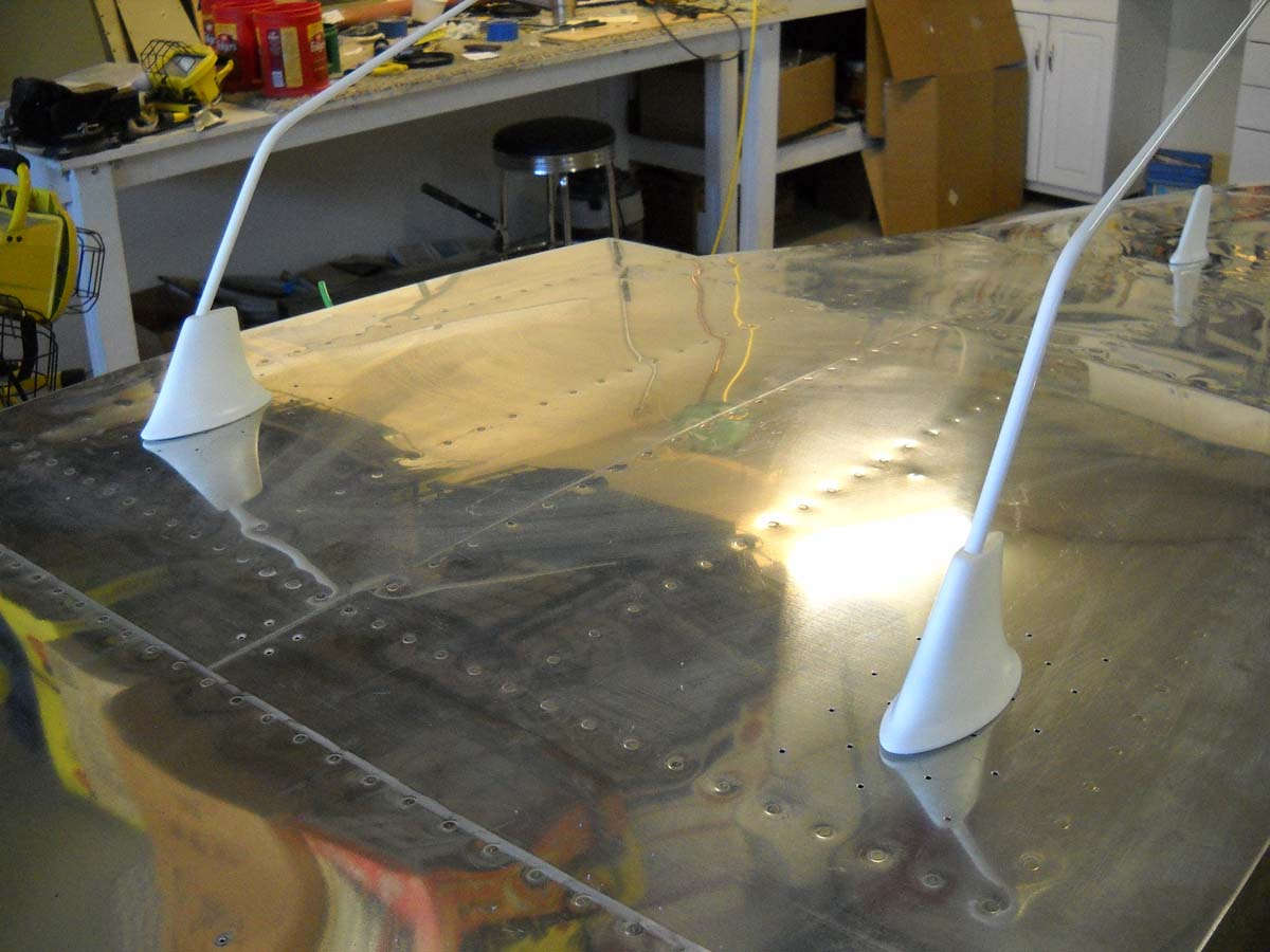
Another view of the two VHF comm antennas. I had a bit of a concern here because the GTN-650 installation manual calls for a second comm antenna to be mounted at least six feet from the GTN-650 comm antenna, which clearly is not the case here. However, a number of users have stated that mounting them this close, about two feet separation, has not proven to be a problem on the RV-8. We are betting on their experience.
A view of the inside of the fuselage where, if you look closely, you can see the antenna doubler clecoed into position with the RG-400 coaxial lead laying next to the hole where the antenna will mount.
And here is where the transponder antenna will mount. I considered this for a while on placement and decided this was best. It is slightly off center to eliminate any possible interference with the elevator push rod that is mounted above it.
And, here are the three Doubletree firewall pass through fixtures drilled and riveted into position. These will accept the three engine control cables: throttle, mixture and propeller. I plan on fitting those control cables prior to closing up the forward fuselage just to make the access easy.
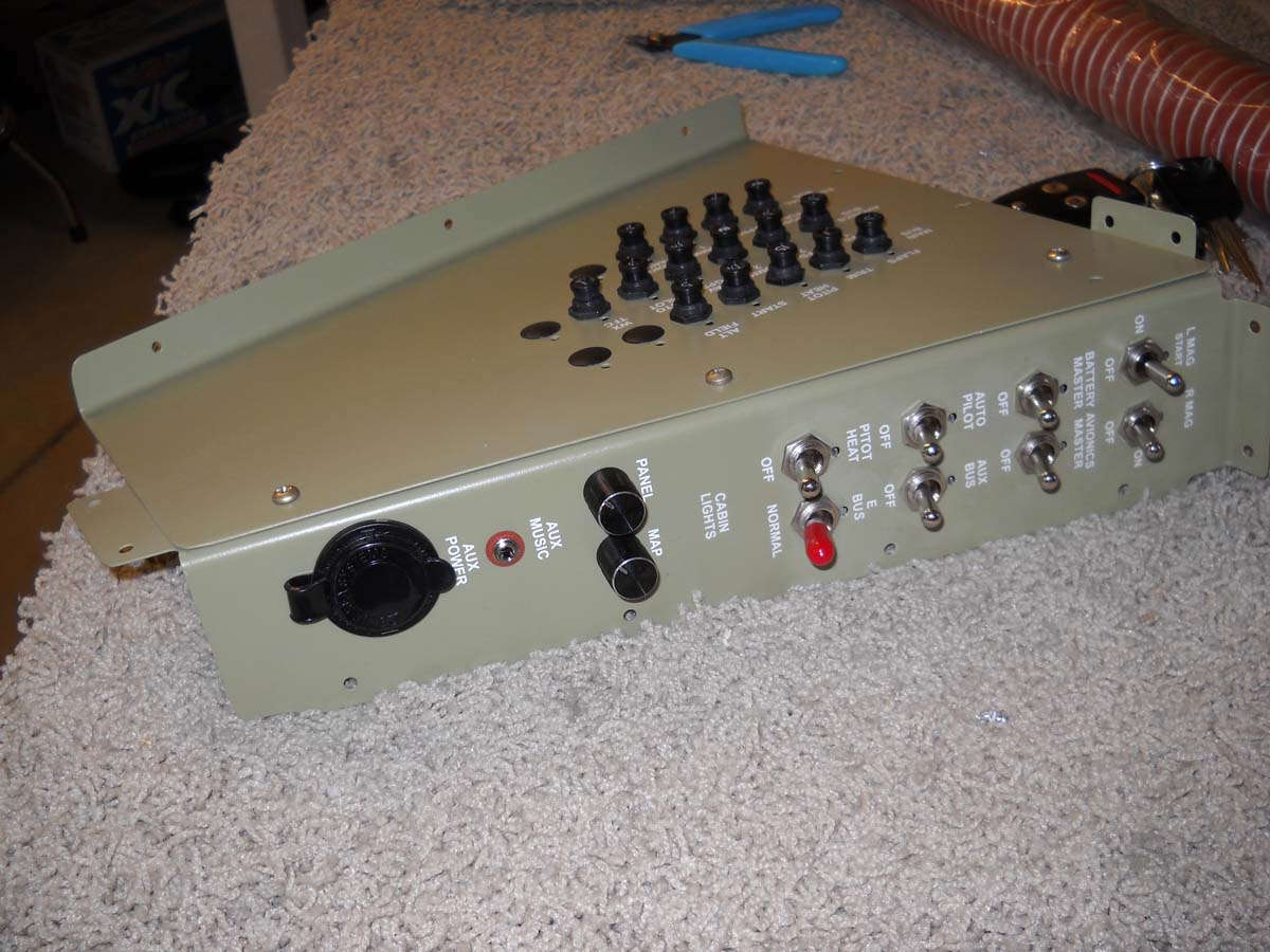
Back again to the circuit breaker and switch panel. I decided earlier to rework the location of two breakers and thus decided to redo the dry transfers that mark the breakers. That work was completed and switch breaker panels reassembled. Also, the panel lighting dimmer switches, an auxiliary music input 1/8" jack, and an auxiliary power recepticle were all installed on the aft portion of the switch panel. At this point I thought I was done and ready for installation.
Here is the other side of the breaker and switch panels awaiting the wiring from the airplane to be attached. The magneto/starter switch wiring is such that the starter motor cannot be energized without the left magneto switch being in the momentary "start" position but also that the right magneto switch must be in the "off" position. When I finalized the wiring for this I determined during some continuity checks that I really did not have the correct switch for the right magneto. I need a double throw double pole ON-ON type, so I had to order that for replacement.
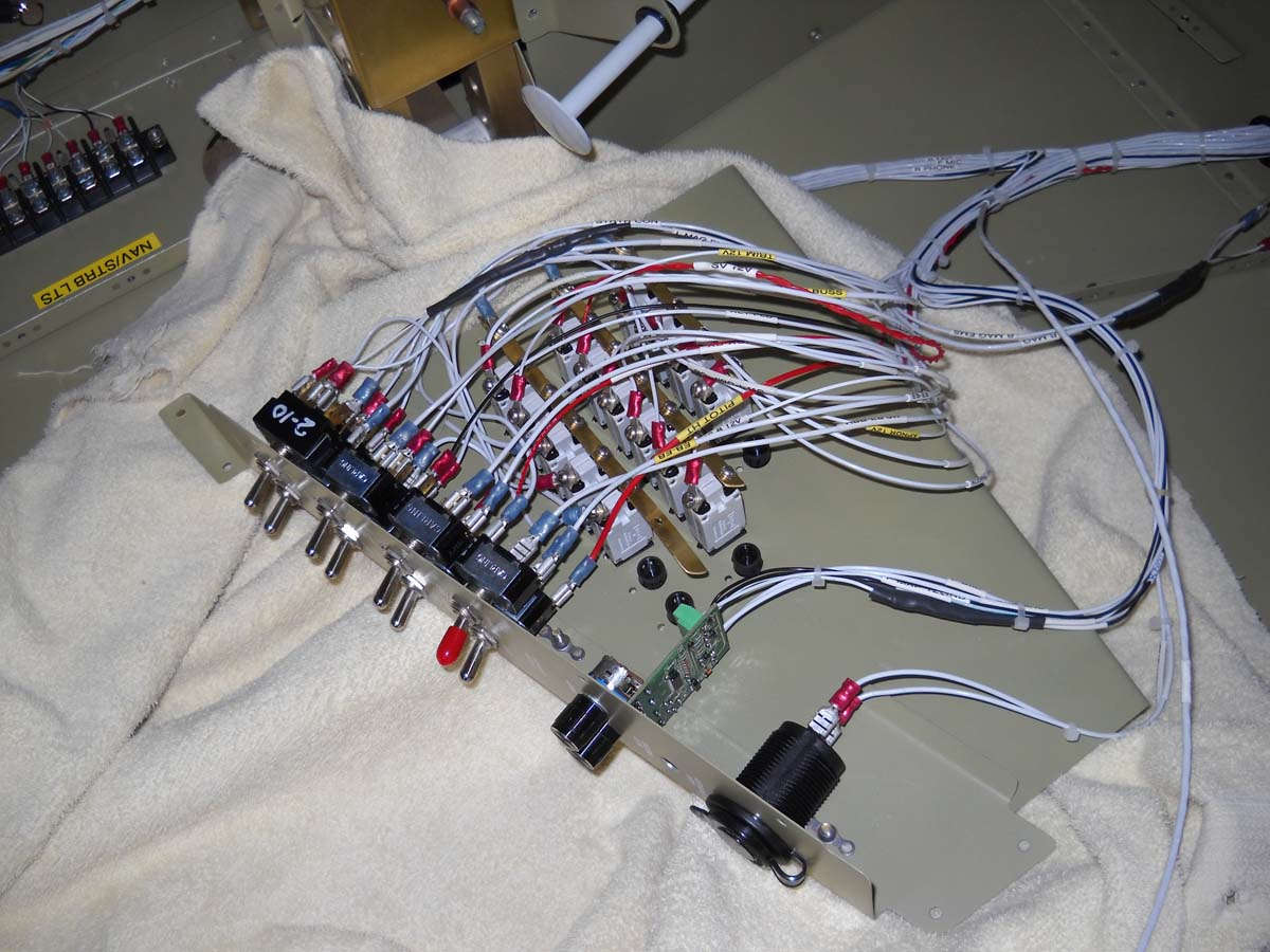
While waiting for that switch to arrive, I decided to go ahead and wire in the other connections and replace the magneto switch "in situ," as it were. Here is the wiring from the harnesses attached tot he breakers and panel switches.
And here it all fitted into position, very temporary since I need to replace the right mag switch, and also temporary because it will need to come back out a couple of times for the wing bolts. However, these wires will remain attached and the panel just moved out of the way for future access.
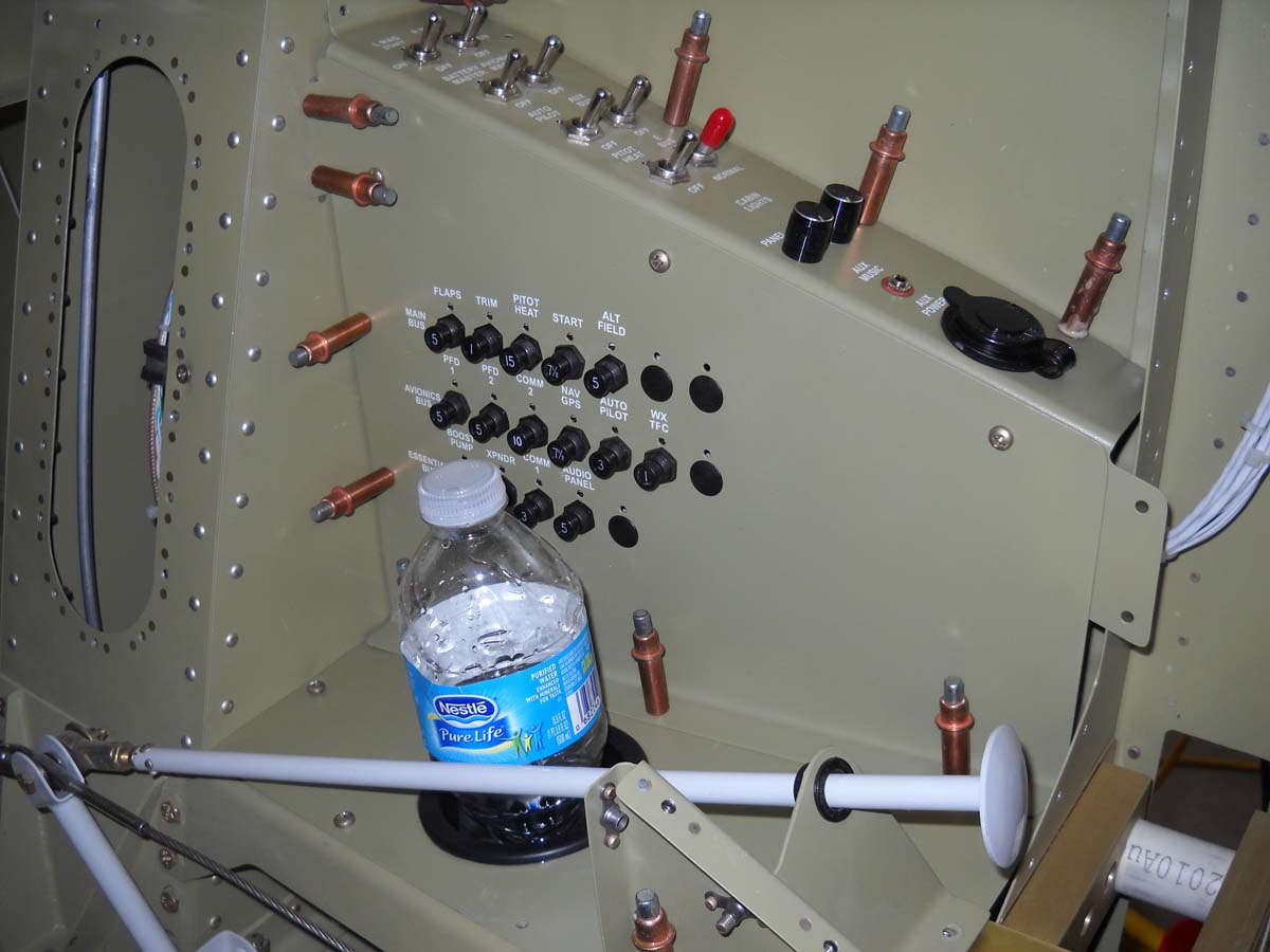
And, I have to point out my cup holder. I purchased the recessed holder from a marine supply store and cut a hole in the panel and epoxied it into position. I think it is a good location and should work out nicely. Just a convenience item but I really haven't seen this on other RV-8s. It seems a natural place for a cupholder. Go nature.
A wider view of the lower forward cockpit in its current state and getting close to its final state.
I was able to purchase a used but unused heated pitot tube/AOA sensor and control box for a bit of a discount from the Dynon offering, so it arrived in good shape and will be set aside for awhile for future installation.
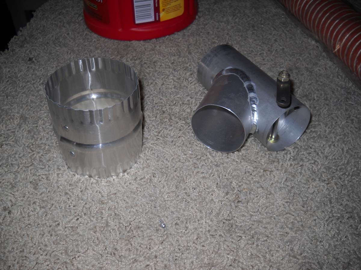
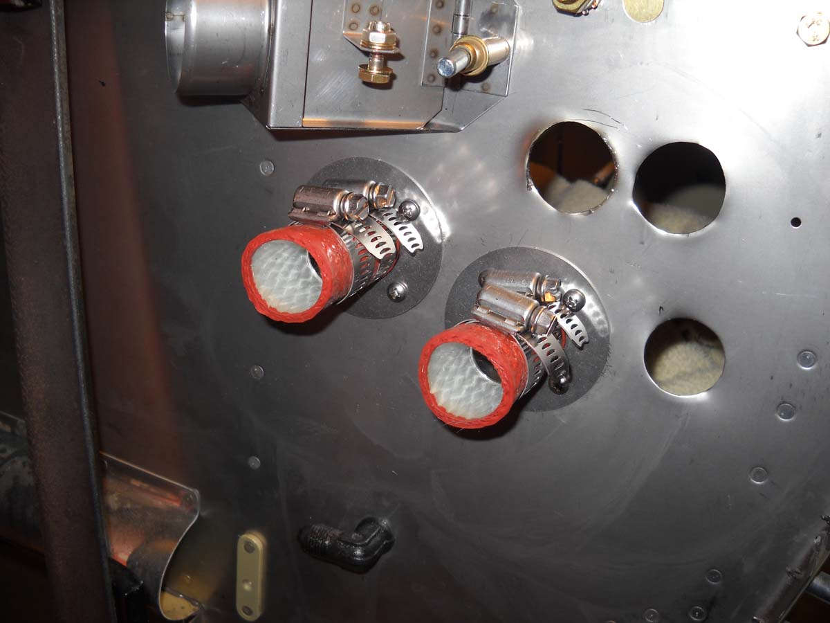
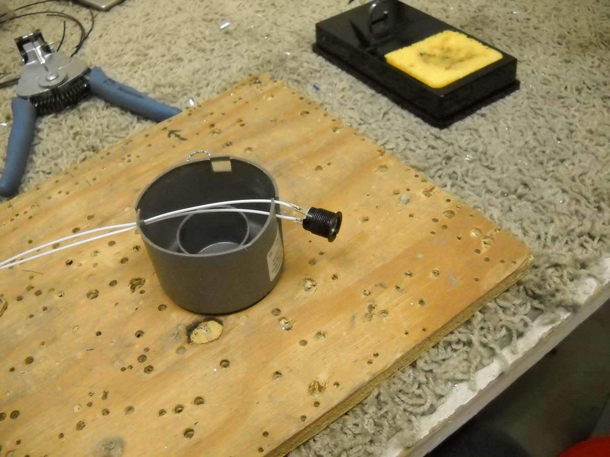
Okay, then, on to something different. As I wrap up the electrical I need to work out the fresh air/hot air vent sources. I need to connect the NACA style scoop to a heater valve. I was going to try scat tube but wanted something a little beefier. I found this 3" connector at Home Depot, held together with two rivets, so it was a fairly straightforward process to remove the rivets and trim it down to meet the 2" OD diameter of my valve assembly (purchased earlier at Aircraft Spruce).
And here is that assembly together. At the edge of the photo on the right is the exit from the firewall hot air valve, and it will connect to the valve in the middle. My plan is to modulate the temperature by using one control cable to close one valve and open the other, and vice versa. I need to make a couple of custom bracket to properly mount the control cable, so that is the next step.
Once these vents are completed, and then that magneto switch is installed, most of the work that I wanted to do before closing up the fuselage will be completed. Before moving to that stage, however, I plan to pressure test the brake lines and fuel lines, and also do some wiring checks.
April 16, 2013
In the last few sessions this past week I wrapped up the fabrication of the electrical system, a major milestone in my mind (anyways), and also did some quality control work prior to closing up the front of the fuselage.
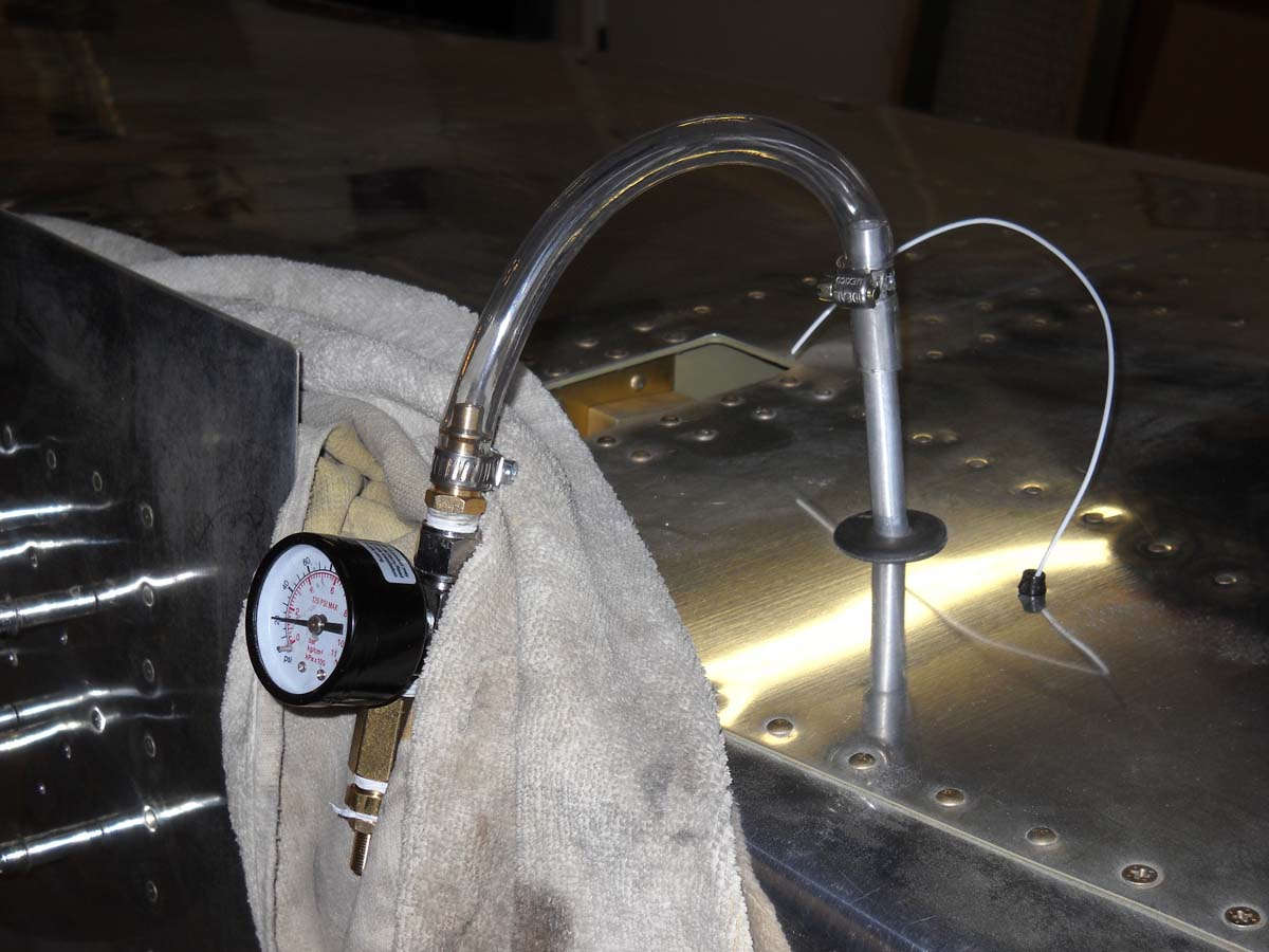
Starting with that quality control work, I pressurized the fuel and brake lines that run in the fuselage, one at a time, to ensure they are leak free. They were not but now they would appear to be.
For the fuel system, I plugged the firewall fitting and then applied a home-made apparatus with a pressure gage and a Schrader valve attached to the fuel lines coming to meet each wing tank and then pressurized the line to 20-25 psi. Eventually all the lines held the pressure.
It was essentially the same process for the brake lines running from the rudder pedals to the point where each of two brake lines exit the bottom of the fuselage on their way to the brake calipers on the wheels (someday, anyways).
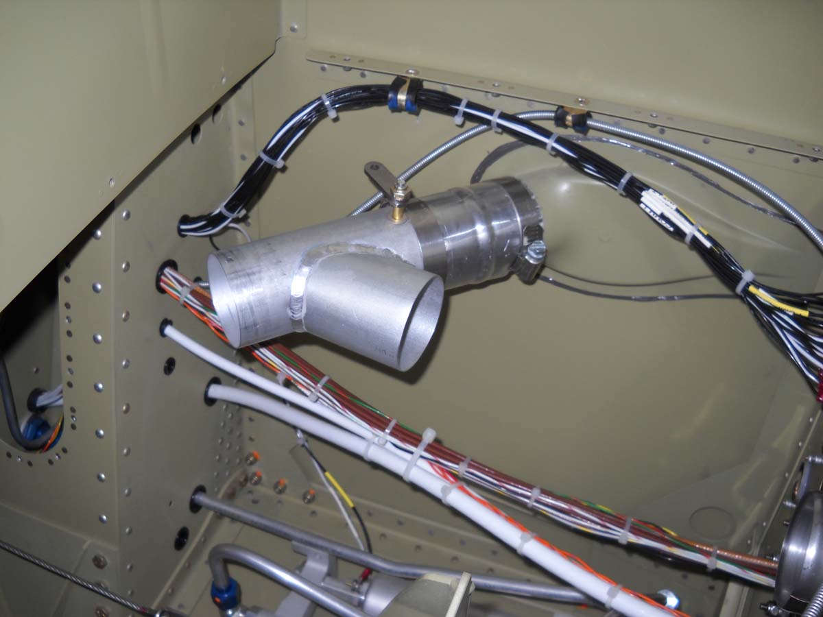
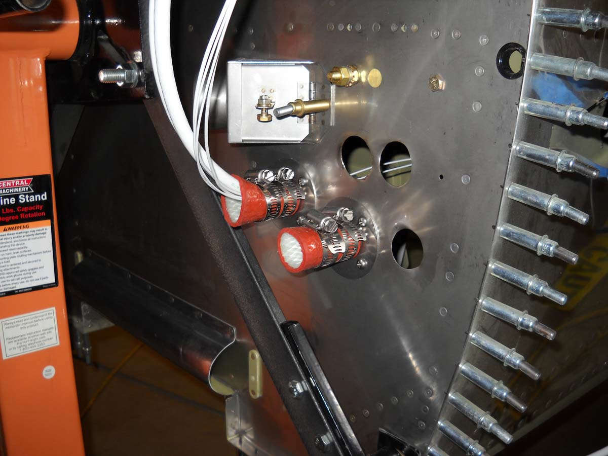
I also installed the air vent lines to supply hot and cold air to the cockpit.
Another view. With these scat lines installed, the behind the panel work is largely completed as far as I can tell, at least until the avionics is installed later.
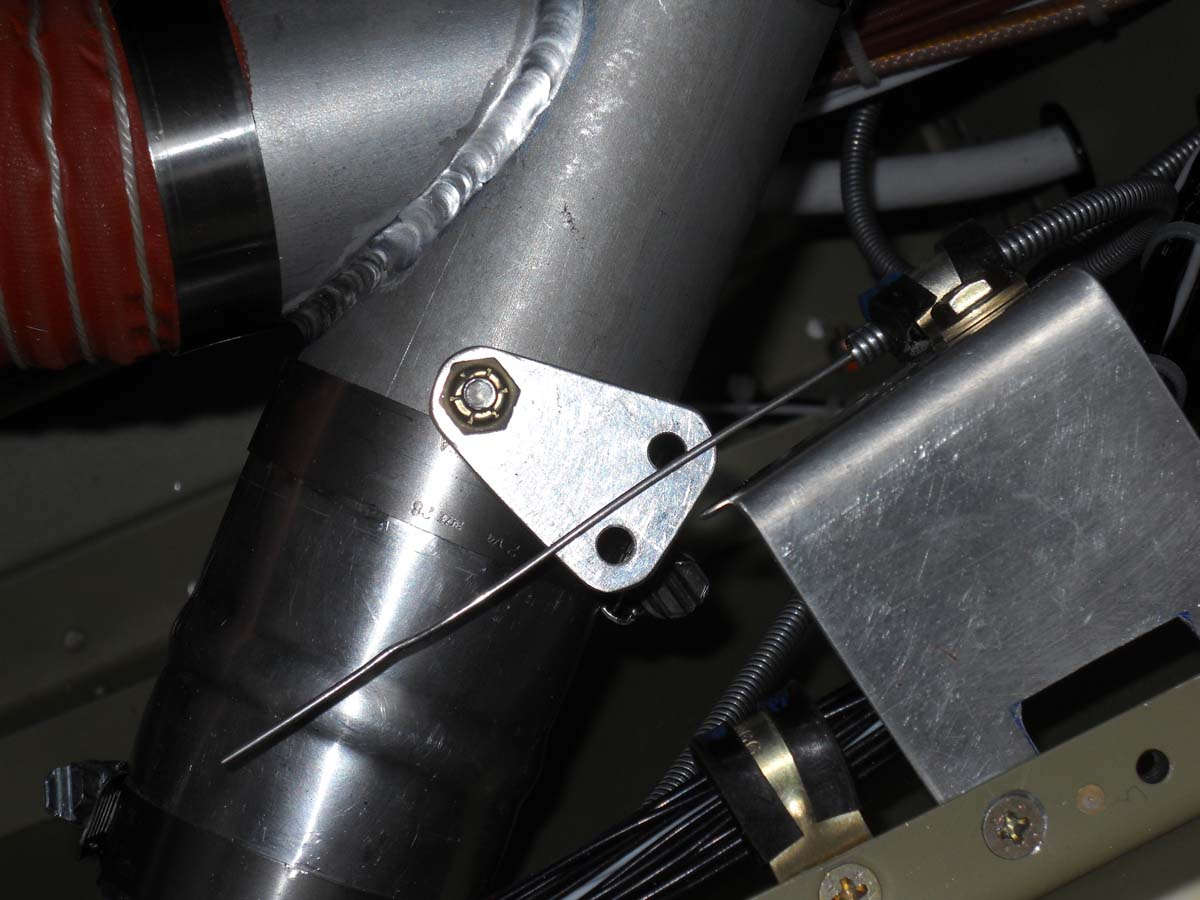
I had planned to use a "Y" tube as a mixing valve to control hot and cold air into the system. I modified the Aircraft Spruce heater valve to take this dual hole fitting that I fabricated to allow a single pull control to a) shift the air source to the cockpit from cold air (from the NACA vent) or hot air (from the heat box off the engine) and b), control the heat box valve mounted on the firewall. After some adjusting and rework, this has proven to be a good installation. Here it is with a bracket holding the control cable; this bracket was later discarded and redone to work better.
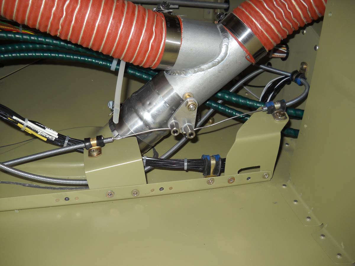
And here is the valve and wiring completed. I needed the cable attach points to pivot so I bought these a-bit-pricey special cable attach fittings to attach the cables to the valve pivot fitting. The cable on the right side is coming from the cockpit; when actuated it will shift the valve from cold air (coming from the fuselage intake) to the firewall heat box. The cable continues toward the left, goes through the firewall, and attaches to that heat box. It might help to orient if you know that the whole fuselage is rotated 90 degrees left so though this appears to be the bottom of the fuselage, it is actually the left side of the forward fuselage.
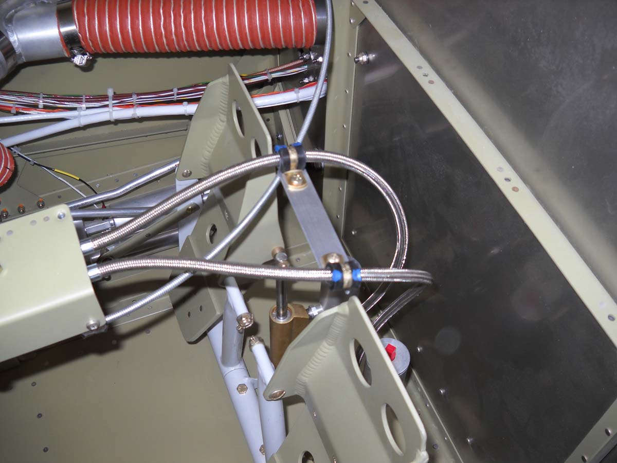
And, after testing the brake lines, I attached them to the master cylinders on each rudder pedal. I was not happy how they interfered with each other when the pedals were moved so I fabricated a piece of angle and two clamps to ensure some separation between the two brake lines. Should work just fine.
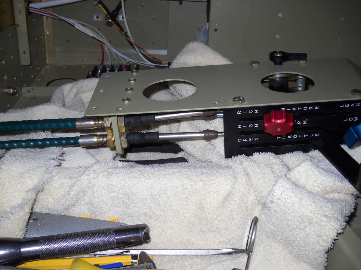
I installed the throttle, mixture, and propeller control cables. I decided this should and could be done before attaching the upper fuselage skin and I am glad I did. Inexplicably, the fabricated part that mounts to the throttle quadrant that holds the cables has different spacing than the holes in the gear tower that accepts the control cables. I have no idea how Van's thought that was going to work, but the fix required me to file the holes larger to an oval shape to allow the control cables to penetrate the gear tower. Took three times longer to fit these cables than I thought it would. Not too bad, usually these things take four times longer than I think they will.
The throttle quadrant with the cables being attached.
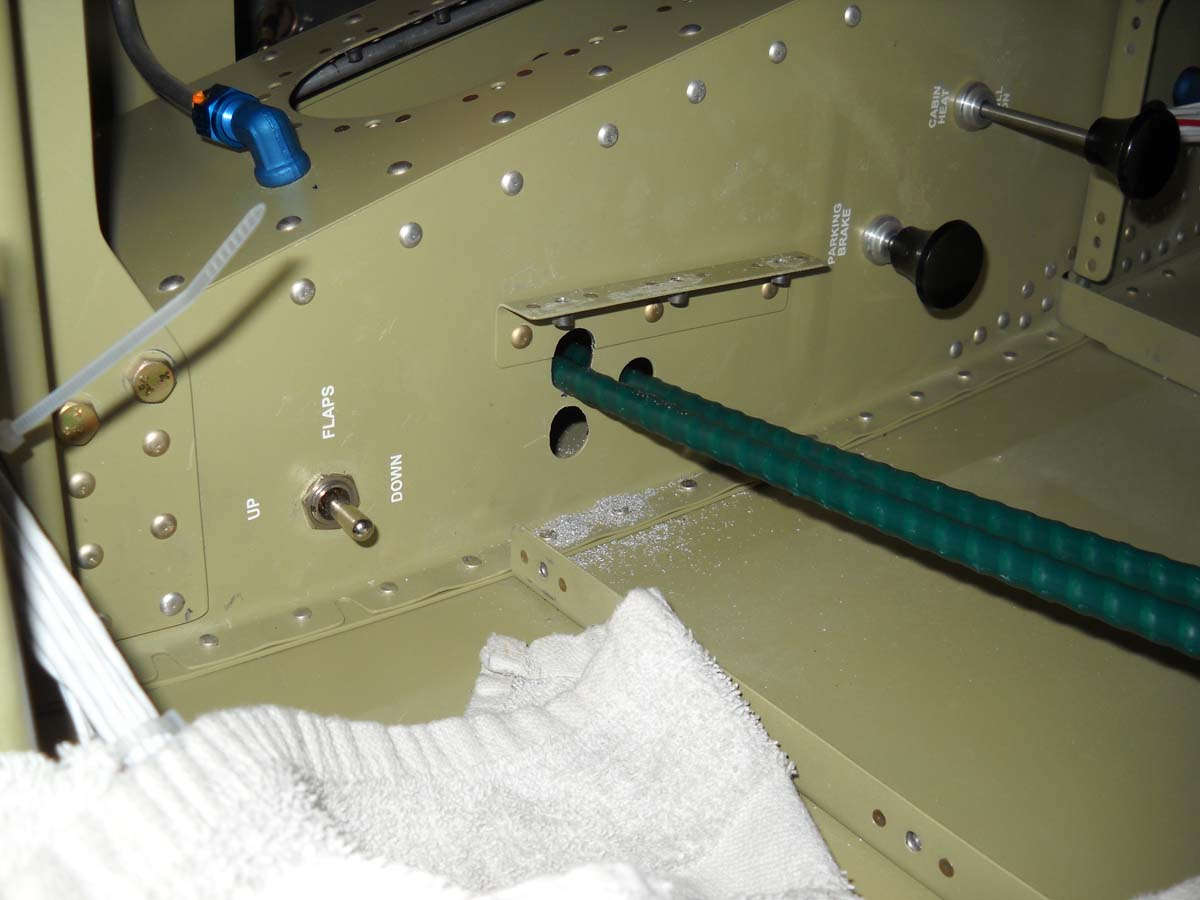
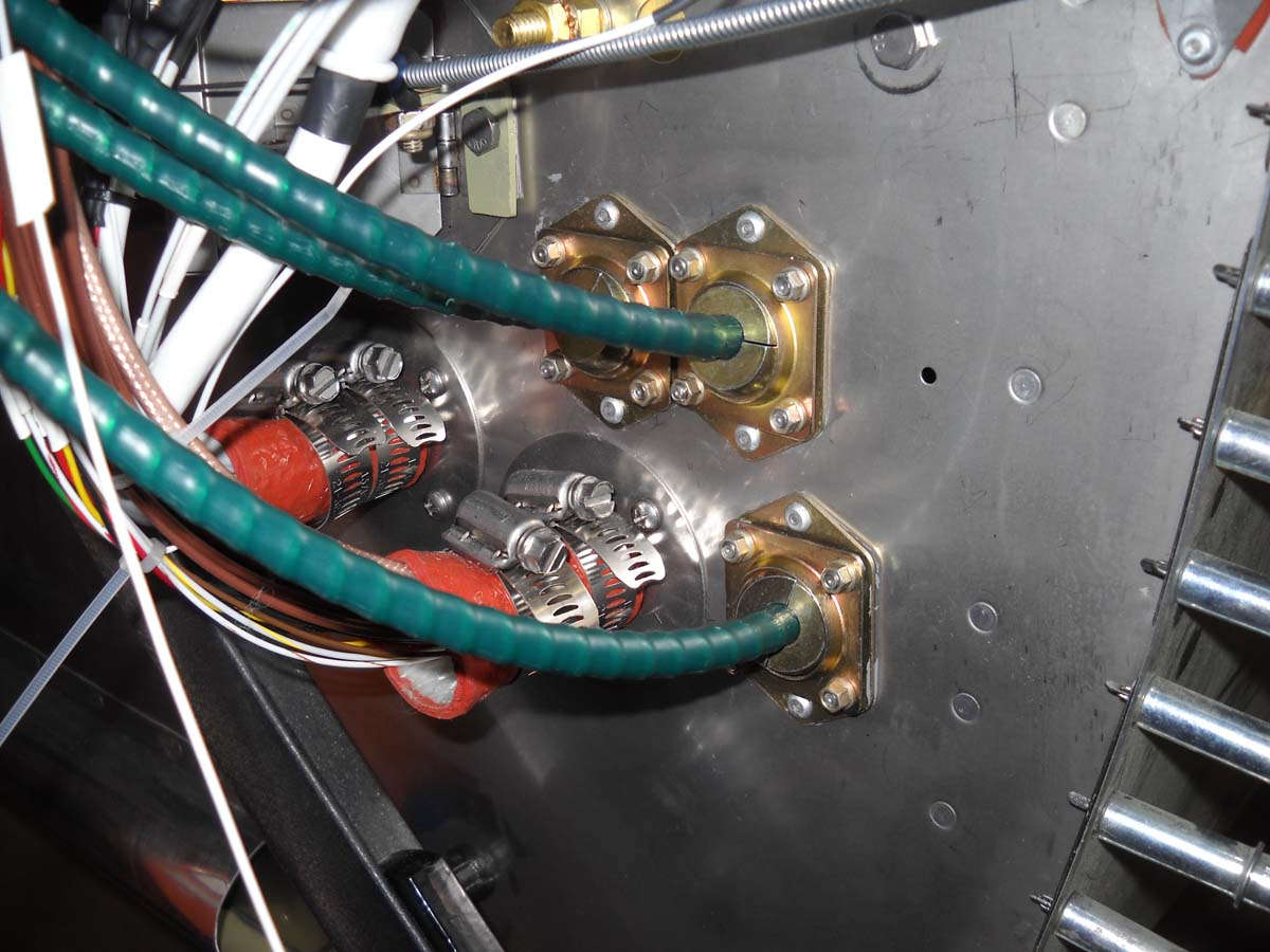
And the firewall pass throughs with the three cables secured. Not tightened down completely yet as that will be done after the engine is hung and the cables put into final position. But, I think, the hard work of mounting these three cables is complete. And, that cable coming across the top of the photo is that heater box control cable that mounts to the heater box valve.
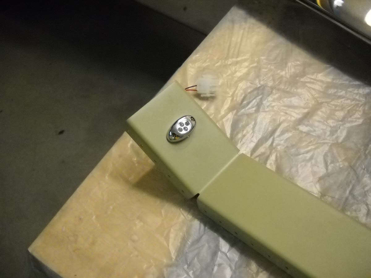
I installed this LED baggage light while I still had good access. It was only later that I realized that this might interfere with the baggage door part that accepts the latch pin. That part mounts in the two holes to the left of the light. We should be able to make it work.
And the back side of that forward baggage area LED light.
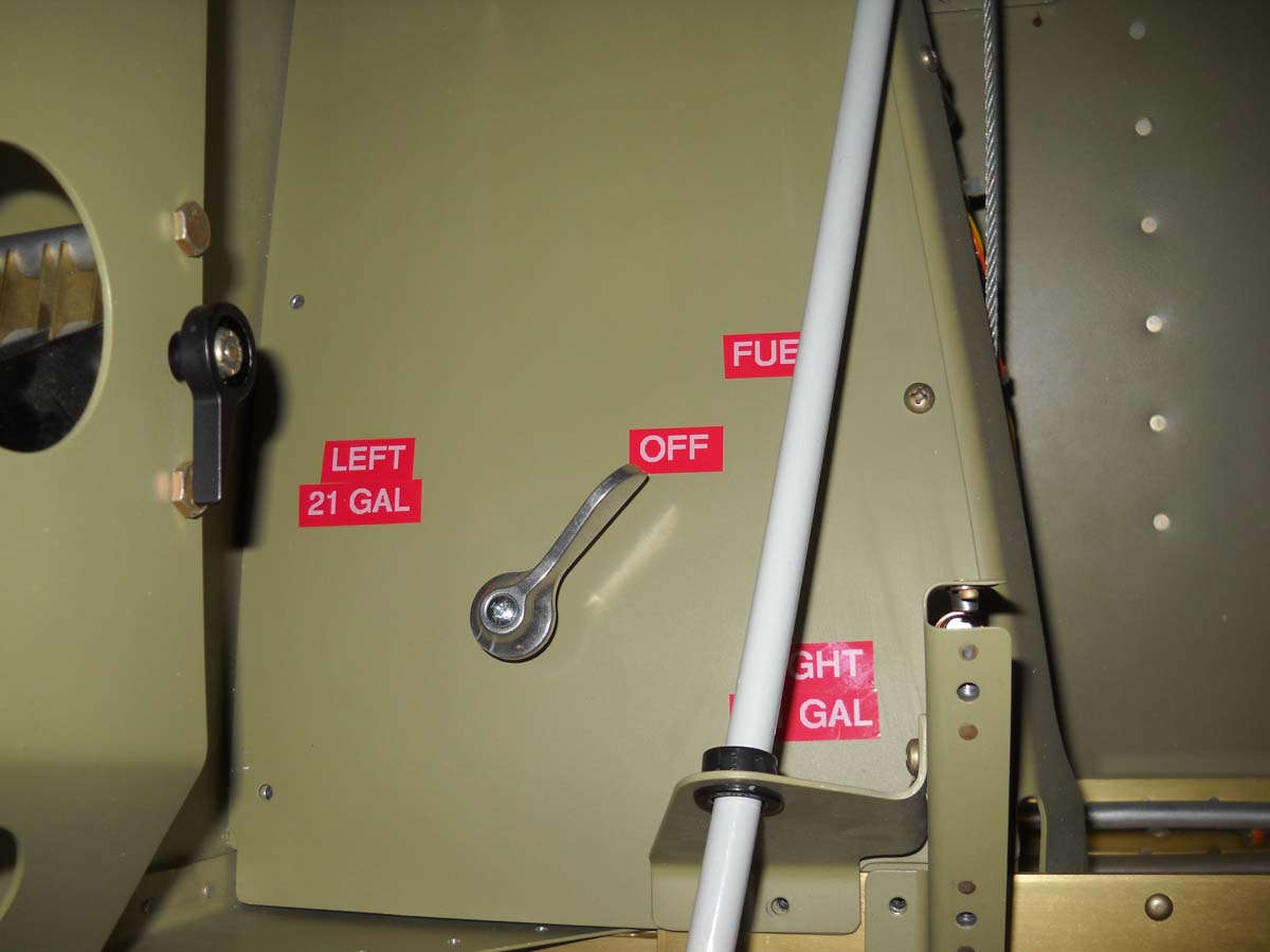
I decided to add the placards to the fuel panel and place it into position. Nothing fancy but it will work just fine. Simple; easy.
I spent an hour or two checking continuity and circuit logic and found more errors than I care to admit to. There were a couple of what I thought were errors also before I figured out that I had to disconnect the 2 AWG battery wire from the starter contactor to isolate the airplane circuits or else they would get power backwards through the wiring. This fact eluded me for a while but after I figured it out the circuits worked pretty much as advertised except for a few glitches, soon enough corrected.
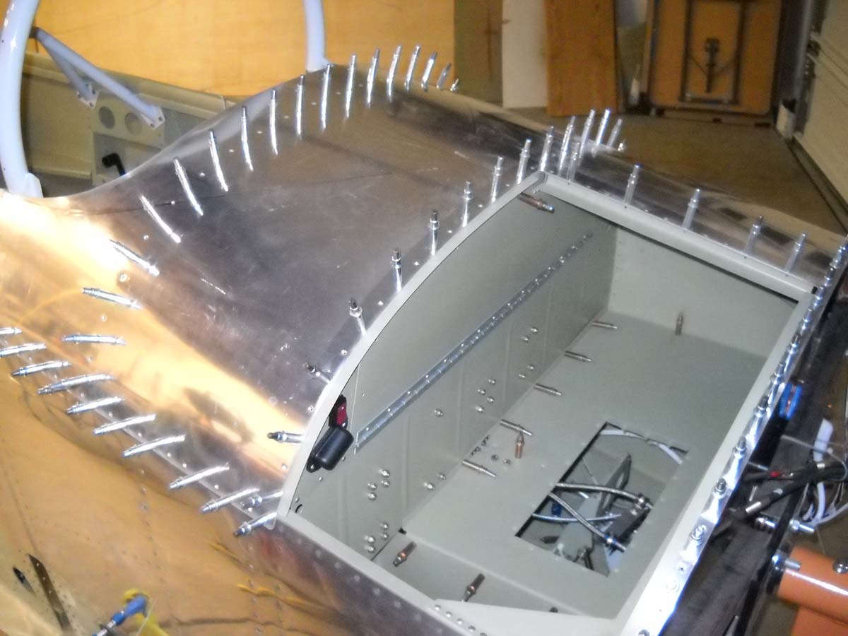
Finally, I thin clecoed on the forward skin in preparation for riveting it into position in the near future.
Another view of the forward fuselage with the upper skin in position.
And, one more.
So, in my mind, I am turning another page in this building project. With the electrical system completed and the forward fuselage closed up, I will turn my attention to attaching the windscreen and doing the fiberglass work for the frame around the windscreen. Something different and, no doubt, more challenges.
April 30, 2013
A major milestone for me this past week as pretty much the last structural rivets were driven to attach the fuselage forward top skin.
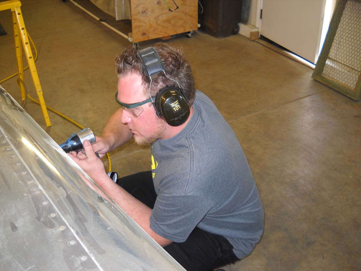
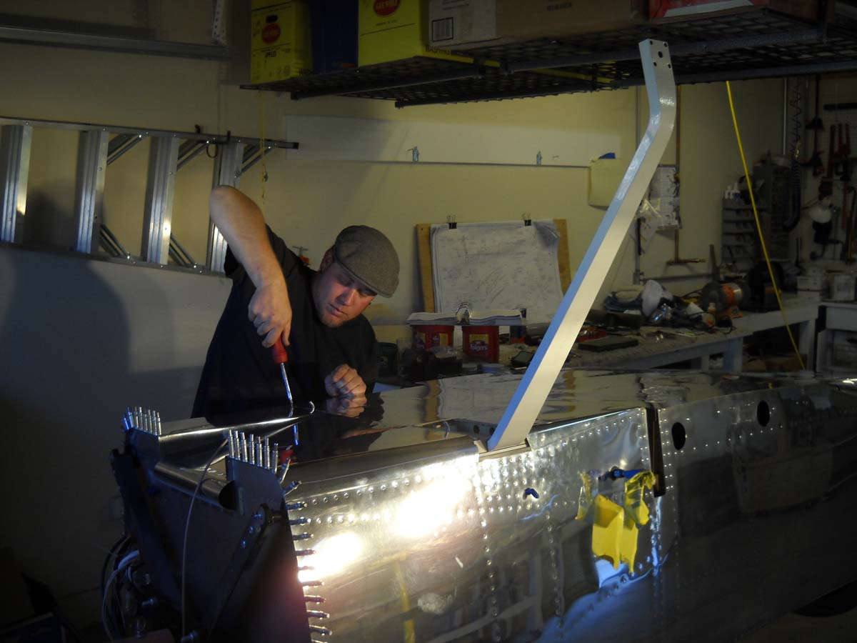
I called on one of my sons to help me with the riveting, this being Lucas who is handy with his hands and kinds of plods along figuring things out in a pragmatic way like his dad. Not a bad thing when building an airplane and he picked up riveting very quickly. Now I can happily say that all three of my sons have had their hands in this project.
So here he is as we are actually riveting the antenna doubler plates on the belly, something else we took care of during that session.
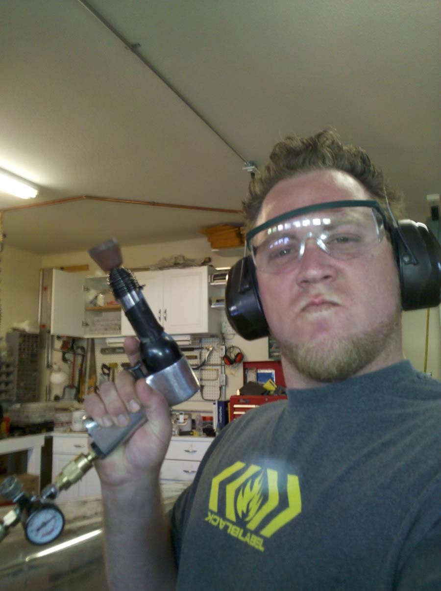
And here is the impressive dude himself. Not sure what to say about this. Don't mess with him, I guess.
And here is a rivet being drilled out. We had one bad rivet on the doubler plates, caused when my bucking bar slipped a bit while he was shooting. Not a big deal; drilled out and replaced.
Okay, and a celebratory moment after we completed the riveting. Cool.
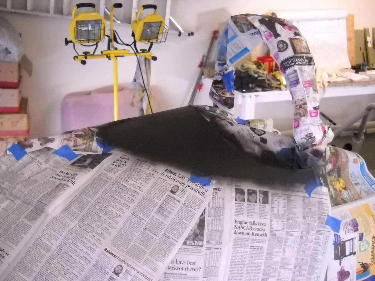
A few days later I moved right into the windscreen work. I read about what to do with the glareshield. Some guys use vinyl to cover the area under the windscreen. Some use carpet. Some go exotic. I went flat black paint. Simple and quick. I think it will suit the theme of the airplane...that is, spartan...just fine. Masked with plain newspaper...a no no in painting books...but handy and effective. A few coats of flat black and done.
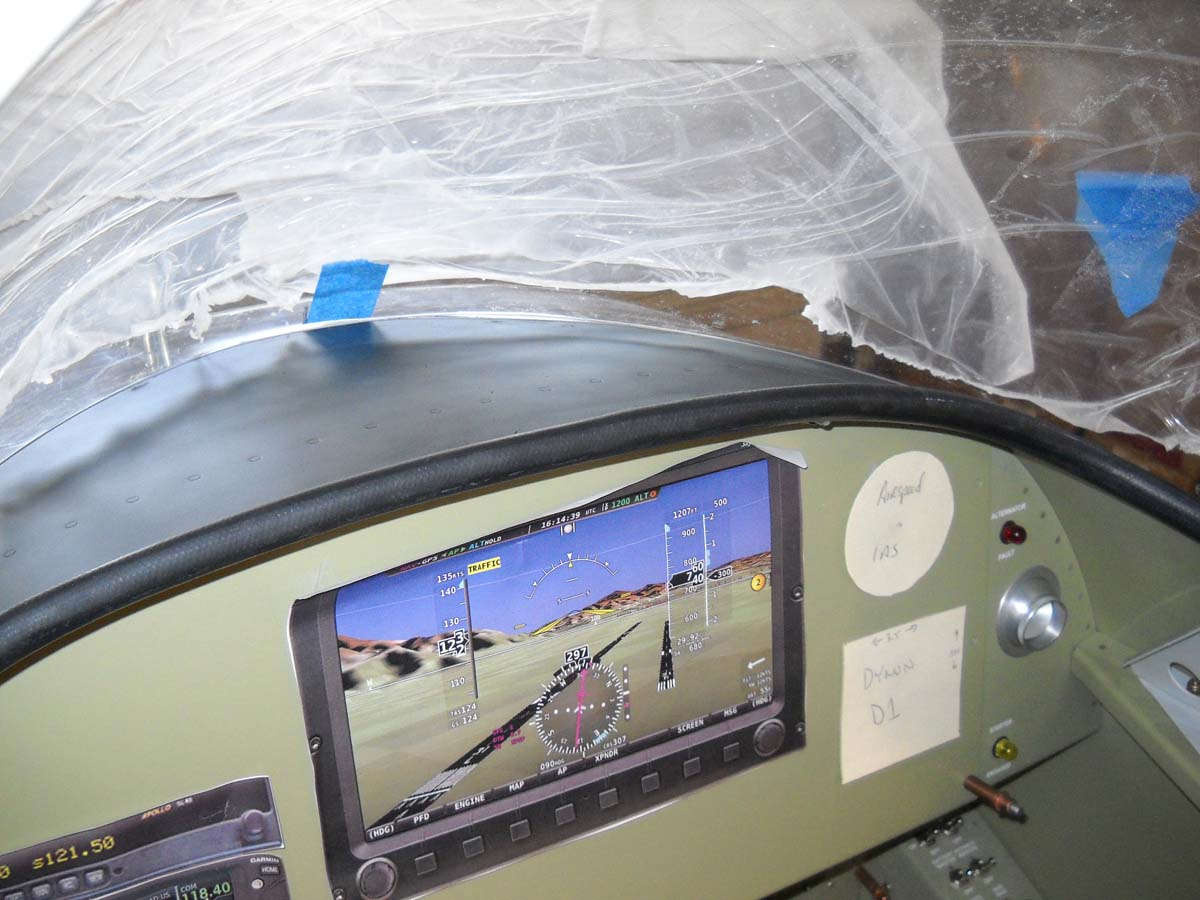
As for the sharp metal edge of the glareshield inside the cockpit? Again, I read about some different choices and how you can spend more than a few bucks here. I decided, again, to go spartan and slit a rubber auto hose and fit it on the edge. Looks good to me. I don't think I'll glue it. Seems to stay put on its own and I can remove it if needed to make the panel removal easier.
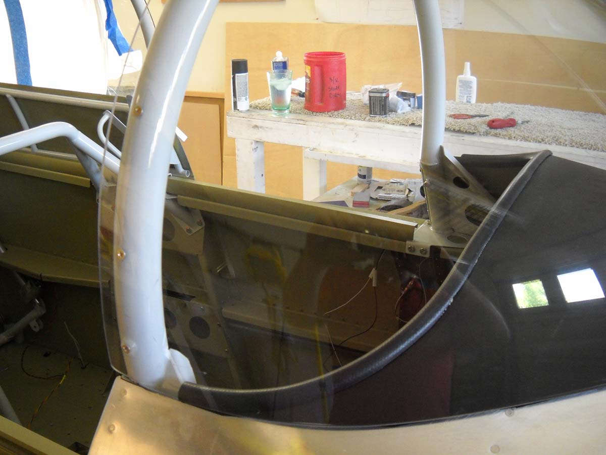
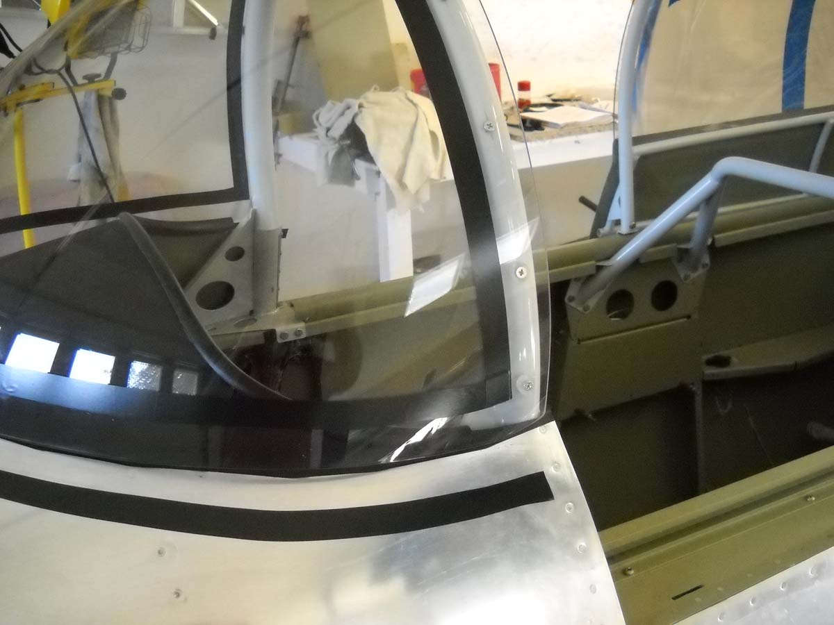
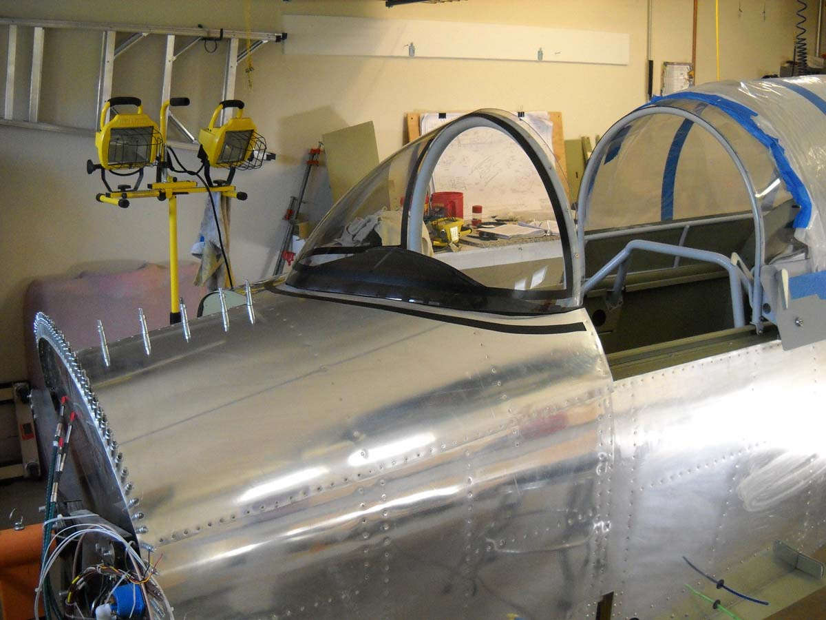
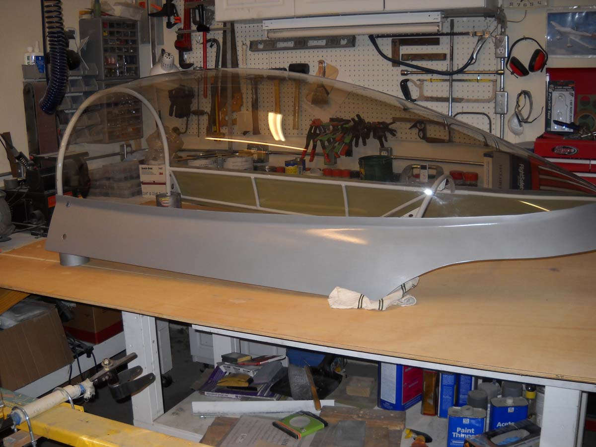
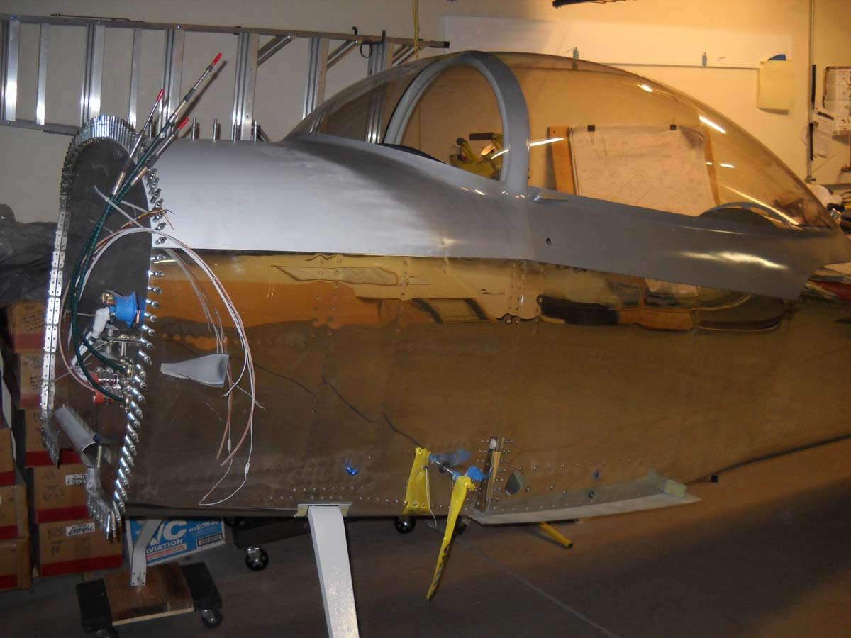
A few from the outside of the completed glareshield work. Flat black paint and the rubber hose. Also, as can be seen here, I have permanently screwed the windscreen to the roll bar. Used spacers on the lower few screws to help the windscreen meet the canopy. Not perfect but a starting point for the windscreen fairing.
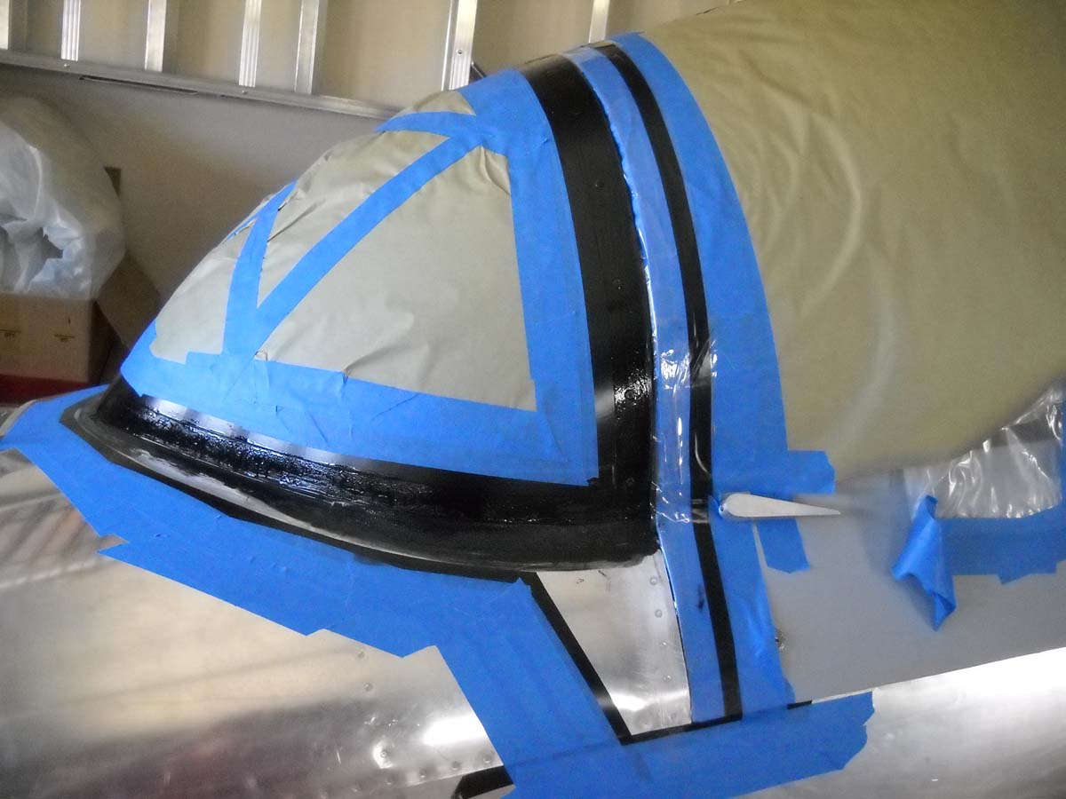
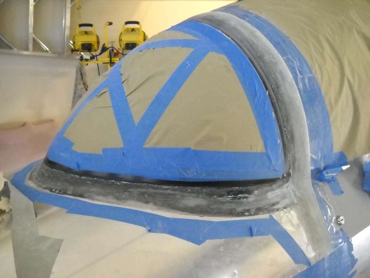
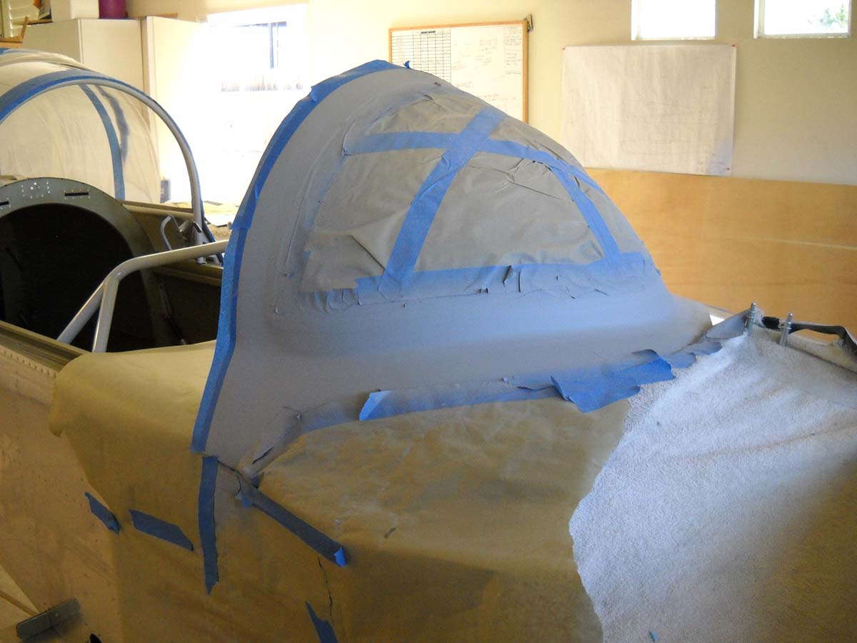
I read about the process of creating the windscreen fairing in numerous sources and pondered it for awhile. Eventually, though, you have to actually do something so I started to lay out the fairing with black electrical tape as per the Van's instructions. Seemed to be straightforward enough.
A wider view.
One bit of advice I incorporated was to start with a layer of dyed epoxy as the first layer. This will provide an even and better looking surface to be seen from inside the cockpit looking out. I purchased the dye at Tap Plastics and mixed up a batch and painted it on. I think it will need a second coat for better coverage, and then later will come layers of fiberglass and epoxy laid on top of this, sanded to form the fairing, and then finished with silver paint.
One fly in my ointment is that the left side of the windscreen forward of the rollbar does not lay down well on to the fuselage skin; there is a gap of, maybe, 3/8 of an inch. I thought I might be able to build this up with epoxy and microbubbles but, after trying an initial build up, thought better of it. I ordered some foam that I will use to seal the forward baggage door against rain entry, and use some excess foam, cut to size and epoxied into position, to close the gap and provide a good surface to build the fairing from. We will see how that works out shortly.
May 16, 2013
More work on the windscreen over the past two weeks, here and there anyways as I have been flying for work for part of that time. But I have done the major fiberglass work and am now to the finishing part of the process.
I noted last time that I had a pretty good gap between the windscreen and the fuselage just forward of where it meets the rollbar. I wish I had paid more attention to this area when I was fitting the canopy as this would have made this process easier. Nonetheless, I ordered some closed cell foam from Aircraft Spruce, which I wanted to do anyways to help seal the forward baggage door. I cut and fit a small piece of foam and epoxied it into the gap as a base for filler and that worked about as well as I could hope. I sanded it to flow into the curves. It is noticeable on the inside if you are looking for it, but otherwise the gap filled in nicely and I press on.
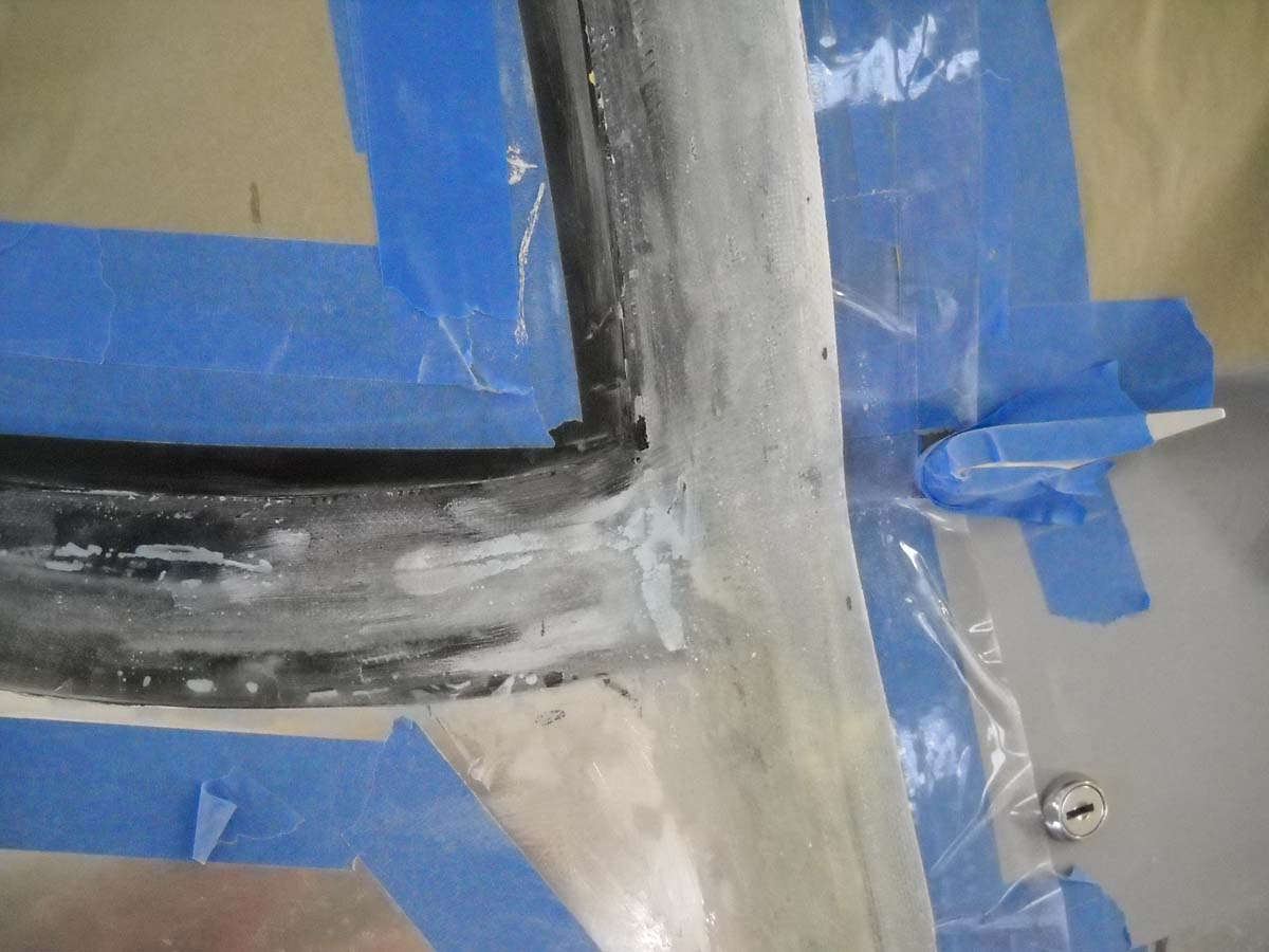
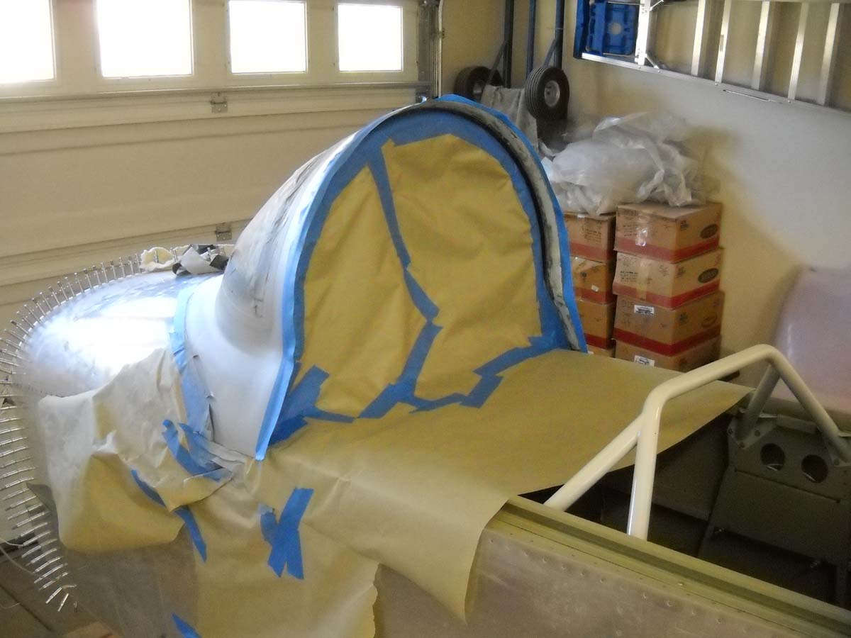
After I carefully applied two layers of vinyl electrical tape to mask the edge of where the clear plexiglas will begin, I covered the area with two layers of epoxy dyed black. I dyed the epoxy because the view from the inside of the windscreen will be of this expoxy as it lays on the outside of the windscreen, so I wanted it to look better than the clear layer of un-dyed epoxy. Worked fine.
Then, using the basic instructions in the RV-8 plans, I laid up layers of fiberglass. For the fuselage-windscreen joint, I started with a width of 1 inch and increased it with each layer to maybe four inches or so...can't really remember, but enough to bring the fiberglass up to the base of my electrical taped demarcation line. For the area over the roll bar I laid up successive layers that extended from my black electrical tape on the windscreen aft to cover the canopy-windscreen gap and then aft another inch and one half or so. Can't remember that one either. Anyways, it worked out well enough. After sanding a bit I thinned out the canopy layers a bit too much and added another two or three layers of fiberglass there to fill it in a bit.
This looks to be a mess but actually is not too much. I tried to make a nice curve where the windscreen fairing changes from vertical to horizontal, and also where it widens out to meet the width of the canopy to cover the gap. A couple of compound curves here that took some work. This is a photo from the middle of that work. I'm no fiberglass expert but one thing I figured out is that most errors can be readily fixed.
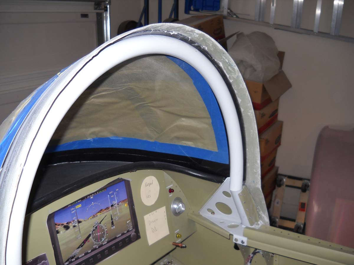
Another view after most of the rough sanding was completed. At this point I was not quite sure what I had for the windscreen-canopy thickness so I went ahead and worked the canopy so it would open for a check.
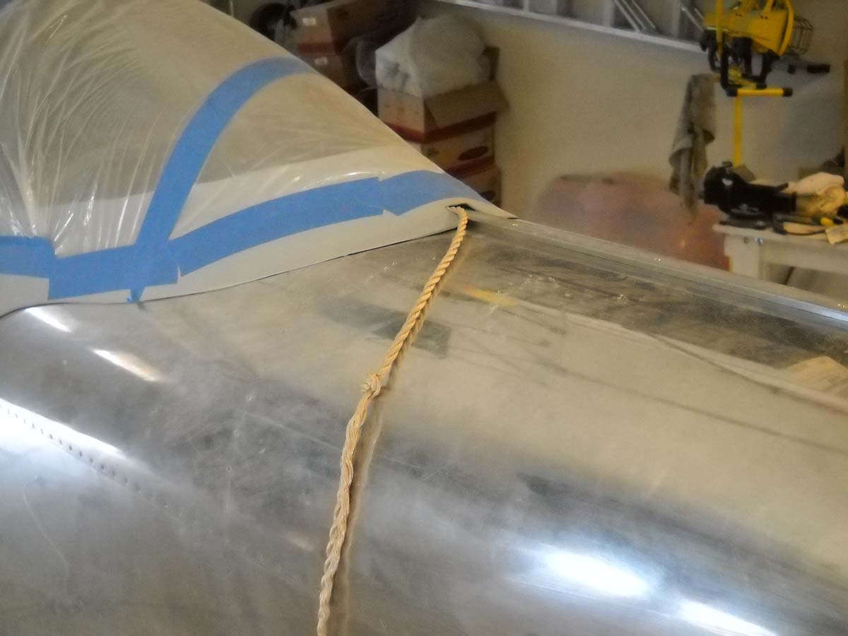
This rope idea borrowed from somewhere is essential in the process as far as I can tell. I am not sure what I would have done without this rope attached to the inside of the canopy frame to help me get it open.
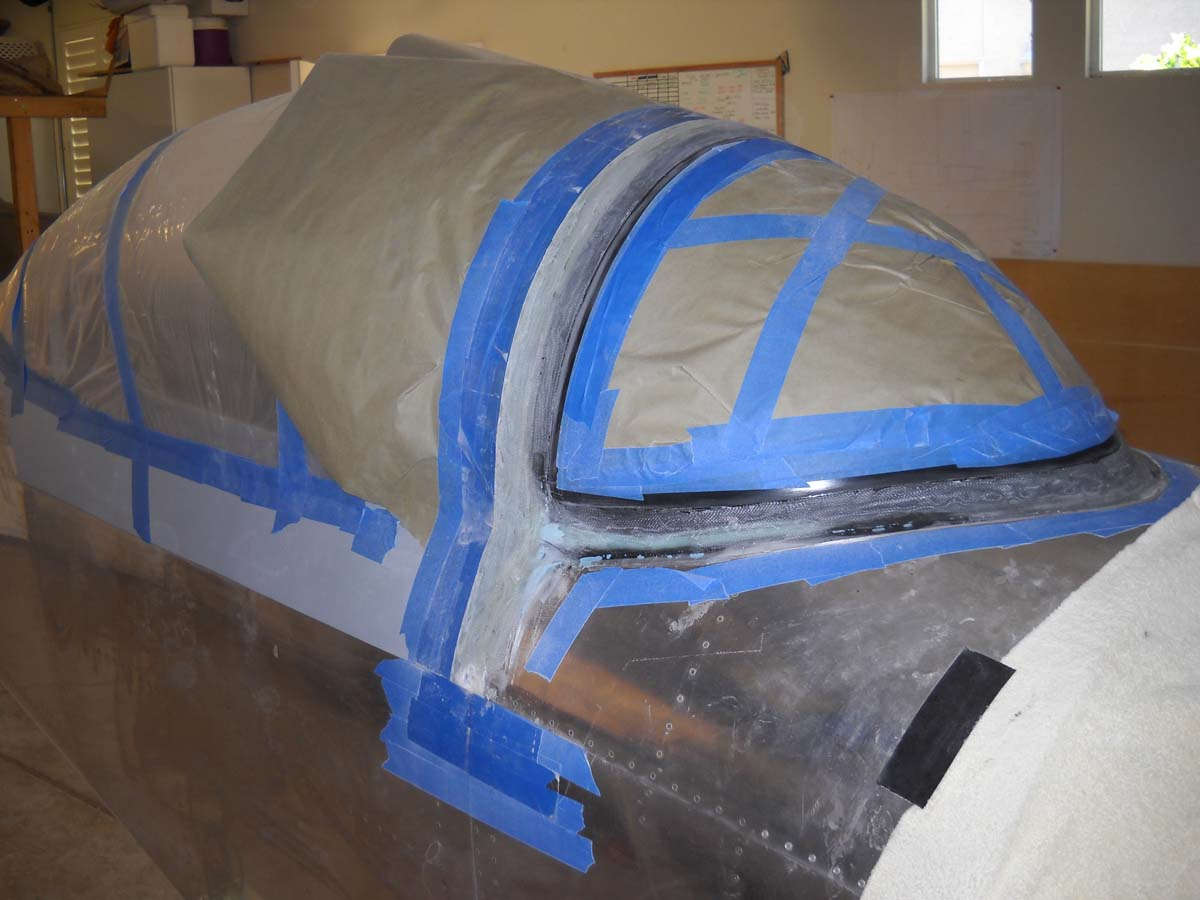
After trimming and a bit of sanding, this is how the fiberglass over the roll bar is shaping up.
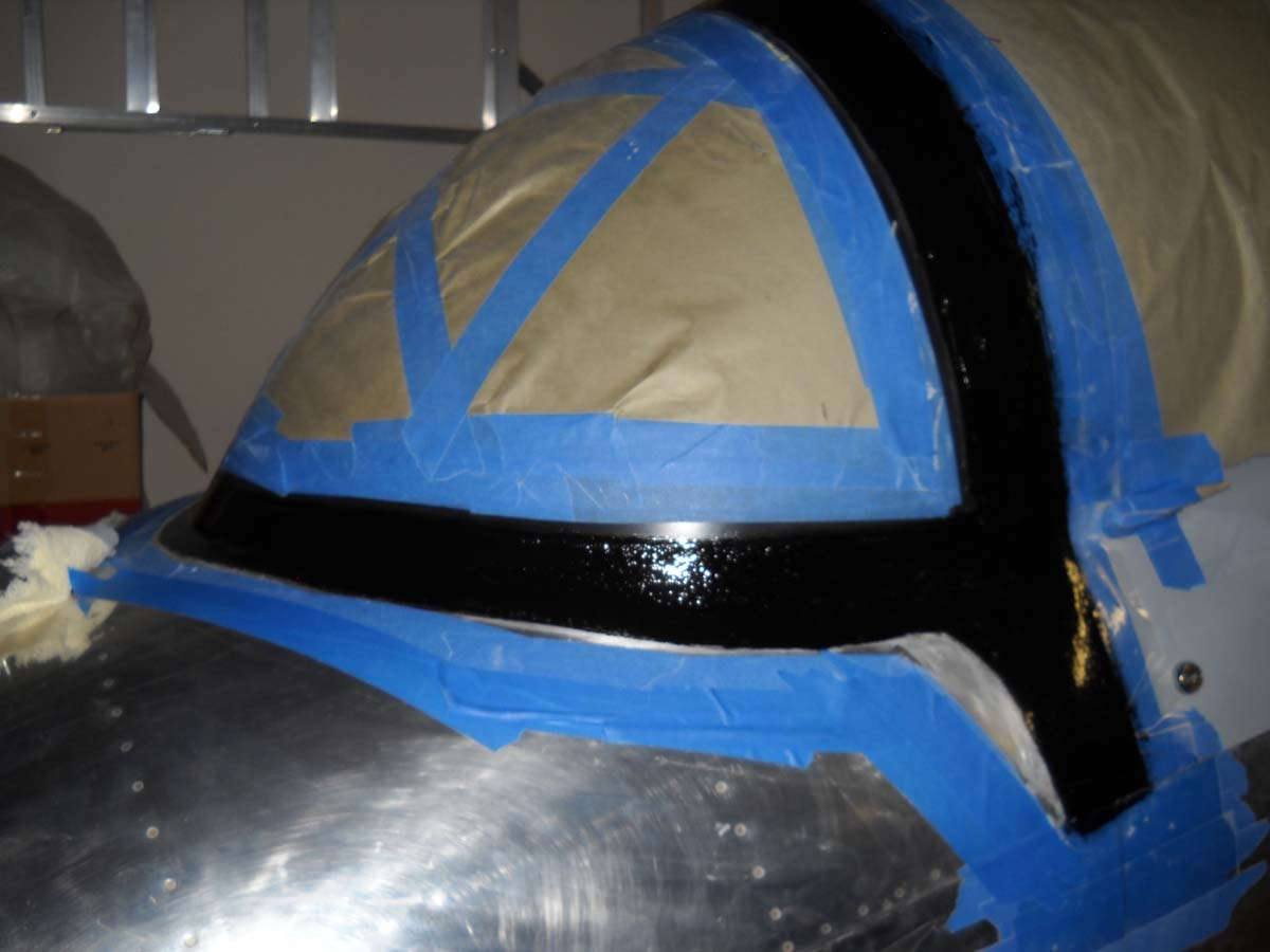
I did some more fine sanding to get the shape to where I wanted it and then covered the fiberglass with a layer of dyed epoxy. The next step is to sand this off as part of the finishing process.
I will do this several times to fill in the imperfections and get the fairing to just about the final condition. Eventually, coats of filler prime will be sprayed to make sure the imperfections are gone.
So, a few more sessions with the windscreen and this part will be nearing completion. The next big chore after this will be polishing the exterior. I am shortly to order material from Nuvite to move into this area. I expect dozens of hours of work to polish the aluminum, but that's okay. A labor of love, as it were.
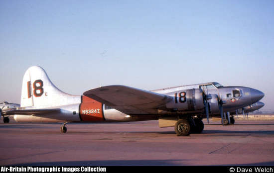
And, by the way, I jumped in to reserve a registration number for my RV-8. Henceforth, it will be known as N9324Z. Why this number? Well, in one of my other lives I am a B-17 historian, and I decided early on that this RV-8 would carry a discarded B-17 registration forward. The chosen registration was once carried by B-17G 44-83542 which, in its civilian life, was an air tanker operated by Aero Union at Chico, California. It was badly damaged in an accident many years ago and its registration was eventually cancelled. The airframe lives on as a museum display at the Fantasy of Flight museum in Florida. The registration number? It will live on marked on my RV-8.
I have a bunch of photos of this airplane in my files, but not near me as I write this. Dave Welch took this nice photo of
May 31, 2013
Well, the gist of it is that I pretty much finished up the windscreen during the past two weeks. I am satisfied with the end result and think it turned out pretty well and meets my own standard, which may or may not actually mean a whole lot. Nonetheless, I think it's going to work just fine.
Obviously, this process is a whole bunch of sanding and applying a new layer to be sanded off once again, mostly epoxy but a bit of filler here and there. Once I was pretty well satisfied I sprayed some filler primer on and worked some more to get the final surface very close.
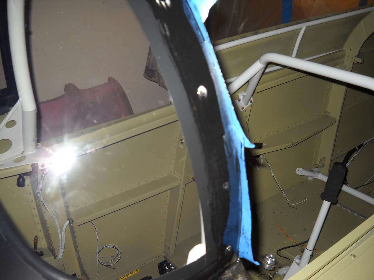
I then turned my attention to the inside surface behind the roll bar. It was pretty rough, not only in surface but also appearance. I sanded it smoother and added some filler to even the surface out a bit better. When it was what I wanted, I masked the interior so I could prime and then paint this surface.
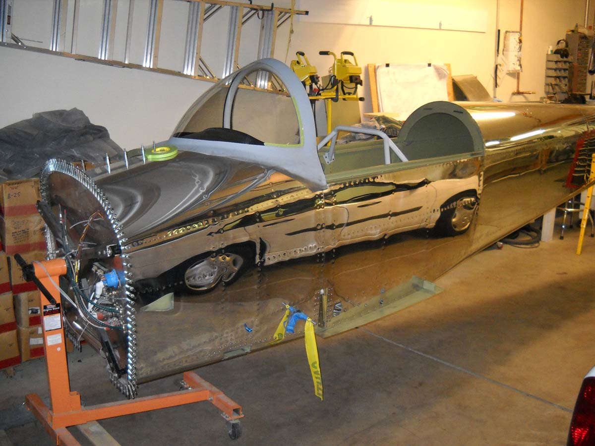
I've come to the conclusion that anyone who builds one of these airplane without a rotisserie is working harder than they need to. It has proven invaluable countless times to be able to rotate the fuselage around for better access and a more comfortable work experience. This was no exception.
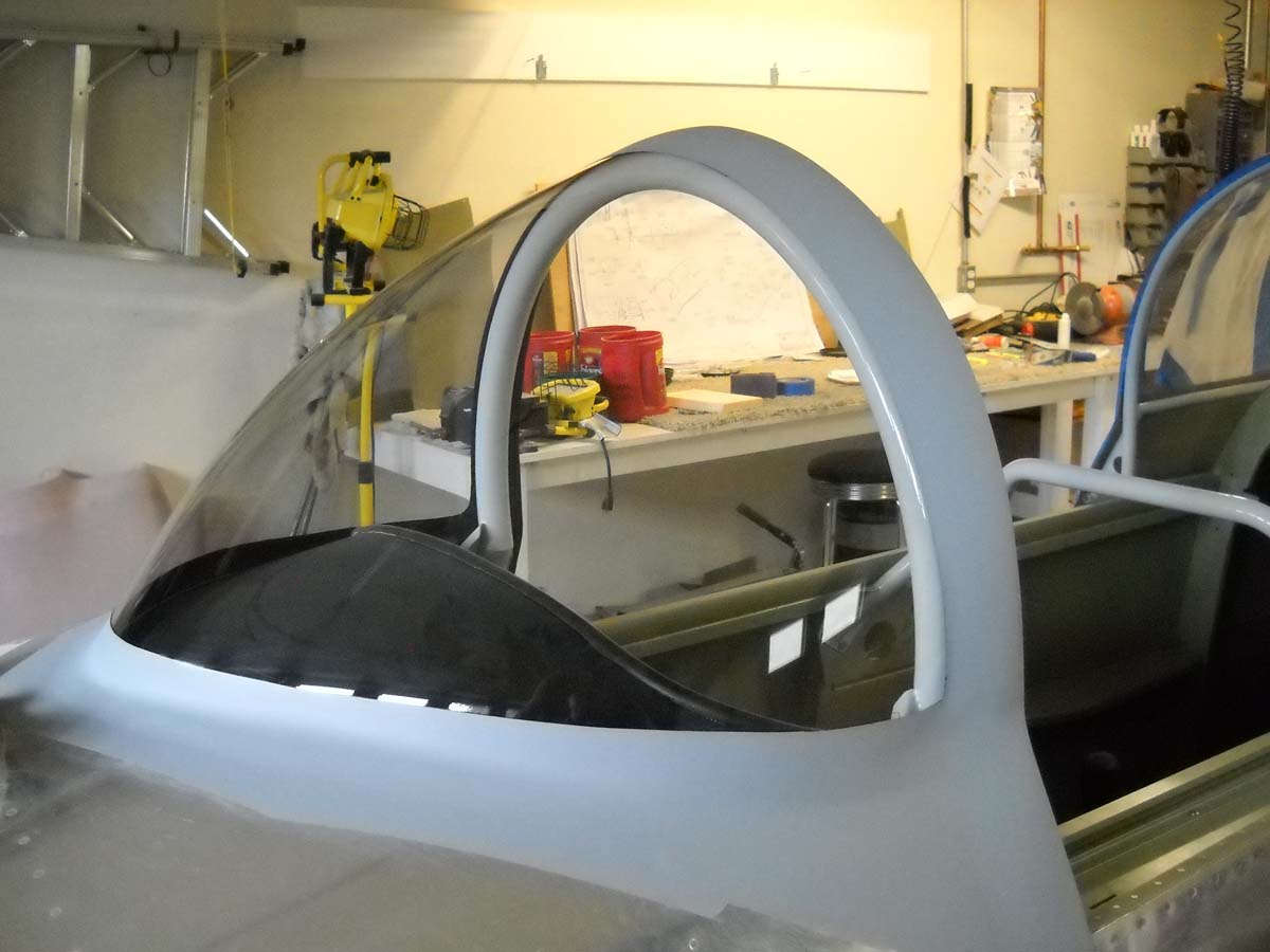
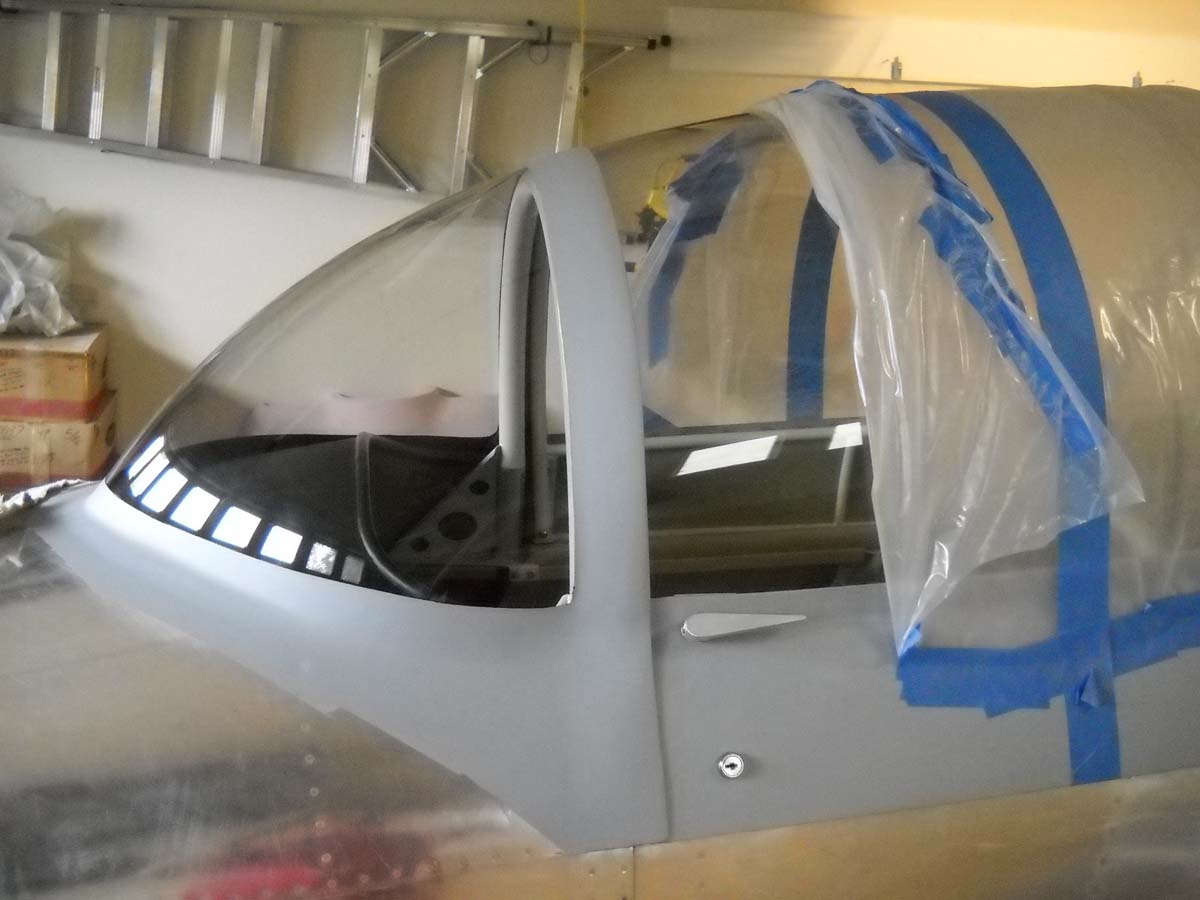
The unveiling was a bit nerve-wracking, not knowing what I was going to find underneath the electrical tape, masking tape, and paper. This was it. I had a bit of edge clean up here and there and maybe a flaw or two or three, but I will never tell. Looks pretty good to me and just about as good in person.
A view with the canopy cleaned up a bit and rolled closed. There are different ways to make this canopy fit with the windscreen but I am quite happy with this one, which I think is basically stock. I guess I am too.
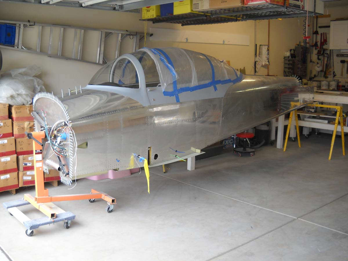
A summary view of the fuselage as it now stands, which is pretty much complete. There are a few odds and ends: flap positioning sensor and the odd such thing, but firewall aft is essentially done on this RV-8.
Next up: I'm going to become a metal polisher next and will start, I think, with the underside of the fuselage. I'd like to get the fuselage polished first so I can do some paint work on the windscreen and canopy, and also get the landing gear legs mounted. A few months out and this fuselage will lose the rotisserie (okay, a Harbor Freight engine stand) and stand on its gear for the first time. Maybe not wheels and tires, but up on its gear. Cool.
July 30, 2013
Hard to believe for me that it has been nearly two months since I updated this. Work slowed considerably due to several factors, among them being a delay in receiving the polishing gear I ordered from Nuvite, some personal "situations" that have developed, and an otherwise busy schedule.
With my Nuvite order, I had ordered both the compounding kit and the polishing kit in early June. Nothing came for weeks so I called and asked what was up, and was told that the kits were on back order. Good thing I called because nothing was forthcoming from them. Waited a few more weeks, actually until the third week in July when I called, again, and after some scrambling was told that half the shipment had shipped "yesterday" and that I would receive it "tomorrow", which I did, via next day air. The guy on the phone was nice enough, and they doubled my order of G6 and F7 gratis, and minimized the shipping cost. But, I am amazed at how hard companies work to get orders with nice websites and other advertising, and yet do so little follow-up with customer service. If I had received one phone call or one email, just one, about the status of my order after a month of waiting, I would now feel differently about the company. From what I have seen so far, they make very good products, but customer service is pretty iffy. I cancelled the rest of my order because even after all that, the polishing kit was on indefinite back order and they had no idea when I might get it. Why bother. I switched to PerfectPolish and they had what I needed in stock and it was on its way to me the same day I ordered it.
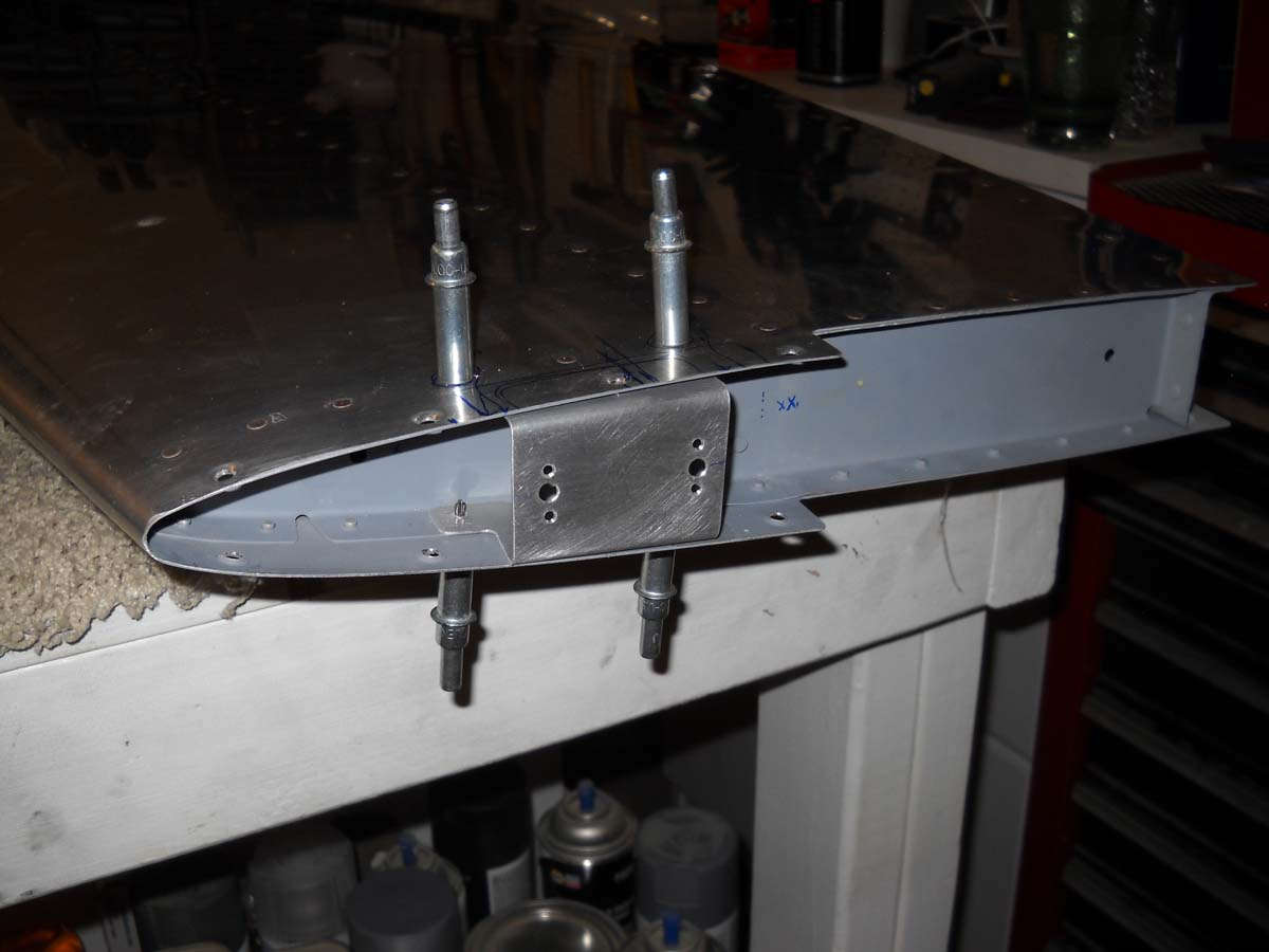
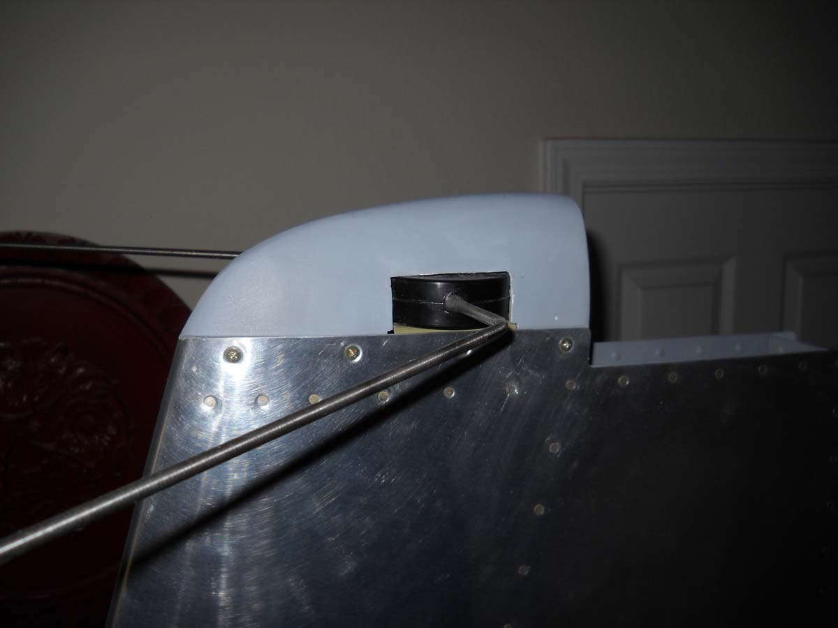
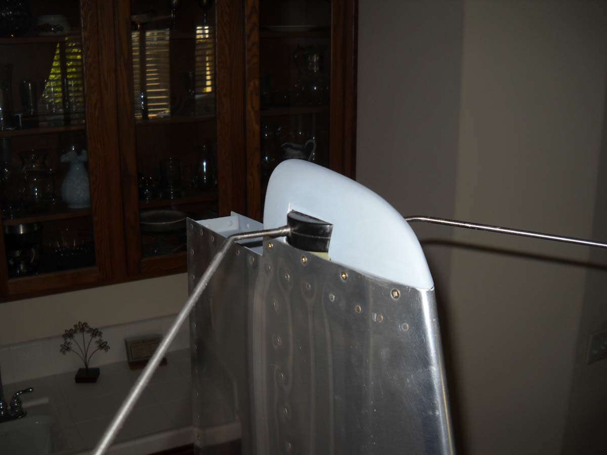
Enough on that. I did a bit of work here and there in the meantime while I stared forlornly at my front porch waiting for Mr. UPS man to bring me polishing things. I fabricated the bracket to hold my VOR/LOC/GS antenna on the vertical stabilizer, and set up the antenna mount for the still-to-come permanent installation. The old cat whisker antenna is probably not ideal from the looks department, but my instincts and some user reviews of different antenna possibilities suggest this is the best IFR type installation for me.
Different ways to skin a cat, as it were. My idea was to fabricate a bracket that would mount onto the top of the vertical stabilzer that would accept the antenna. I drew up a template of what I thought would work, transferred that to some heavy carboard bent up for fit and adjustment, then transferred that to aluminum. Drilled and bent, deburred and finished, this is what it ended up as.
And, mounted on the top of the vertical stabilizer. You will note it is forward of the counterweight of the rudder.
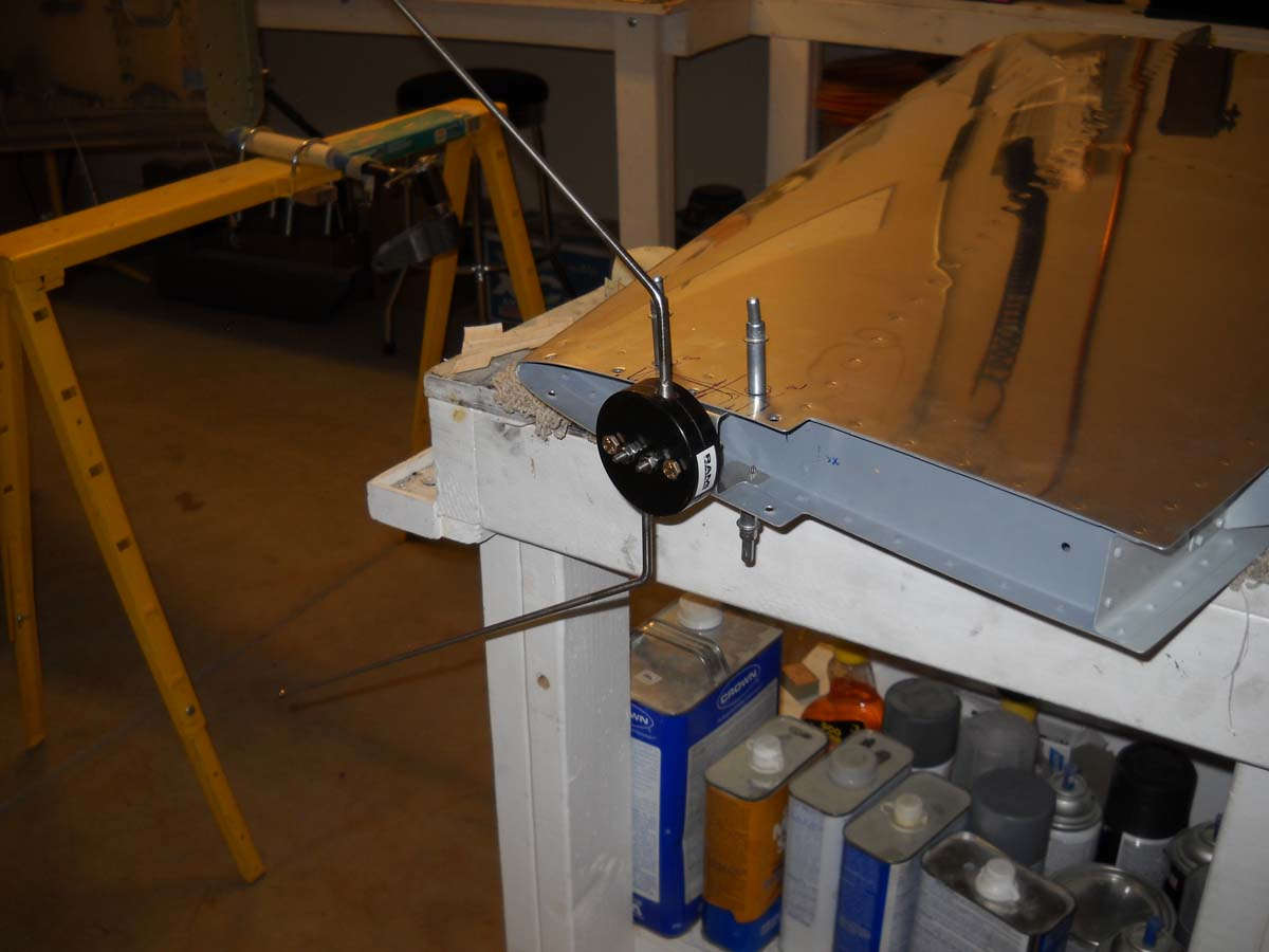
And the antenna itself mounted in position. It can be mounted with the elements facing forward or aft. It will probably end up forward to keep folks from putting their eye out.
A view if the whole thing done with the fiberglass tip cut down to accept the antenna.
And another view. This single antenna will serve for the VOR/LOC and the glideslope via a splitter that is used on the GTN-650 just, it turns out, for this purpose. Now, if I can just get this flying before all the ILSs go away. Just joking there, by the way. I suspect that long after I retire from my job, there will be new ILS installations going on. Good basic navigational system that suits high volume airports with predictable air carrier traffic flows just fine.
On to another little job: drilling of the pitot mast to accept the pre-drilled, slightly used heated pitot tube/AOA sensor I purchased last year. I had to carefully match the drilled holes in the pitot assembly to the proposed holes in the mast; worked fine. I also installed the pitot heat controller box in the wing, and that turned out to be a bit of a bear in the tight space I was working in. Done and done, though, at least until I apply power later.
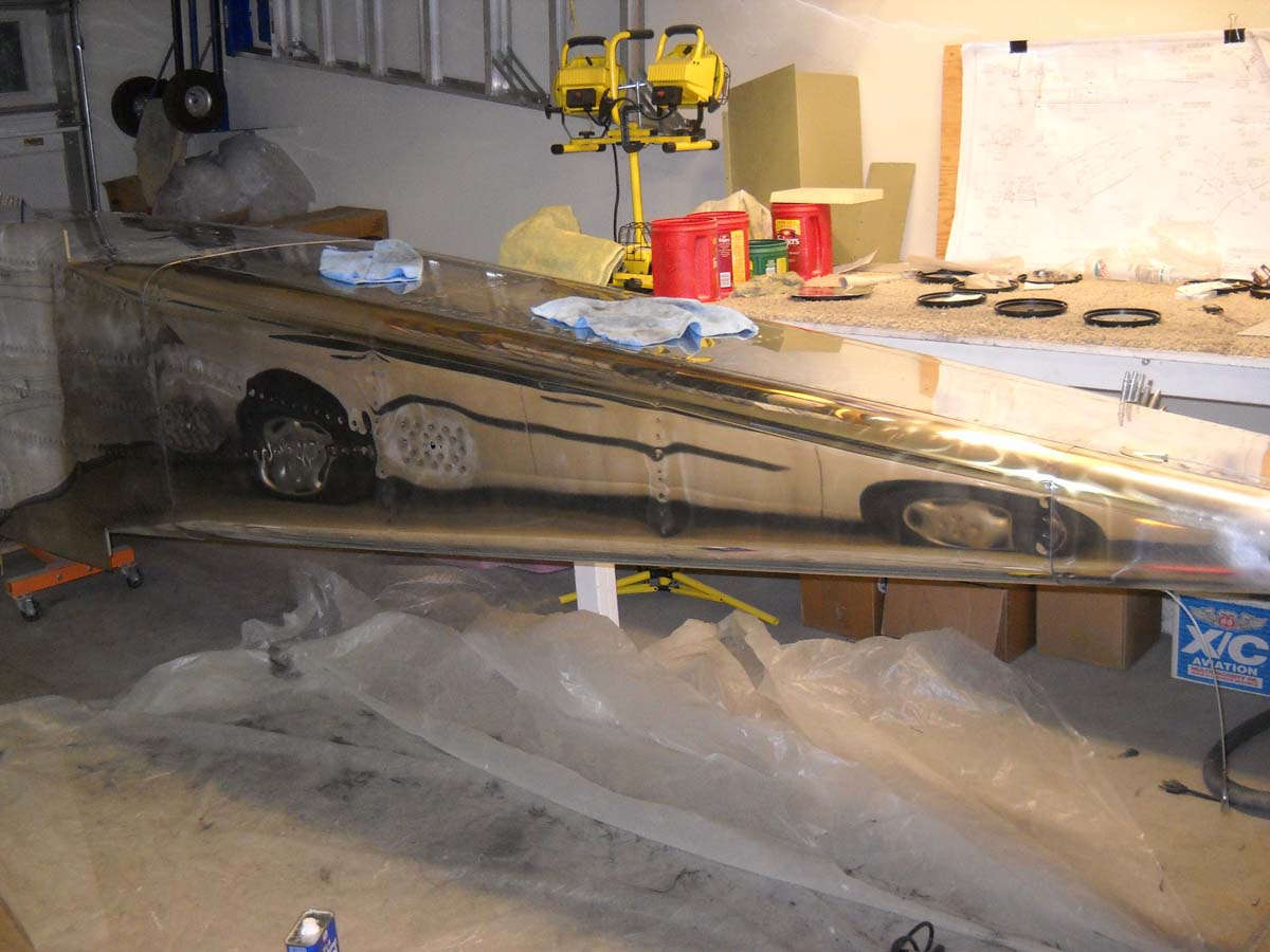
So, on to the aforementioned polishing. Actually, the first step is compounding. I decided to start on the fuselage belly to perfect my technique, then finish the finish on the entire fuselage. This will allow me to keep working of the fuselage with landing gear installation while I also continue polishing the wings.
So, I read all I could on the VAF website, and the Nuvite website, and the PerfectPolish website, about compounding and polishing with Nuvite, the various grades and the various techniques, My first order had both the G6 and the F7 grades in 1/4 pound amounts to try it out.
So, at this point I have done the compounding on the fuselage belly, which was pretty scratched up from assembly "encounters." I found for this work the G6 grade is better than the F7 for the compounding. It takes anywhere from two to seven passes with the G6 grade to remove all but the deepest scratches. Here we are getting started.
So, my plan is to compound with the G6 grade, polish with the F7 grade, and repolish with the S grade, with some C grade thrown in there as needed depending on the skin condition. I admit on the front end that I am not going to be a perfectionist on this skin polish thing. This will be a flying airplane so I expect flying things to happen to it. The Army Air Corps operated natural metal finish airplanes through the 1930s and they looked pretty good, even without Nuvite. For me, polished yes, perfect...well, no.
Still, after the first work up with the G6 compounding on the belly, it looks pretty good to me. The swirls, if you can see them in the photo, should come out in the polishing step with F7. You might notice how I artistically arranged the swirls to resemble a 2003 Ford Focus. That was not easy.
Many hours of work lie ahead with this part of the project, but that's part of it, eh?
August 12, 2013
Over the past two weeks the time I devoted to the RV-8 was spent polishing the fuselage. I was able to complete the work on the fuselage belly and the entire aft fuselage. I learned a whole bunch about polishing which will prove useful in the next weeks.
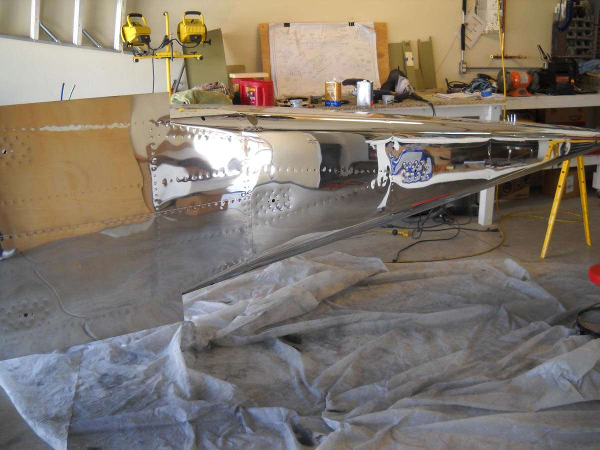
Here is the underside of the fuselage after it was completed. I must say my belly has never looked this good before and won't likely look this good again. Take it however you want.
So, the fuselage side skins were pretty scratched. I had removed the protective blue vinyl much earlier in the construction process because I had decided there was no chance I would decide to polish it after all. Well, never say never, or so I have heard, and I changed my mind.
So, I am not an expert by any means but this is what I did. I compounded with the polishing machine with Nuvite Grade G6. I made two or three passes over the entire area I was working on, usually about three feet square. I quickly came to figure out what was the right amount of G6 to use based on how obscured the metal became after the first run with the polisher. After two complete passes, the skin basically looked okay except for all the scratches and pit marks and, it turned out, flecks of dried epoxy from the canopy work. I originally made continual repetitive passes over these areas with more G6 using the same technique as the first two passes, that being vertical up and down in the same direction. After a while I modified my pattern and used the polisher back and forth, up and down, over the scratch or blemish, working it from all directions with a good shot of the G6. This seemed to work better and quicker. The deep scratches did not come out, but I guess that is too much to expect. You can't really add clad back into the scratches, merely minimize the edges a bit.
The end result after the G6 and a good cleaning was polished surface with lots of swirls from the compounding. It looked pretty good at this point because after the cleaning the compounding material is gone and the scratches are only visible with light shining across the surface.
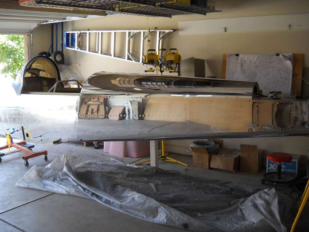
Then, I switched to the cyclo machine with the felt polishing pads. I went over the entire area, i.e., the whole aft fuselage side, with the cyclo machine and Nuvite Grade F7. This removed most of the swirls and brought the polish up quite a bit. Went from good to better. I thoroughly cleaned the surface again after this step with mineral spirits and microfiber towels.
Then, I repeated the cyclo over the entire area with Nuvite Grade S, This removed virtually all of the swirls left from the compounding and visibly added depth to the polished metal. Looked awfully good at this point. After being happy with the S Grade polish, I did not clean with mineral spirits here but final polished with high quality microfiber towels with cornstarch, and worked carefully to make sure all the rivets and seams were polish free.
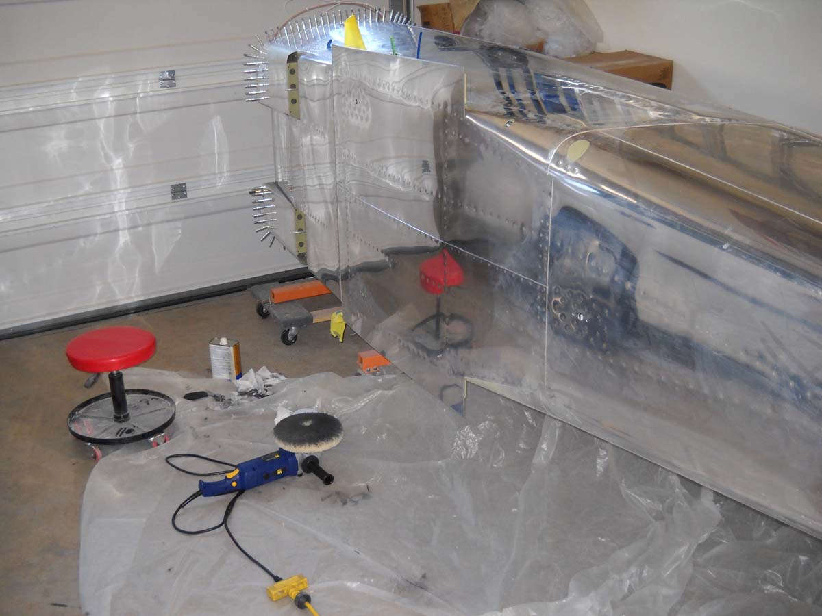
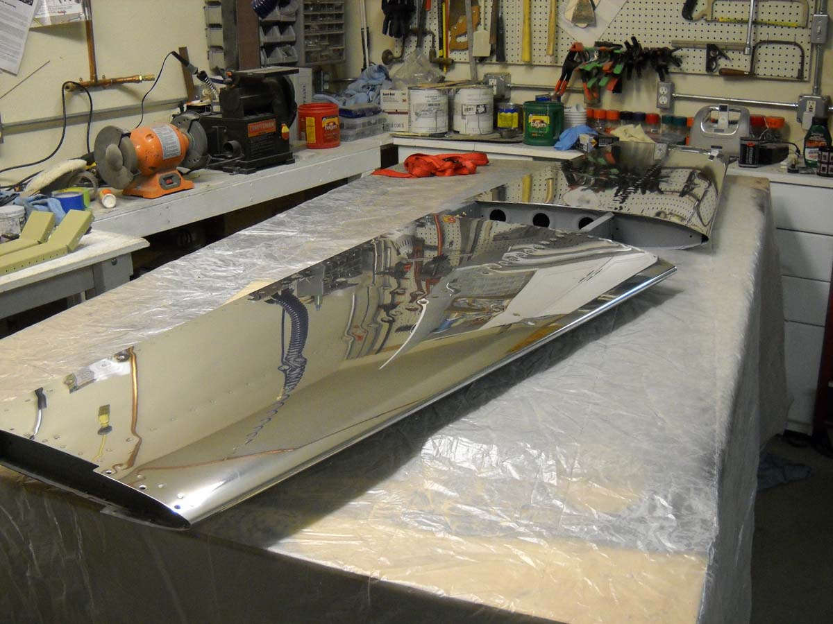
As can be seen, the result is pretty dramatic.
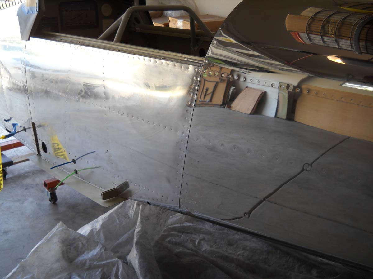
This view compares the forward and aft sections of the fuselage.
Like I wrote last time, I am not going to be a perfectionist with this polished skin. I probably spent twenty hours to this point on the fuselage, and the parts I have worked on look just fine to me. There remain scratches that will not come out, at least with me in control of this process. But, this thing is going to look damn fine when it is finished, thank you very much.
All that aside, with my minimal progress on the financial front and my engine fund, I would imagine the whole airplane will be polished at least once more before it flies, still several years down the road.
I took better care of the wings and empennage, so I expect that polishing process to go a bit easier. I may start with F7 on those parts instead of the G6. We shall see.
September 3, 2013
I finished the job of polishing the fuselage, at least the first go around. It will receive more attention later but I will now move on to the next thing.
The next thing, then, is to prepare the part of the fuselage that will receive some paint for primer. That would be the fiberglass around the windscreen, which will get silver paint, and the area forward of the windscreen that will receive a black anti-glare panel of sorts, though it might end up being glossy paint. Still, it will be prepped. At the same time, I will also prepare the canopy for priming and then silver paint. I am using Ranthane paint from Randolph via Aircraft Spruce. What they had suited my needs, or at least the needs I think I have.
Somewhat slow going with other things going on. I hope to apply the two-part epoxy primer this weekend, then wait one week for it to cure before applying the silver Ranthane over the primer.
Also coming up will be the effort to start polishing other airframe parts, possibly the wings next. Along with that will be some finishing of wing things like the pitot tube attachment and the pitot heat wiring.
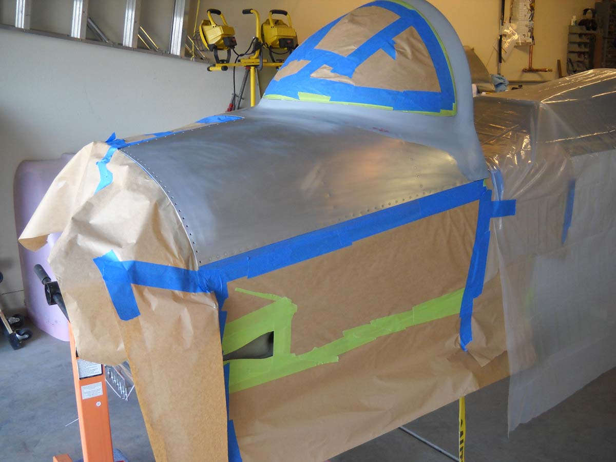
September 25, 2013
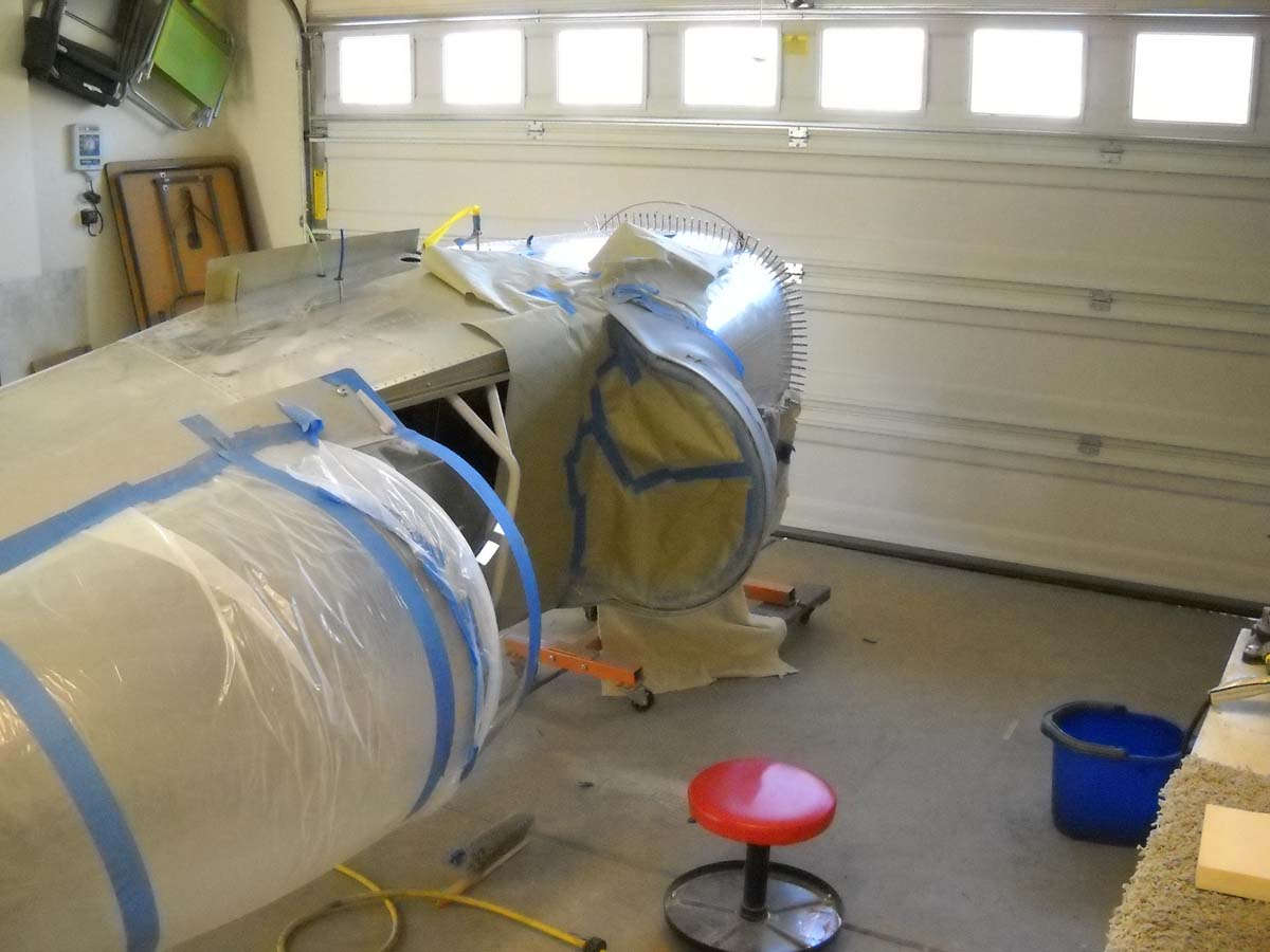
Doing prep work for painting three areas silver on the fuselage: the area around the windscreen, the fiberglass on the canopy, and the fuselage NACA vent. First step was to sand and prepare the surface, then mask off the areas for the application of primer and paint. Then, two weeks ago, I shot the Ranthane two-part epoxy primer on those areas. Three thin coats using my old Harbor Freight HVLP paint gun. Worked fine.
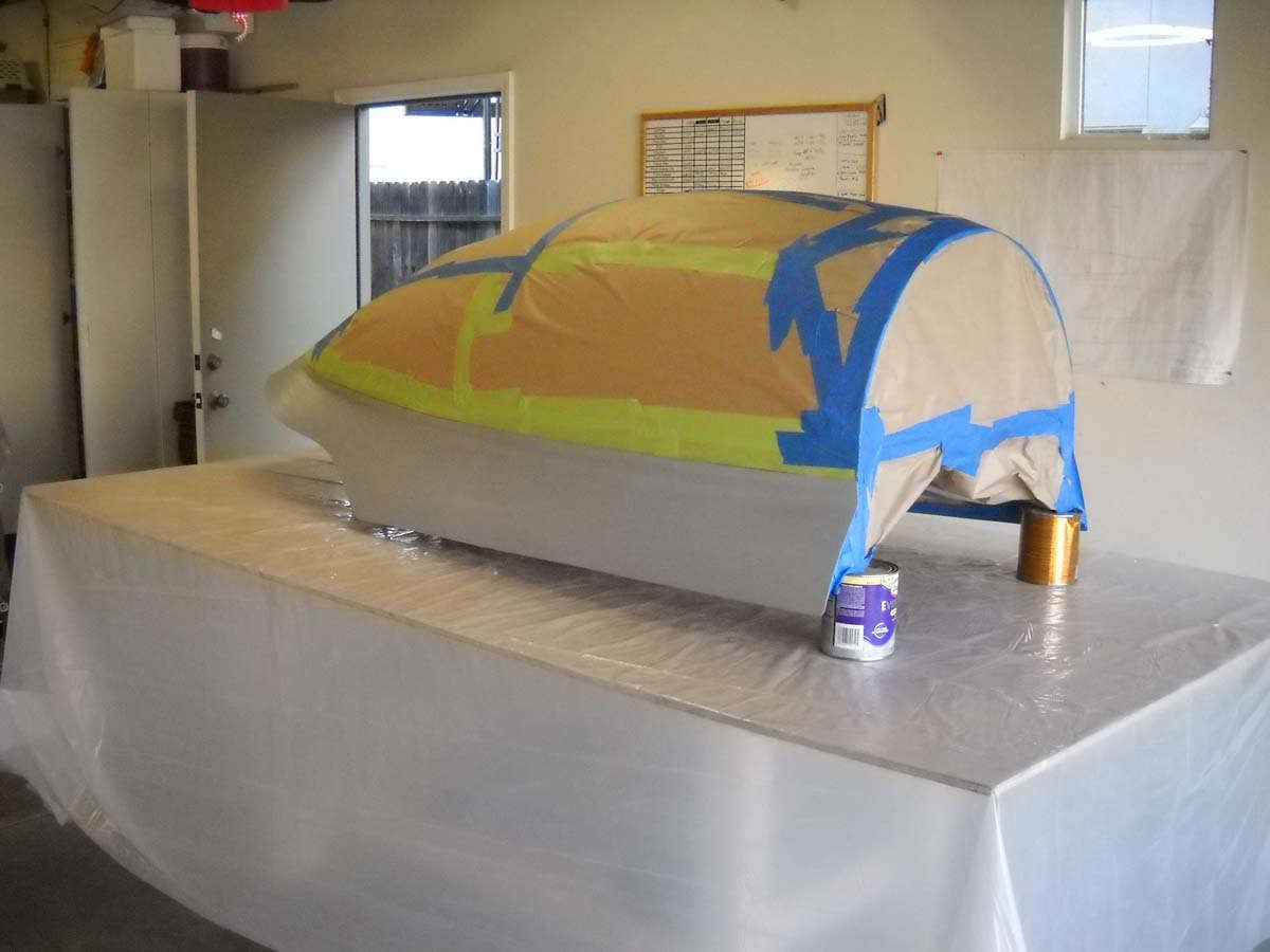
Here is the canopy after priming.
My intent was to let it cure for a week, as per the instructions, and then shoot the actual silver color. Unfortunately, when I went to mix up the two part product, I lacked the third component: the Ranthane thinner I needed to mix in before I shot the paint.
For the Ranthane, you mix two parts paint with one part catalyst (and let chemically work for twenty minutes), then three parts catalyzed paint to one part thinner. Not sure how I missed ordering the thinner in August when I went to Aircraft Spruce in Corona to pick up my paint, but I rectified it by ordering two quarts of thinner and, of course, paid the hazmat shipping charge I was trying to avoid the whole time. Nonetheless, the thinner is now on hand and I expect to paint these three parts next weekend. We shall see how this turns out, my first try and shooting polyurethane. I am using a Hobby Air whole face fresh air mask and other protective gear, and a makeshift paint booth.
September 28, 2013
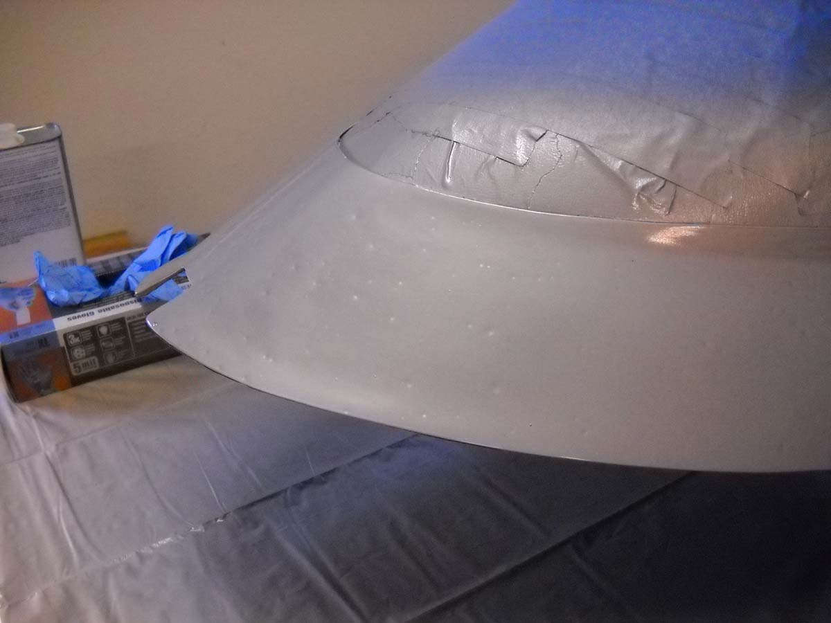
Paint: Fail #1
So, I made my first attempt at shooting Ranthane polyurethane silver paint last night. It started fine but got progressively worse and by the time I was done, I had a massive number of fish eyes all about the painted surface. When it started going south, it only got worse.
I am pretty sure my problem is water in the air line. I have a filter but it is, I think, substandard and not doing the job. My immediate future involves, 1) doing a bunch of sanding; 2) replacing my water filter with a new unit; and, 3) adding an inline water filter just before the paint gun.
As I think back a bit, I remember that I had noted to myself to change the water filter and ensure dry air prior to painting. Not like I have not had time to address and rectify this issue, especially with an extra week of delay thrown in by the lack of thinner. Note to self: remember notes to self.
First off, I will find out how long I need to wait after shooting three coats of Ranthane before I can begin sanding. Nothing like watching paint dry, with monuments to my oversight staring back like, well, fish eyes.
October 28, 2013
Spent a somewhat unproductive month trying to get this initial attempt at painting to work for me. I'd like to say I was successful and I have been to a certain extent, but not entirely.
So, here is the windscreen with the silver surround on the fiberglass fairing. Black will eventually be added to the area forward of the windscreen but that is a bit off in the future after the cowling is fitted.
And the canopy itself. More work to do here but it is a start.
My trip up the learning curve provides a few suggestions that furture painters can take or leave (consider the source):
But, besides rubbing out the paint a bit, I am moving on to finish a few small items on the fuselage, like add an aft baggage switch and light, and move the forward baggage light a few inches, and then do a thorough interior cleaning. Then, I will reattach the canopy sliding rail and, of more interest, bolt the landing gear legs onto the fuselage. All in the next week or two or, in my RV-8 construction time zone, about four months.
November 12, 2013
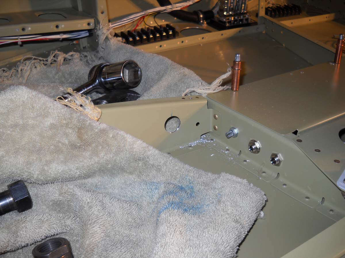
Did work on the landing gear and made some good progress. Basically, the landing gear was mounted and bolted into place, then the fuselage was rolled and set on its new landing gear. I added the tailwheel and removed the engine stand from the firewall. This was substantial visible progress, even though it remains three steps forward and two back sometimes.
Here is my son Lucas doing some preparation work prior to mounting the left gear leg. Having a second set of hands definitely makes things much easier when installing these gear bolts.
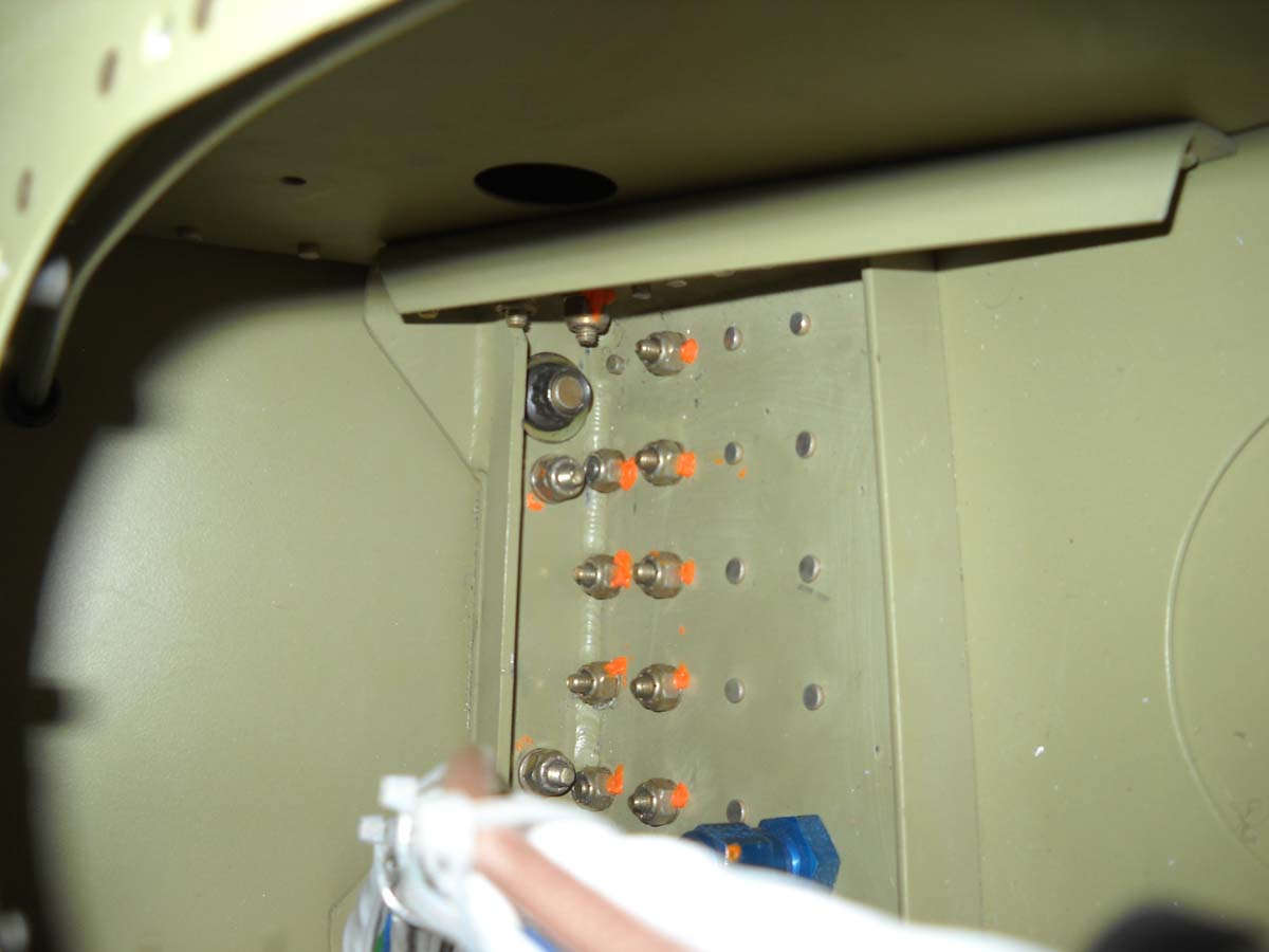
There are five bolts that hold each gear leg in place, two outboard and three inboard. The two outboard ones are reached through the gear towers and can be hard to get to.
Through research and seeing what others have done, I became a bit concerned about perceived weakness of the standard nuts supplied in the Van's kit to hold the outboard gear leg mount. The bolts are close tolerance NAS6206-27 bolts with hardened washers, and the standard nuts are supposed to be NAS679A6, though the ones that came with my kit appeared to actually be MS21042-6s. In any event, the provided bolts are, for lack of a better term, low profile nuts about 2/3 of the vertical height of a normal nut and therefore has fewer threads that engage the bolts. This has concerned some builders and there appear to be some documented failures and/or loosened nuts of these critical fasteners. Much stress is transmitted to these two bolts/nuts, particularly with forward and aft stresses.
Trying to preclude potential problems, I purchased four NAS1804-6 nuts that are considerably stronger and are full-sized nuts, therefore engaging more of the bolt threads. Here is one of the nuts inside the gear tower after the installation and applying 240 inch pounds of torque.
I confess I may have a problem in that I do not have a thread exposed through the top of the nut. The higher profile nut, it turns out (and not really surprisingly), may need a longer bolt, so I am not necessarily done with this nut/bolt combination. I have a bit more research to do to decide on buying four NAS6206-28 bolts that would give me another 1/16" in length. More to follow here.
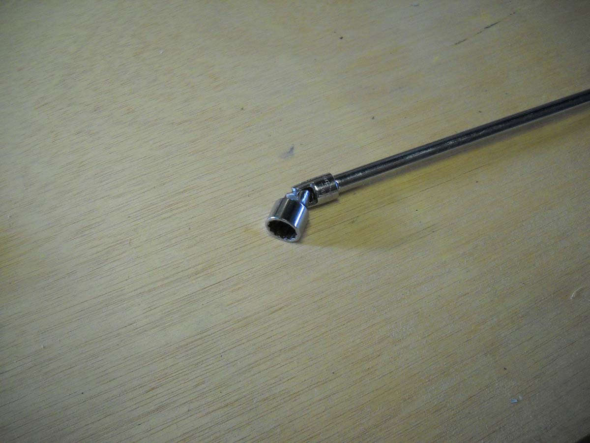
All that aside, I will mention that these two Snap-On tools, the extension and particularly the swivel socket (7/16" in size) proved to be incredibly helpful in tightening the hard to reach nuts inside the gear tower (thanks to Greg and his tool box). This swivel socket uses a 1/4" drive and is small enough to maneuver into position and will hold the nut through that maneuvering to allow the nut to engage the threads, and then to properly torque the nut. Each of the two nuts are slowly torqued down (the book says alternate tightening the nuts in 5 inch-pound increments to reach the 240 inch-pound value) so being able to switch the socket back and forth between the two nuts is invaluable.
So, I enlisted fellow RV (RV-7, actually) builder John to come over and help me jack up the fuselage using a Harbor Freight engine hoist, and roll it over to put it up on its main landing gear. Worked out quite well. Thanks to John for the extra set of hands.
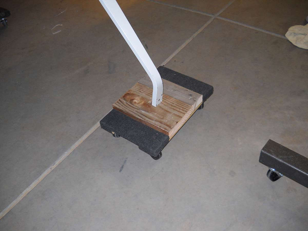
And here is one of my modified Harbor Freight moving carts that will serve as a temporary rolling gear. I later added zip ties to hold the gear mostly in place. What could go wrong? They are nylon.
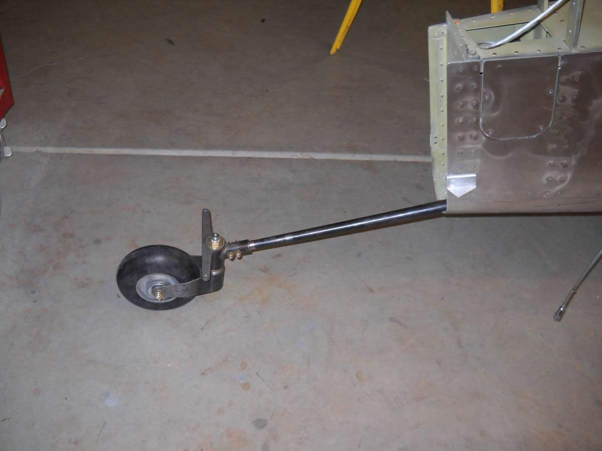
And, here is the tailwheel assembled and attached to the aft fuselage. Should be a permanent installation here. No need to rework or add work here.
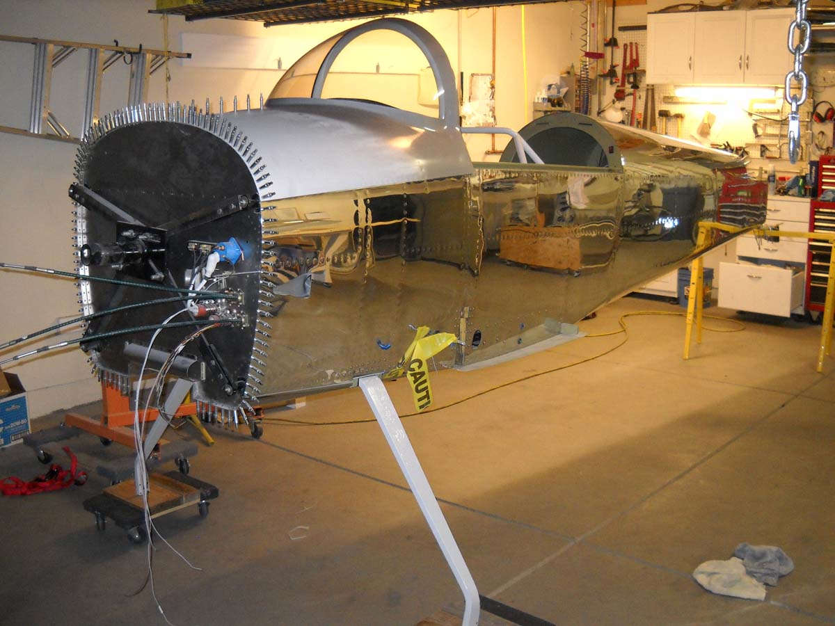
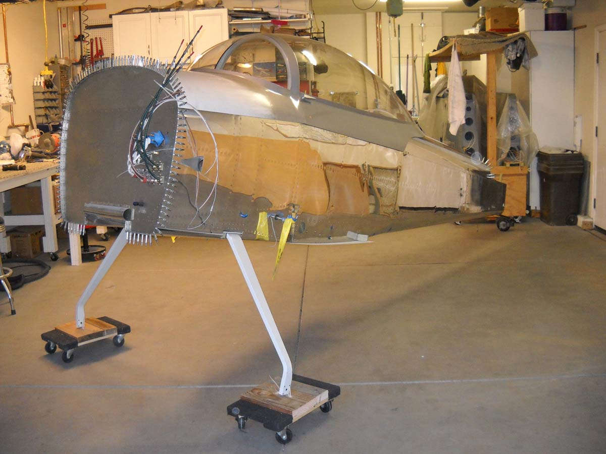
So, here is the end product. The RV-8 fuselage is on its gear pretty much in the attitude it will have henceforth. Looks pretty good to me. I added the canopy for aesthetics and for test purposes.
Well, the test purposes was to sit in the fuselage for the first time, really, with the whole thing pretty much configured as it will be when I fly it. Ergonomics, how well do I fit, visibility, engine noises, etc. Fit pretty good. I can't wait to fly this thing, but I have to wait. Engine and avionics. And money.
November 30, 2013
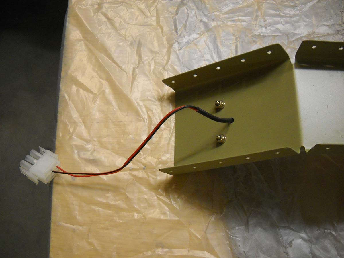
Not too much in the past few weeks. However, I've done a bit of final wiring in the fuselage. I had previously wired two convenience lights, one in the forward baggage compartment and one in the aft. They are wired to the hot battery bus so the battery master switch does not need to be on for them to work. I had made provisions for a similar cockpit light and completed the wiring on this yesterday. Basically a simple LED light, a Radio Shack push button switch, and a Molex connector. I added the connector because of how the light is mounted. I can disconnect if need be.
And, today, I polished the horizontal stabilizer. Took maybe two hours to do the job.
Next, I will polish the vertical stabilizer and the elevators. Then, I will assemble the tail components on the fuselage to allow me to do several things: connect the rudder and elevators and do a rough rig of the controls; make sure I have adequate clearance on the bottom rudder fairing with the tail wheel so I can prep that part for mounting and paint; fit the empennage fiberglass fairing; complete the wiring for the elevator trim and the connections for the AeroLed tail nav/strobe light. Those things will all take a while to complete so the tail will be assembled for several weeks while I accomplish that work.
December 31, 2013
A summary as I end my fifth full year of airplane building and start my sixth. I look at the RV-8 kit in my 'hangar' and see and airplane now. As I end this fifth year, I am working to attach the tail feathers and make most of the adjustment and wiring connections that will be finalized a few years down the road, but will be mostly completed now. 2013 has mostly been spent wiring and that entailed a bunch of planning to settle avionic decisions. Also, small tasks were completed, a process that will continue through the next year or two as the airplane is being readied to fly. The elephant in the room, as it were, is the big void forward of the firewall, one that may still be a year or two away from filling, maybe more. I am still set on installing a new or gently used IO-360-M1B fuel injected engine, so we shall see. That and a constant speed propeller. If my bank account were fuller, this airplane would be flying within a year, so that in itself is pretty cool. Not a bad way to start 2014 either.