|
Attaching the Empennage Fiberglass Tips |
November 2, 2009
So, flew a week on business, then spent last weekend on B-17 stuff that wasn't RV-8 stuff. Okay, then, and then a busy following week trying to catch up on "stuff," whatever that is. So, for the RV-8 project, that left a bit of time, maybe five or six hours, that I was able to dedicate on Saturday. Then busy on Sunday and here I am in Medford, Oregon, flying again and not working on my RV-8. But, alas, earning money for mortgages and food and a bit for the RV-8, so it is connected.
Back to the task at hand, I had spent some good quality online time here and there researching the wonderful world of fiberglass. Something I've never done before, so it an educational opportunity. On Saturday, I got all the empennage tips out and starting putting thought to action.
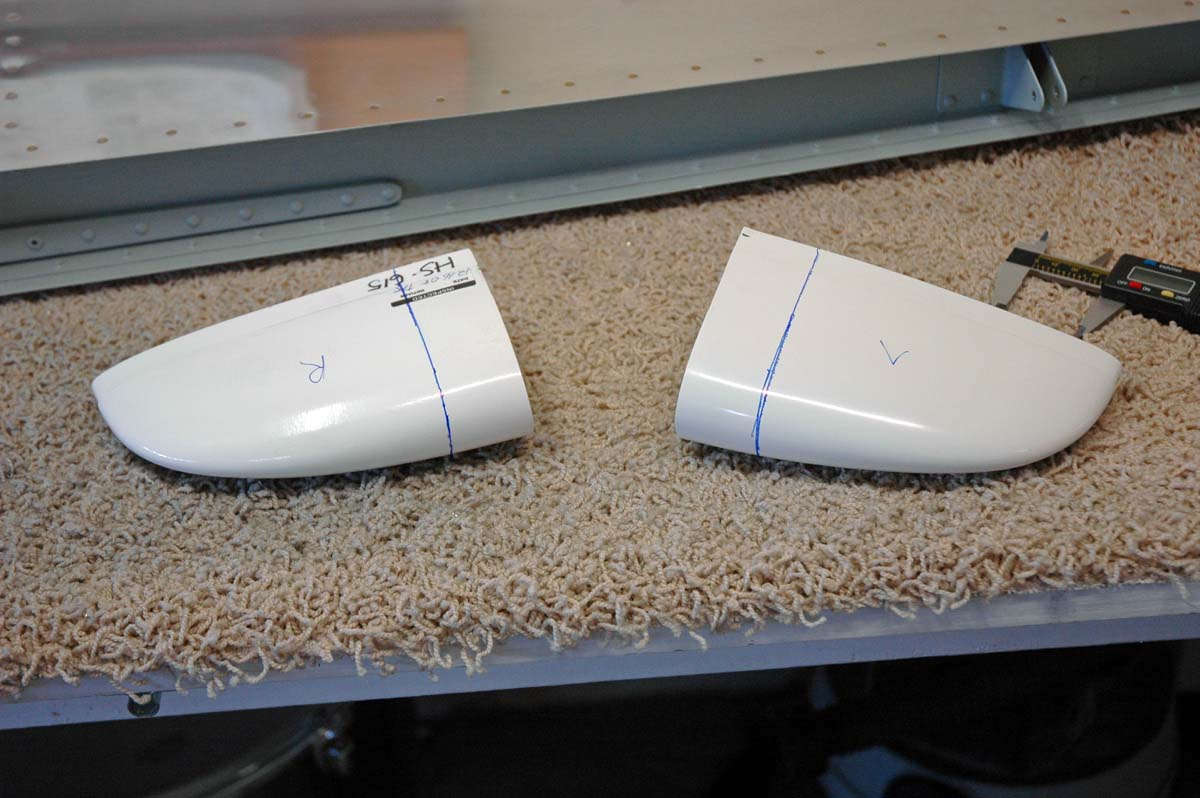
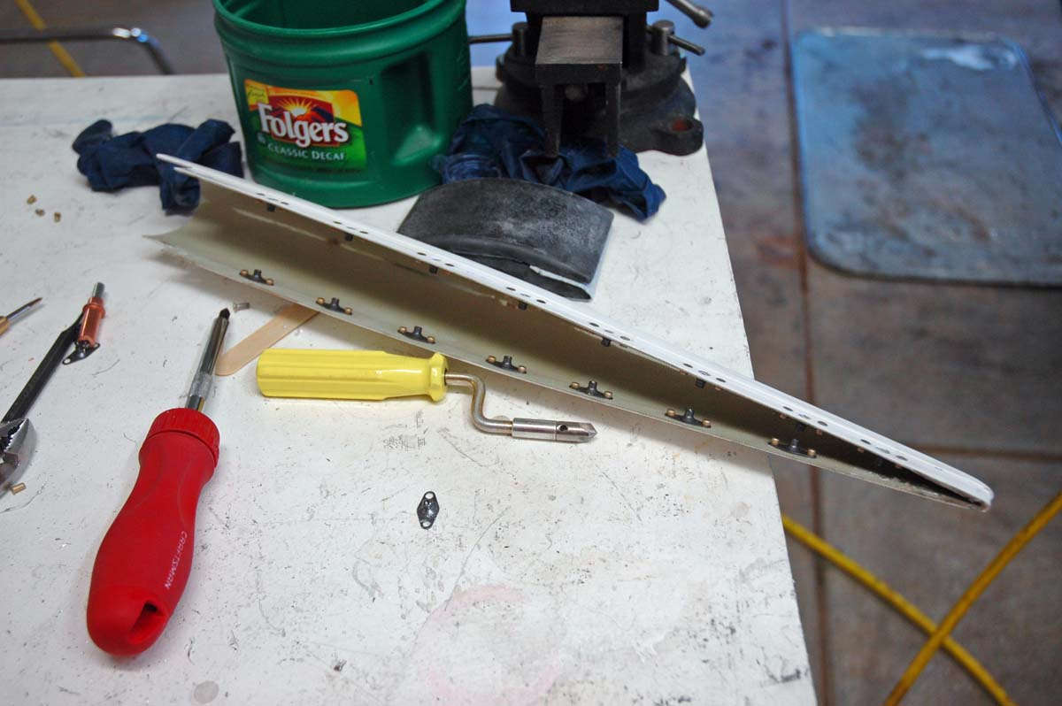
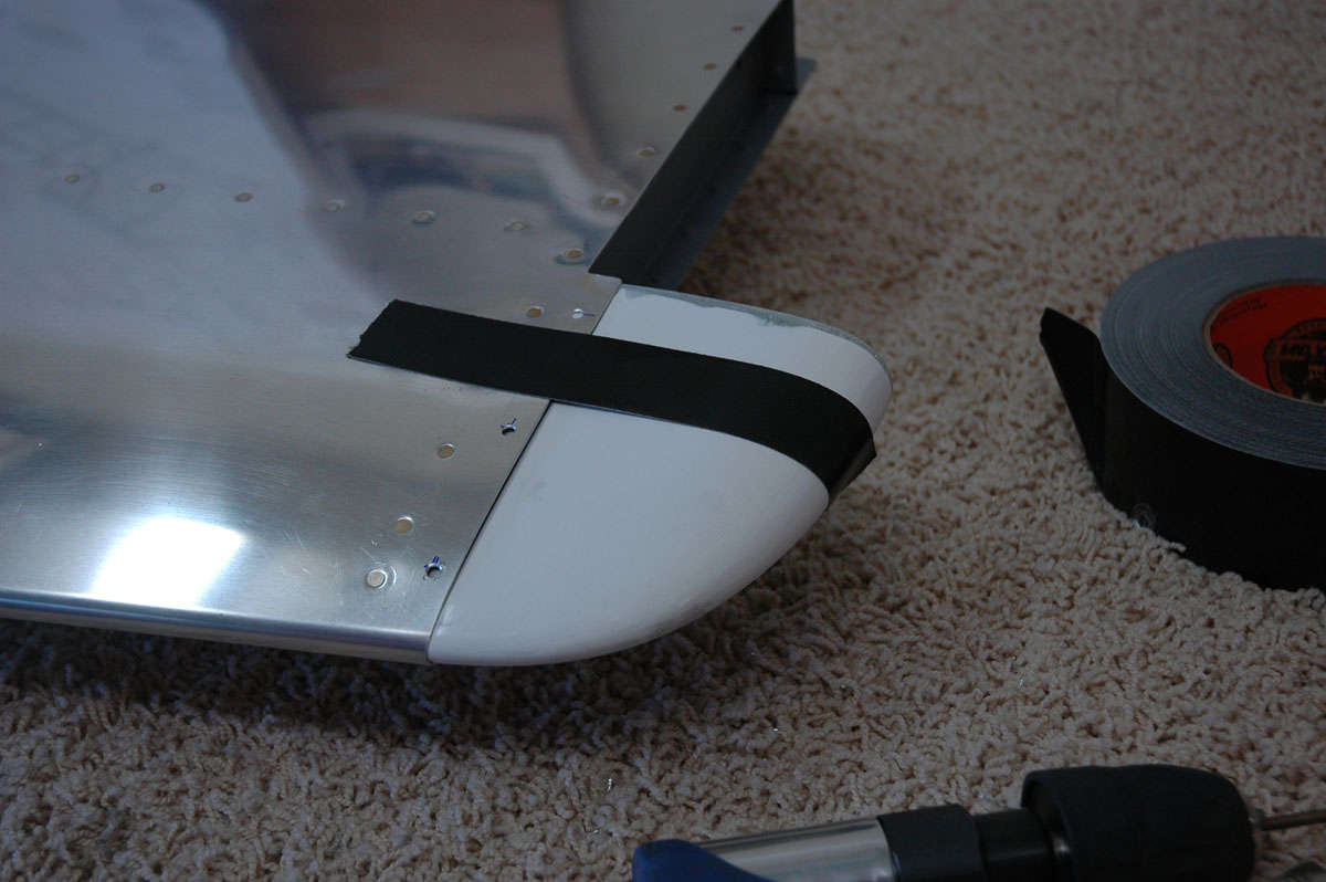
Here are the horizontal tips. There are several decisions to be made here. The Vans Plans call for the builder to simply ("simply" being a relative thing) blind rivet the tips and then do some filling and smoothing the seams that make the transition to the metal parts. Others suggest using nutplates and screws so that the fiberglass is not permanently attached...thus easier to repair or remove if needed. What complicates both approaches is that the horizontal stabilizer and elevator tips have ends that are open that really should be closed in, both for aesthetic and aerodynamic reasons. So, whichever way it is done, you are probably going to get to deal with epoxy and fiberglass cloth and hardeners and other such things.
And the fiberglass world can be a confusing one, indeed, what with so many different types of epoxies and resins and peel plys and glazing compounds and fiberglass cloth and fiberglass tape and Elmer's glue. Well, I just made up that last one but you probably can do fiberglass with Elmer's glue, just not on my airplane.
So, I pondered and thought and initially decided to go the nutplate and screw route, primarily because I want to be able to get the elevator tips off if I need to adjust counterweights, and to provide access to the rudder bottom (navigation light) and vertical stabilizer tip (VOR antenna?). So I went ahead and order a bunch of hardware...nutplates and screws and other stuff from Vans.
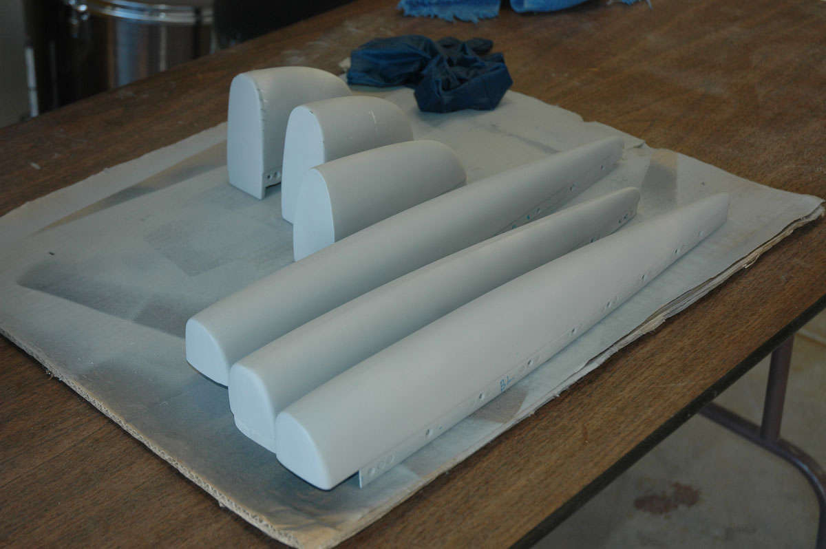
Last Saturday I got all the fiberglass parts out and started fitting them.
So, I measured and marked and pondered a bit more, this being the elevator tips that have to be cut down a bit to fit around the counterweight.
But, you can only do so much 'sticking your toe in the water' before it becomes time to dive in. My Dremel tool, carefully used, makes the needed cuts.
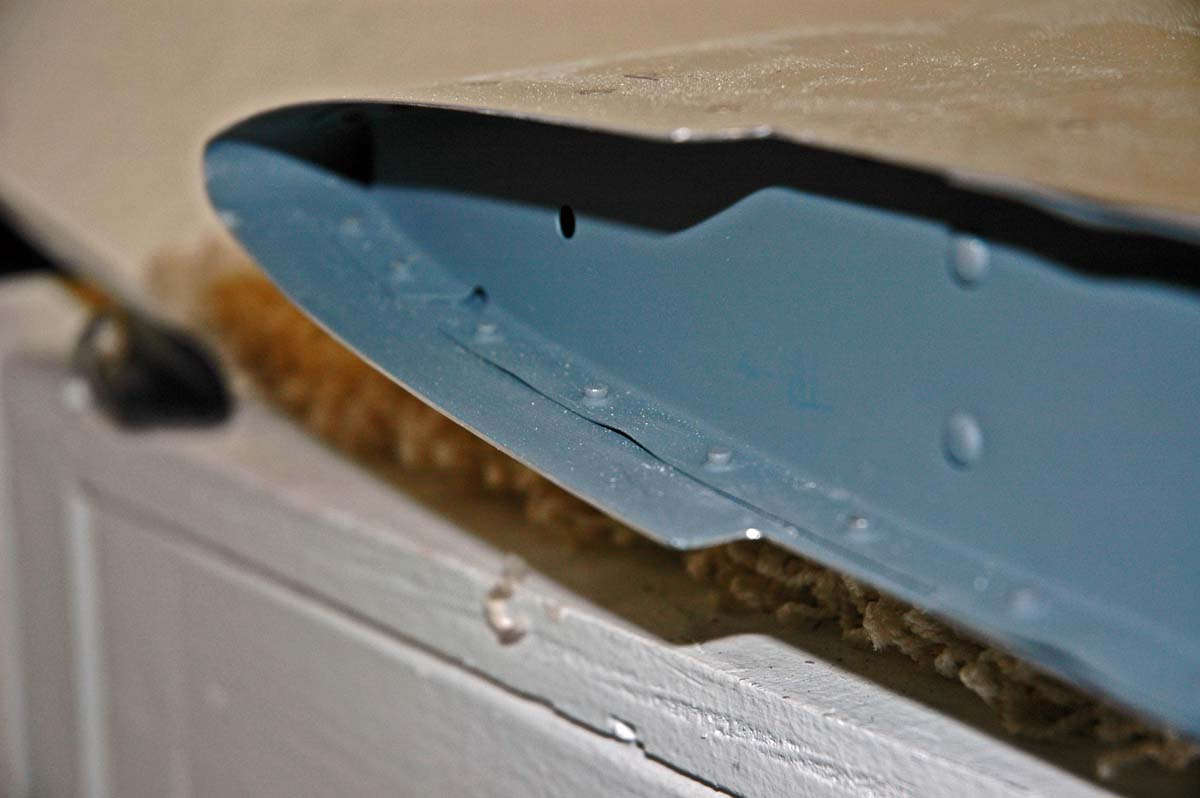
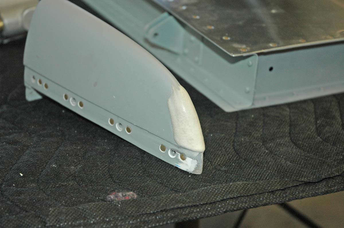
Here are the cutouts on the rudder bottom tip; the cutouts allow the fiberglass part to fit around the elevator horns.
As for the elevator tips, the fiberglass tip fits around the counterweight, and the forward end of the counterweight is the part that needs to be closed in with fiberglass.
Trouble is, if you are going to attach the elevator tips with screws, the fiberglass has to fit around the counterweight without being attached to the counterweight. The only thing I could figure out is that the counterweight has to be filed down to provide the room for the fiberglass build up. This is okay for the right elevator as it is nose heavy; not so good for the left elevator as it is a bit tail heavy with the trim servo. More on that later.
Here is the rudder bottom fit into place. As I worked with the parts I modified my original thinking: at this point I intend to permanently attach the horizontal tip and rudder upper tip (possibly) and use the nutplate/screw arrangement for the rudder bottom, elevator tip, and rudder upper tip. Until I think about it more, I guess. There will be some careful fiberglass work to make some of these parts fit better. More to come next time.
Speaking of fitting, I took the time to fit the rudder according to the Vans Plans (three different tie rod distances for each of the three hinge points). Worked out pretty well, except I'm not pleased with the gap between the rudder and vertical stabilizer at the top. Seems a bit tight to me and is not quite even. I think if I readjust the top and bottom tie rod lengths I will bring it closer to the ideal.
So, that's about it for a Saturday session. Except I ordered some fiberglass supplies from Aircraft Spruce, but will purchase the epoxy and hardener from a local supplier to avoid paying for "hazardous" material shipping. There is a local plastic shop that I will visit soon.
November 10, 2009
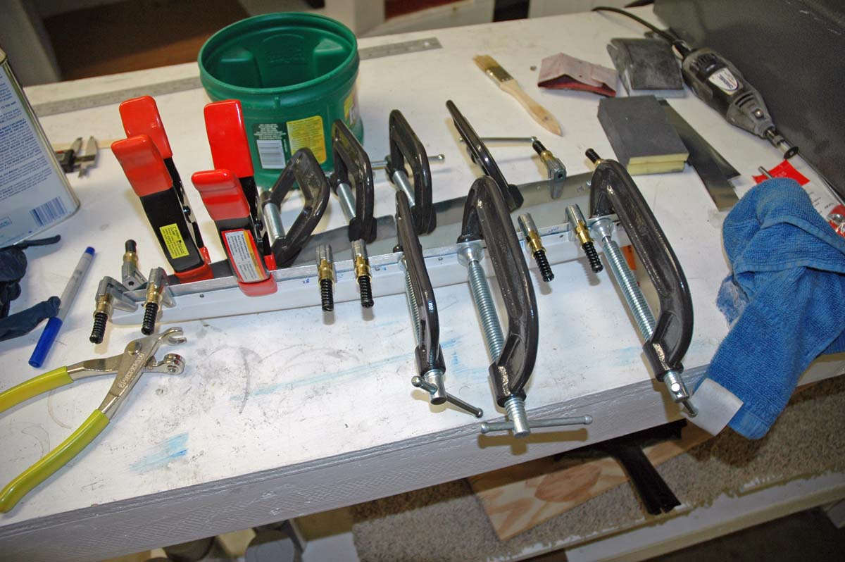
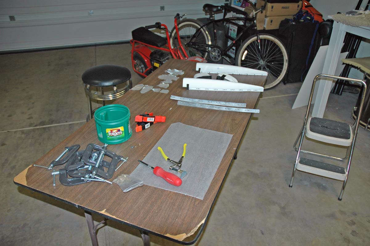
So, I am learning about fiberglass, and not necessarily in a good way. Before I get too far here, I did go to my little plastic store, actually Tap Plastics. Got a bunch of stuff, including epoxy and fast hardener, plastic cups and mixing sticks, and spreaders, and other stuff. My order from Aircraft Spruce arrived with more fiberglass materials. My order arrived from Vans with nutplates and other hardware. All this stuff piled up on my workbench staring back at me.
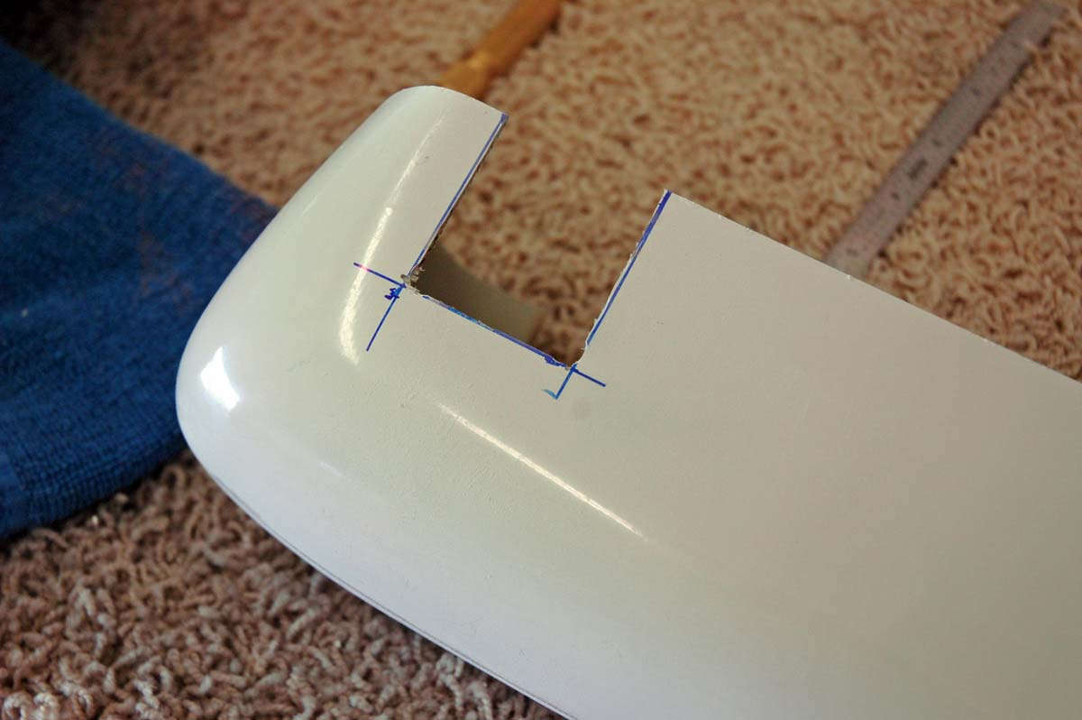
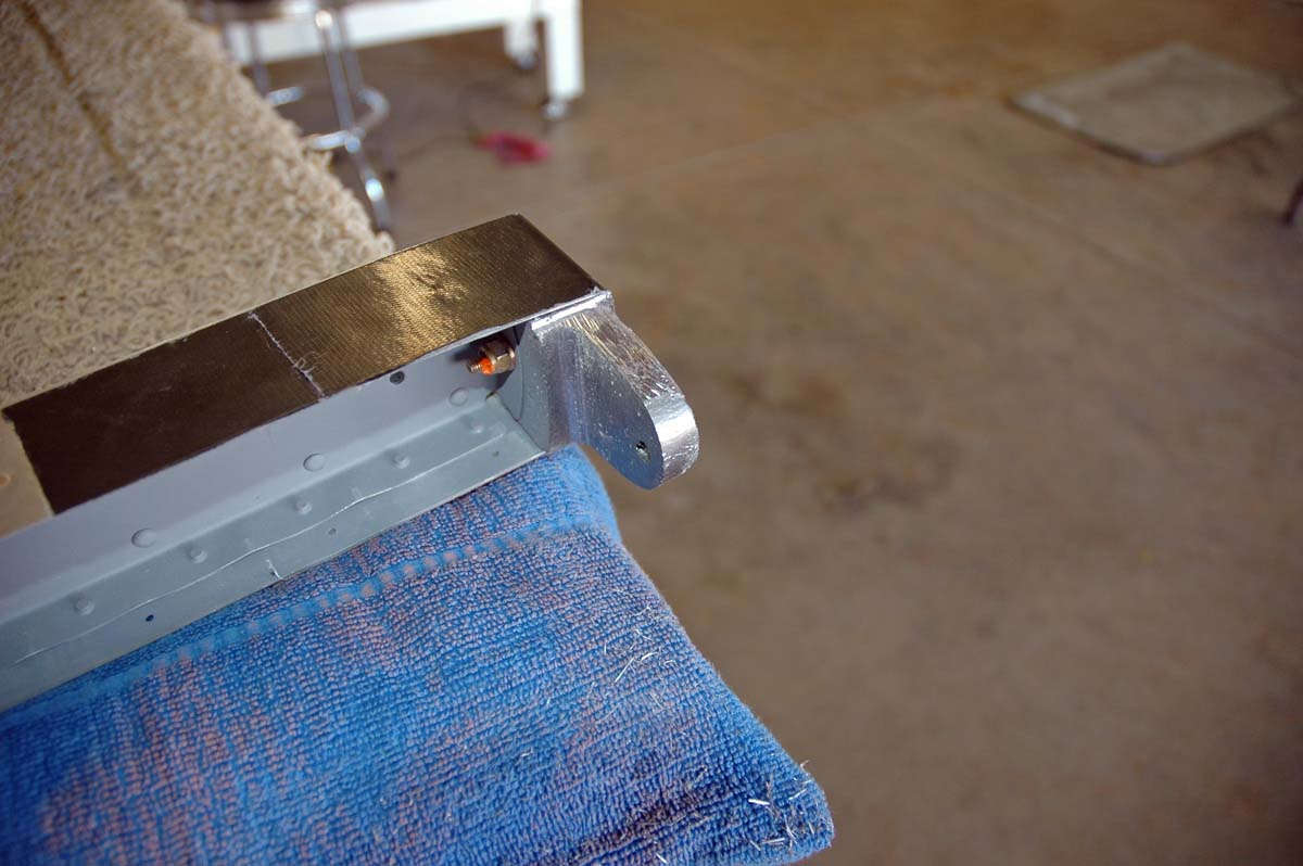
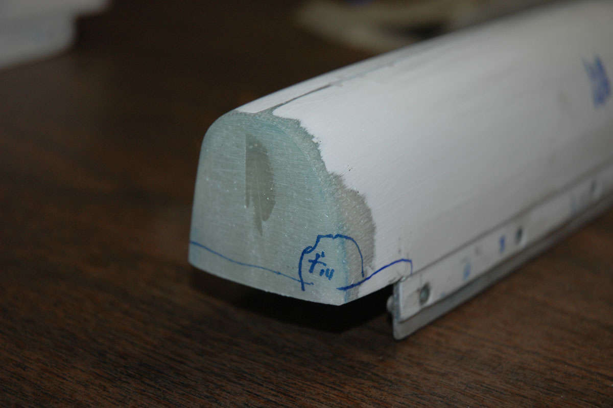
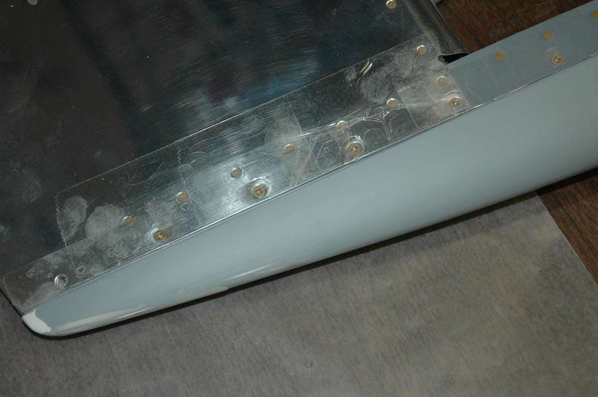
So, I had already done some test fittings of the tips, and all fit pretty well except the elevator tips. It seems the end rib flange interferes with the way the tip fits. Some web sites note that the plans tell you to trim the end rib back to allow the tip to fit, but I could not find that instruction.
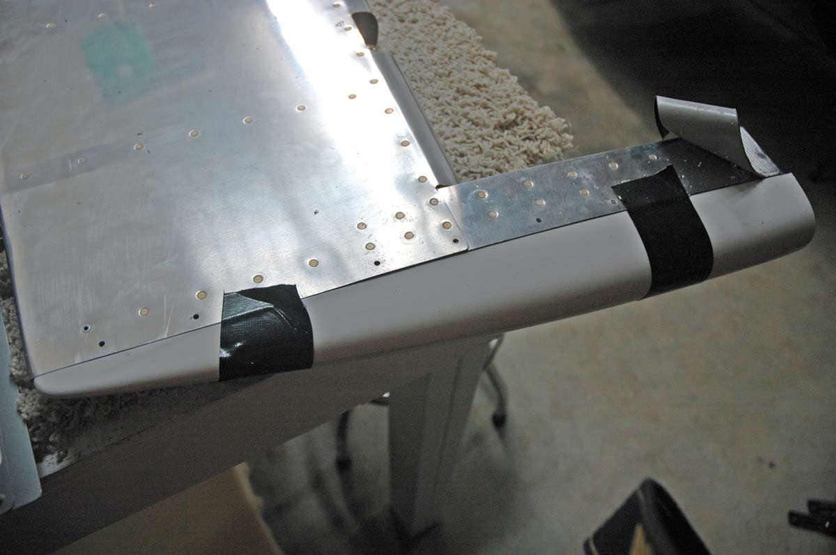
There is a planview (Detail H-H on Drawing 5) that shows a 1/2 inch overlap between the skin and the tip, but that doesn't really tell you much. This photo shows the problem: initially, I thought the flange was interfering with the fiberglass tip fitting; as it turned out, I think it was only the line of rivets. Hindsight is 20/20, though, as this tale continues.
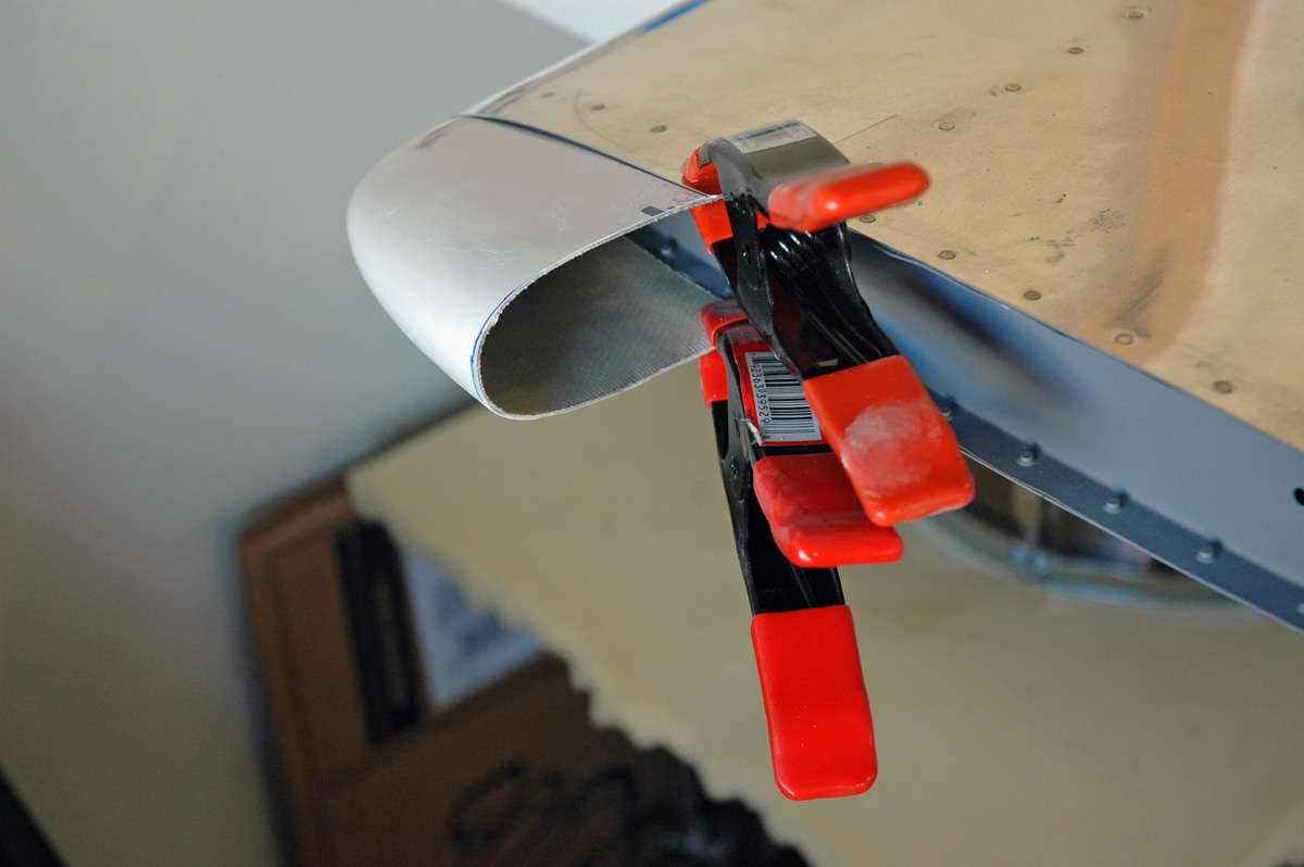
Anyways, it was too late to do any trimming on the tip rib. Reading some other sites, I knew that if I trimmed the fiberglass tip to fit I would have edge distance problems, but that I could use an aluminum backing strip with the nut plates mounted to make it work. So, I dutifully trimmed the fiberglass tip so it would provide clearance between the flange and tip; so far so good but, sure enough, there were issues, like edge-distance issues. Not surprised.
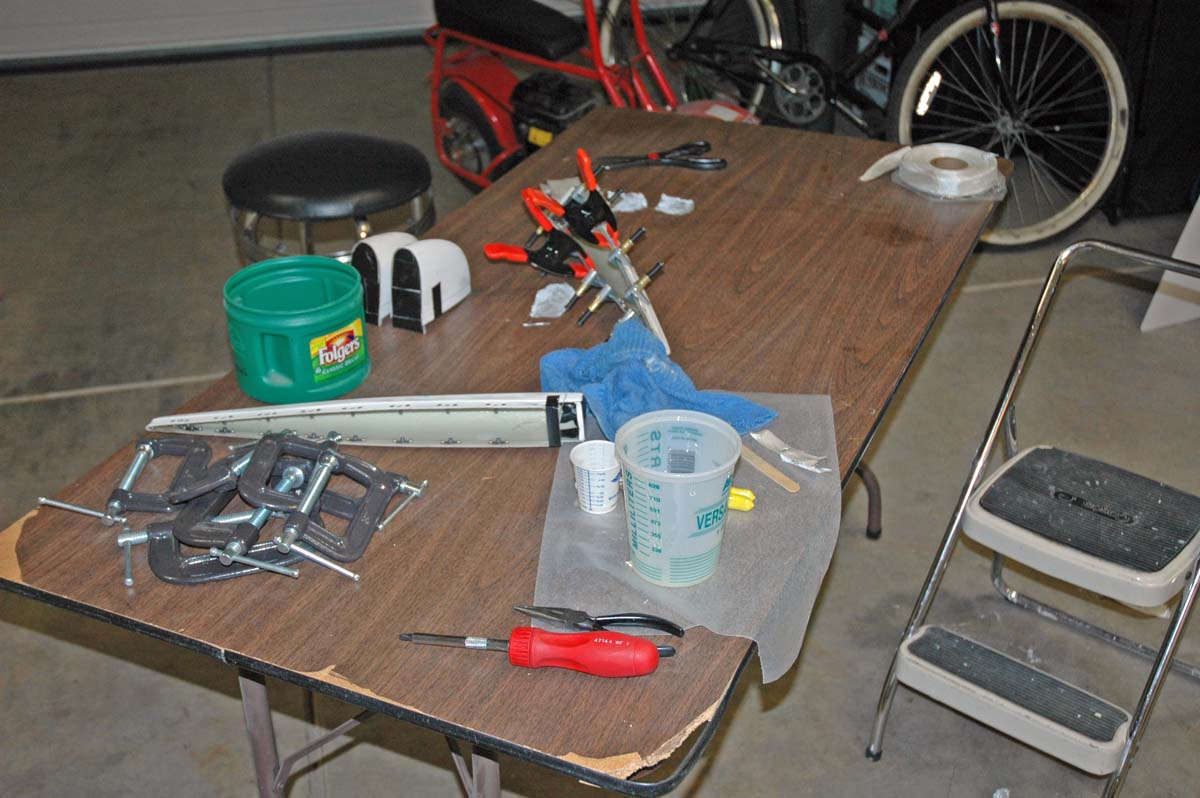
So, I proceeded to manufacture two aluminum "doublers", planning to epoxy them into place and then mount the nutplates through both the fiberglass and aluminum. Epoxy in progress; not a virgin anymore. Maybe I should have stayed one.
Came back the next morning and released all my clamps. Aluminum doublers were very secure. I was happy. Did a test fitting, again, and the doublers now were interfering with the line of rivets. Took some careful measurements, something I should have started with. I realized the flange was not the problem; it was the rivets. I had to trim the doublers back a bit to make it fit. Put it on the sander to make a nice neat trim. I think the heat from the sanding action caused the epoxy to fail, and the doublers started to come loose. I wasn't so happy. Okay, plan B. I had been smart enough not to do both elevator tips at the same time, so this process continued with only one tip. I decided to 1) do new doubler strips with the nutplates attached, measured properly, and then epoxied into position, and 2) do the other tip differently. Okay, made the new doubler strips and drilled for the nutplates.
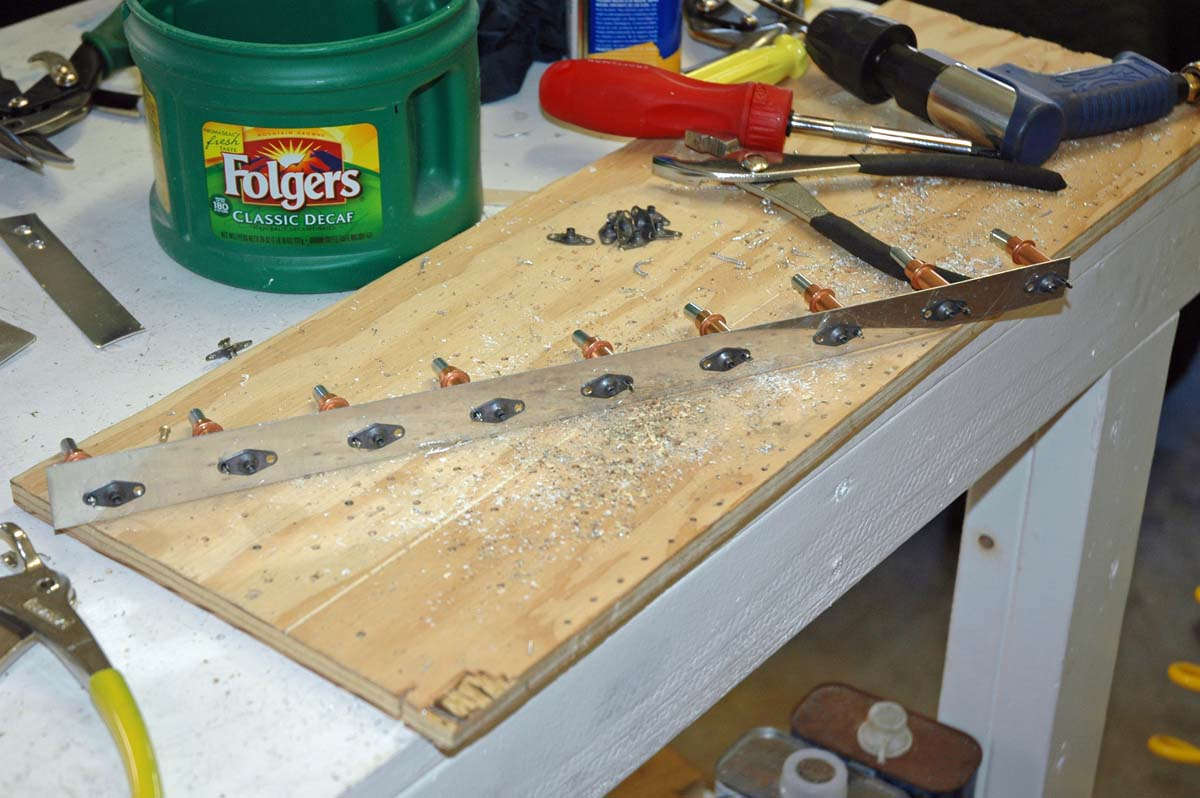
Riveted them into positon, and here is the completed doublers ready to be expoxied.
I then started on the other tip. Decided to trim only enough off to allow the edge of the fiberglass tip to remain clear of the line of rivets. Okay then, use the Dremel and trim the fiberglass.

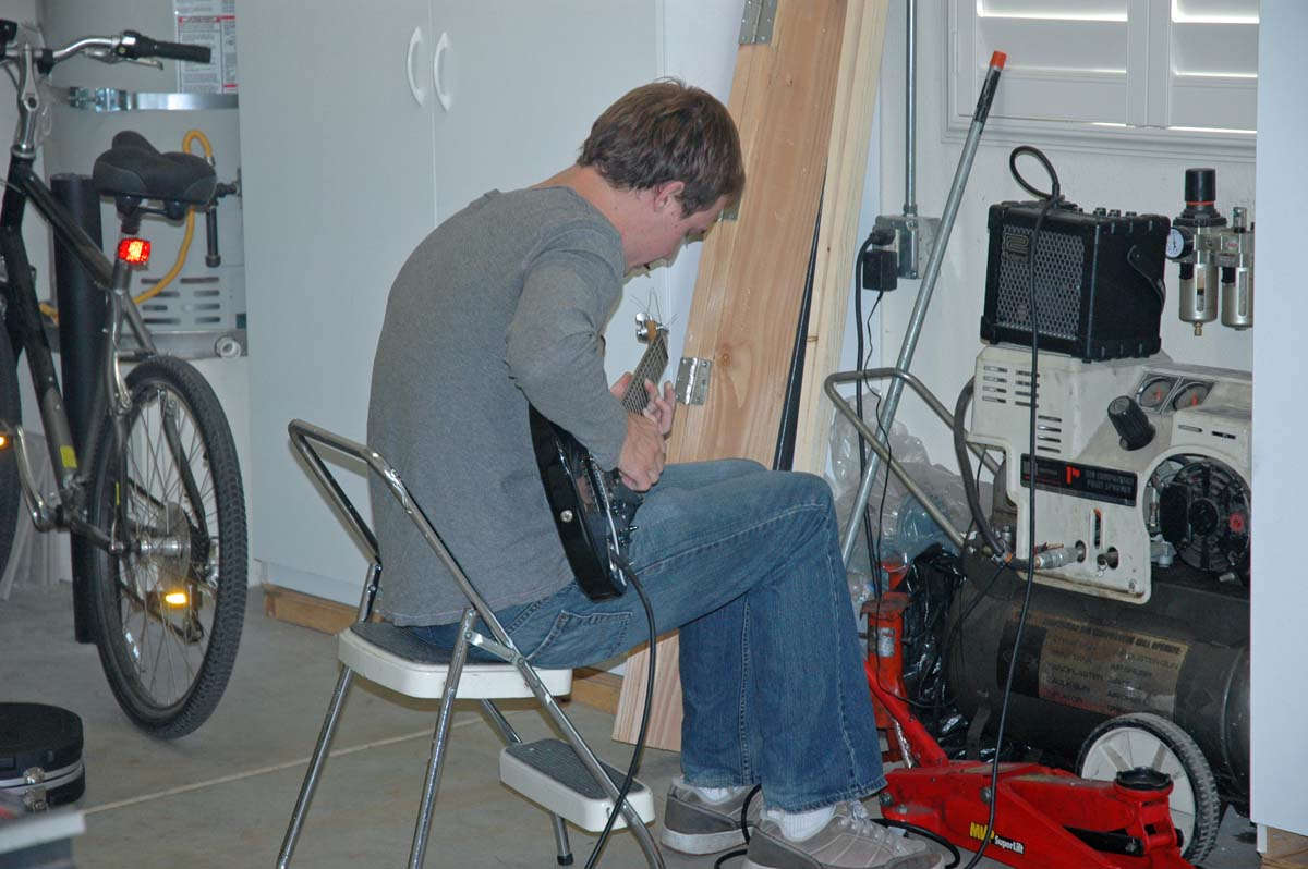
During this process, my son Nathan came out to the garage to keep me company and do some guitar work. I think he is secretly writing a song about building an RV-8 but he is keeping the secret well. Haven't heard the song yet but it might be so secret I will never hear it.
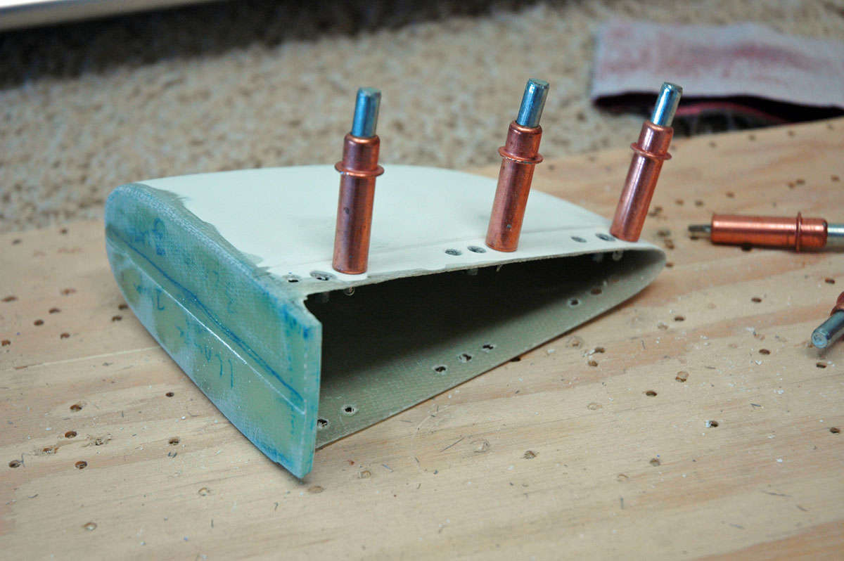
So, drilled and prepped the tip for the nutplates to be riveted into position. Various websites warned about using the hard rivets in this process; others said only to avoid oversqueezing...all you are trying to do is set the nutplate into position. The rivets don't do much more than that as the screw through the skin and fiberglass to the nutplate is doing the work. Sounds good to me; don't oversqueeze the hard rivets.
Riveting went fine, or so I thought. I had to work at the very aft nutplate and ended up epoxying the rivets into place vs. squeezing them due to access issues. By the way, one thing I had to do was to offset the very aft rivets, top and bottom, to avoid the nut plates sitting back to back. I redrilled a new hole a bit forward of the pre-drilled hole on the bottom of the elevator to make this work. Besides clamping, I also used screws through the fiberglass to the nutplates to pull everything up tight while the epoxy set up. Figured the screws would break loose easy enough even if there was residual epoxy that got the screws. Figured wrong.
The next day, I went to unclamp everything and remove the screws. All worked fine except two screws: one snapped in the process of removing it, and the other stripped out the screw head. Bummer. Had to get screw extractors and that didn't work very well with the stripped out screw. Had to remove that nutplate and replace it. Not easy, not pretty, but I think it is okay after all.
That last part came a bit later. First of all, after the tips were done, I figured I would start glassing in the open ends. Got me some foam and used Gorilla tape and set up the two tip ends to add some fiberglass cloth. Planned it all out. Mixed up my first real batch of epoxy and got my cloth, my Bondo cloth, and started to work.
All progressed okay for about 20 seconds, until the fiberglass cloth began to dissolve. Hmmm. That didn't seem right. I messed around with some fiberglass ribbon strips and tried to salvage the situation but decided that wasn't going to work. Meanwhile, my epoxy mixture was undergoing an exothermic reaction, a quaint way of saying it was heating the hell up and starting to melt the plastic container I had used to mix the epoxy. Hmmm. That didn't look right either. Moved that little smoking container out to the side yard to let it do its thing. Lesson learned. Punt for this session.
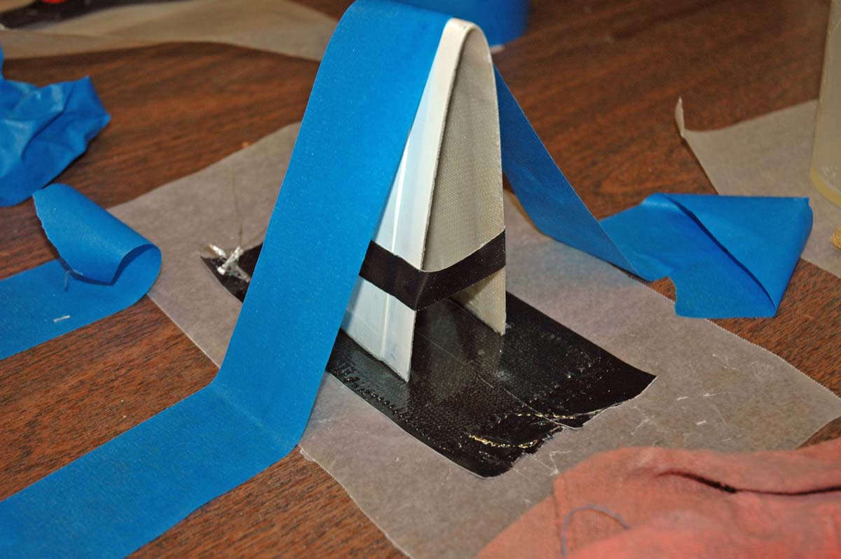
Regrouped two days later. Did the screw extractions as noted above, and decided to use plan C. Got new fiberglass cloth. Adopted another method noted on a website...can't remember which one, but this technique basically lays down epoxied fiberglass cloth and then attaches the tips to them. After it sets up and cures, the inner surfaces of the tips are built up with more cloth and epoxy, and then the thing is trimmed and sanded to fit. Looks easier to me so that is what we are doing here. The blue tape is an effort to press the tips down into the fiberglass; not sure if it doing much but I get an "A" for effort. I did the first two of the set-ups laying the fiberglass on waxed paper. It occurred to me about 2 minutes too late that this might not work to release the epoxy when the time comes. The Gorilla tape works well in not adhering to the expoxy, so the last three were set up on the Gorilla tape.
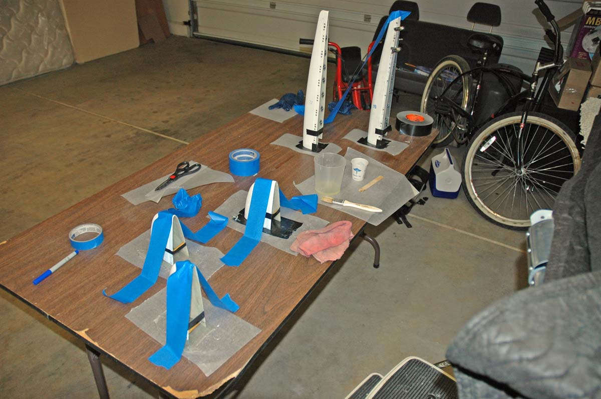
And here is another view. This is the horizontal tip and the fiberglass cloth is sized to accommodate the tab that will fit into the tip rib flange eventually. Stay tuned for more on this process. Over the next few days I will find out if this is going to work. Also in the next few days: attach the rudder tip with nutplates and screws and do the prep work on the fiberglass. Also, I want to finally adjust the rudder to vertical stabilizer distance so that the upper clearance will be better. Plus, a few other odds and ends while I get ready for the wings to arrive.
November 19, 2009
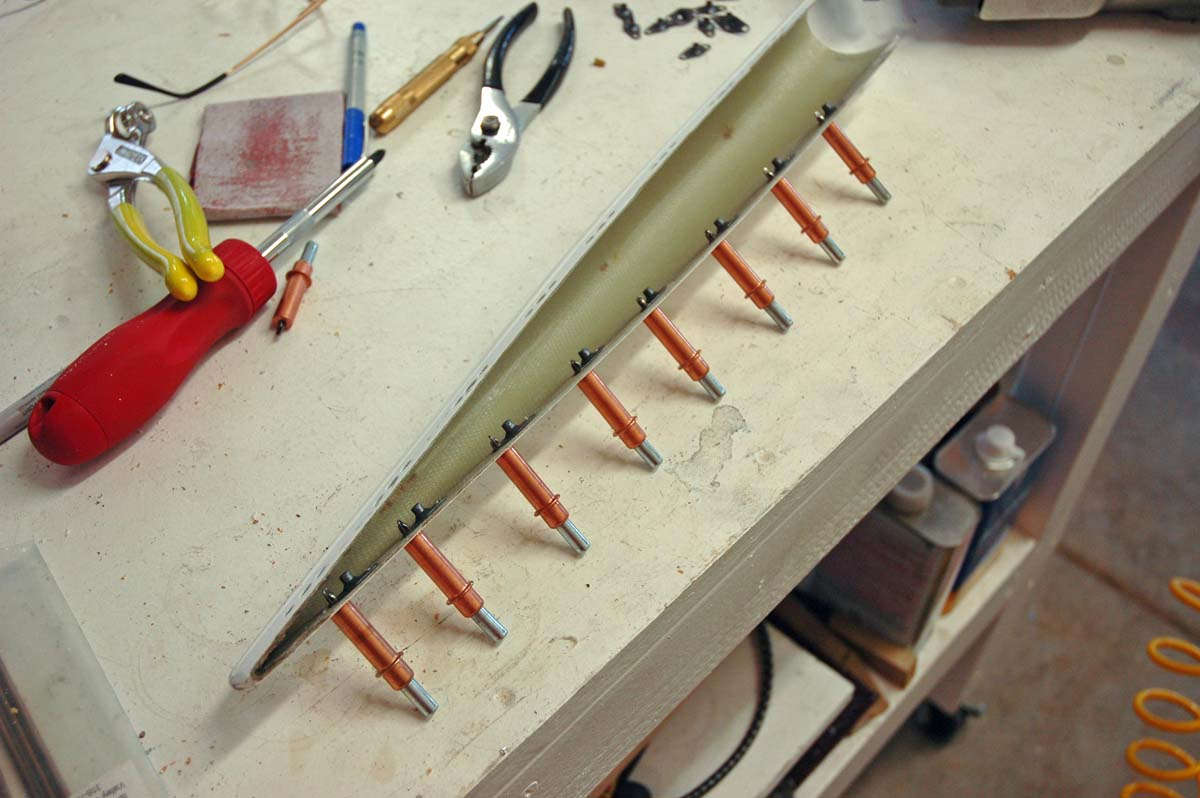
Well, picking up where I left off last week, the process I used worked pretty well to close in the ends. This is the elevator tip with one layer of fiberglass attached...sort of the starting point for the rest of the process.
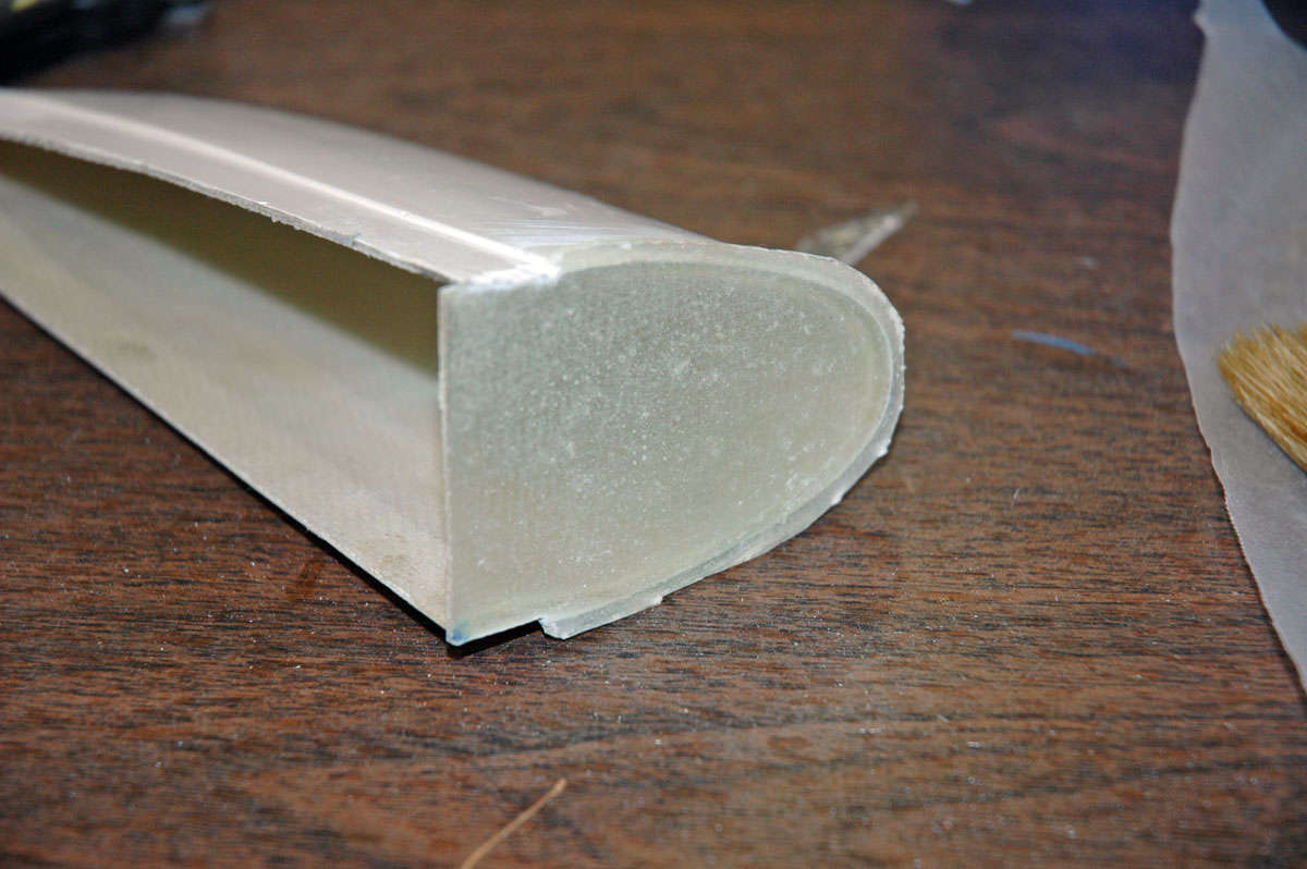
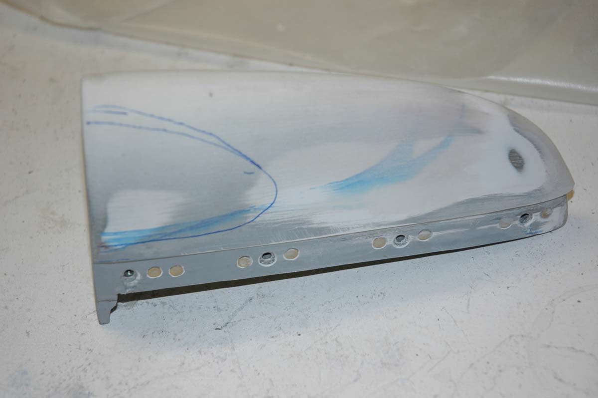
And here is one of the horizontal stabilizer tips with its first layer attached. I've done a rough trim of the fiberglass edge with a closer trim where it fits so I can check the fit.
So, then I mixed up some more epoxy and laid some more layers on the outside edge and then added some microbubbles to some expoxy to build up some of the interior areas. This will, I hope, allow me to trim and sand to the shape I need. All new to me, so this is learn as I go.
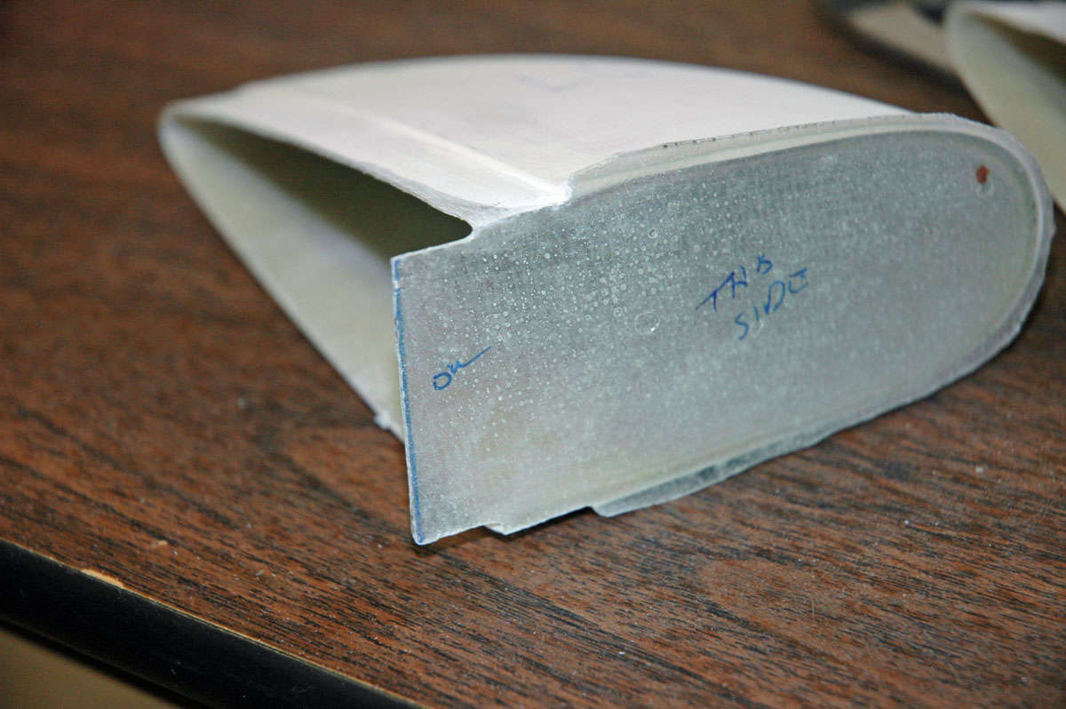
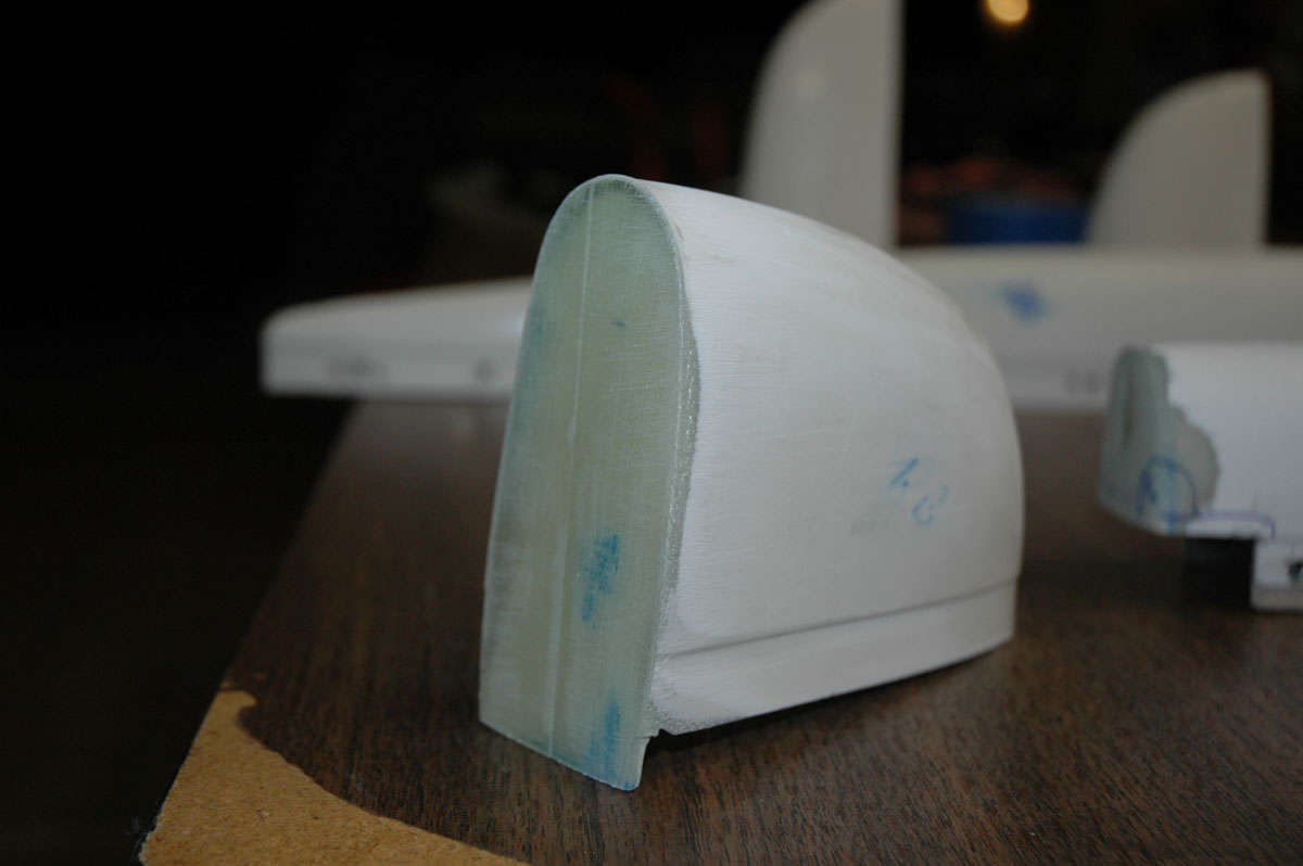
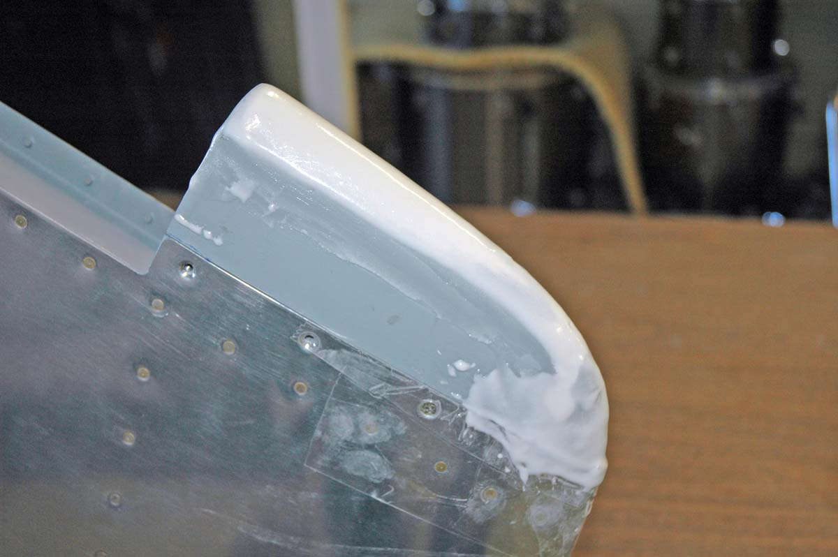
And this is one of the elevator tips. This was the most challenging to do if one is adding nutplates to attach, because the tip must fit over the counterweight and not be attached to the counterweight as it could be if the tip were to be riveted into place. The counterweight needs to be filed down to allow the forward part of the tip to fit, and there can be little internal fiberglass added to the tip where it fits over the counterweight to allow it to fit properly. This makes for thin fiberglass. Here, I have marked up the area where it fits over the counterweight, thinking I could add a bit of filler to close up a small gap. That didn't work out too well, as it turned out, but I tried.
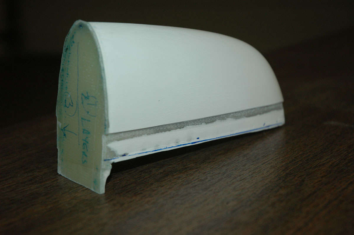
Getting closer with the horizontal stabilizer tips. I had to build up the end piece unevenly to make it fit square in the area where it meets the elevator tip. Not a problem, just laid two more layers on half the end piece to bring the surface up evenly, if that makes any sense. Hard to describe.
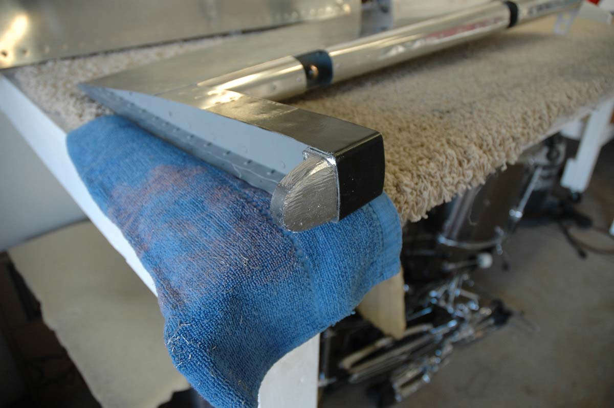
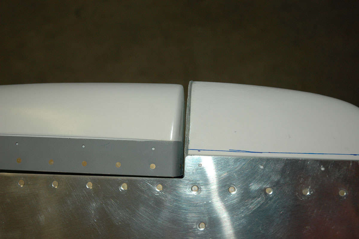
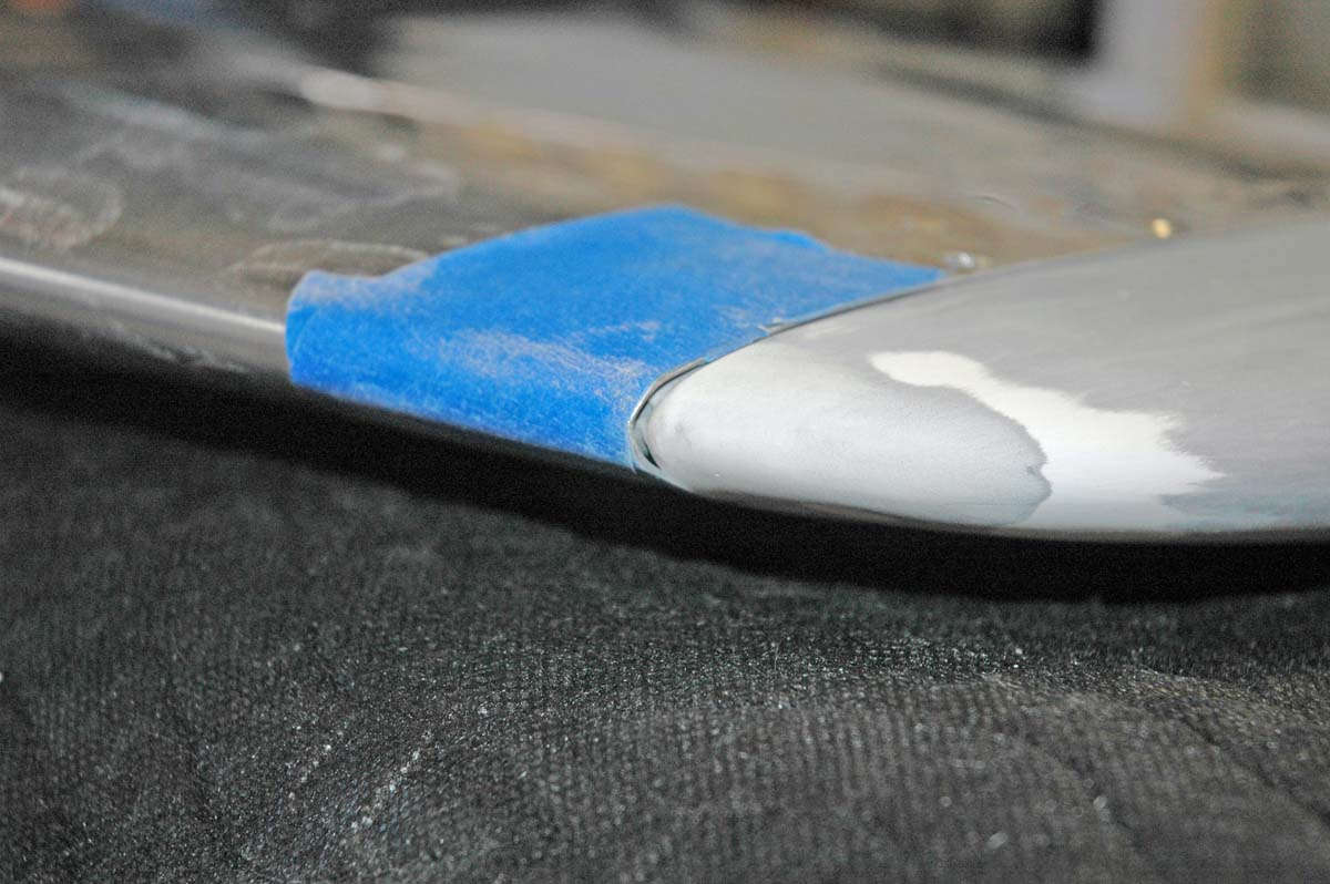
Fitting it all into place resulted in this. The vertical tip fits higher than the rudder tip, not an uncommon event from reading other sites. Some guys build the rudder tip up using microbubbles and sand to fit. I scratched my head a bit and decided to lower the vertical tip a bit instead.
So, I measured the amount I wanted to lower the vertical tip by, and then trimmed with my Dremmel. I then very carefully sanded the raised edge up the side of the tip by the desired amount, and trimmed the tab that fits up against the rib flange by the same amount. Turned out okay, though my sanding thinned out the fiberglass to the point where I needed to lay in some reinforcement on the inside of the tip.
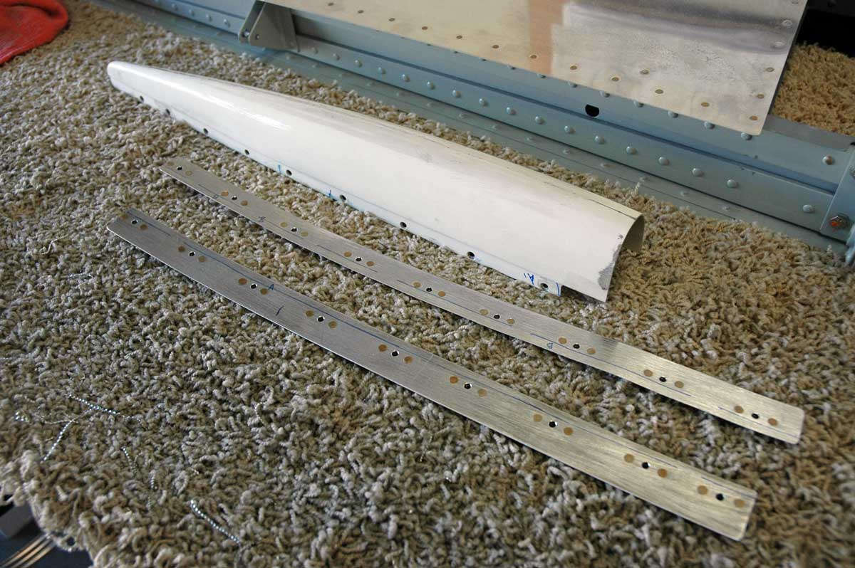
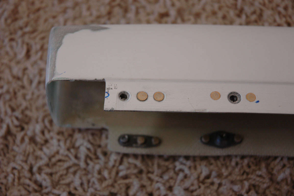
Moving back to the horizontal tips, here I am about to match drill the tips. There were no pre-punched holes here and though the plans call for four rivets on top and bottom here, I decided to match the elevator tip spacing and made just three holes. It will make for easier setting of the nutplates also since there will be a bit more room to work.
So, I set about to drill the holes for the nutplates. Took a bit to get this process down right. I needed to enlarge the nutplates holes for the NAS1097AD4-4 rivets, which I decided was the best way to set them in. Just a bit of countersinking done with the deburring tool will set the rivets in the fiberglass flush.
Okay, making some progress here. Seems like this whole fiberglass thing is taking a long time, which it is. But I am in a but of a lull here anyways, waiting for the wings, and it is good to get over this little skill set hurdle. I've found from the little fiberglass work that I've done is not to be afraid to try something. Most fiberglass errors can be readily corrected.
By the way, I am intentionally not doing the rudder bottom tip. Several sites have noted that for the RV-8, the tail wheel mount interferes with the bottom tip, and it needs to be cut down to fit. Thus, that part will be done later. Need to install a position light on that part also, something else that will come later anyways.
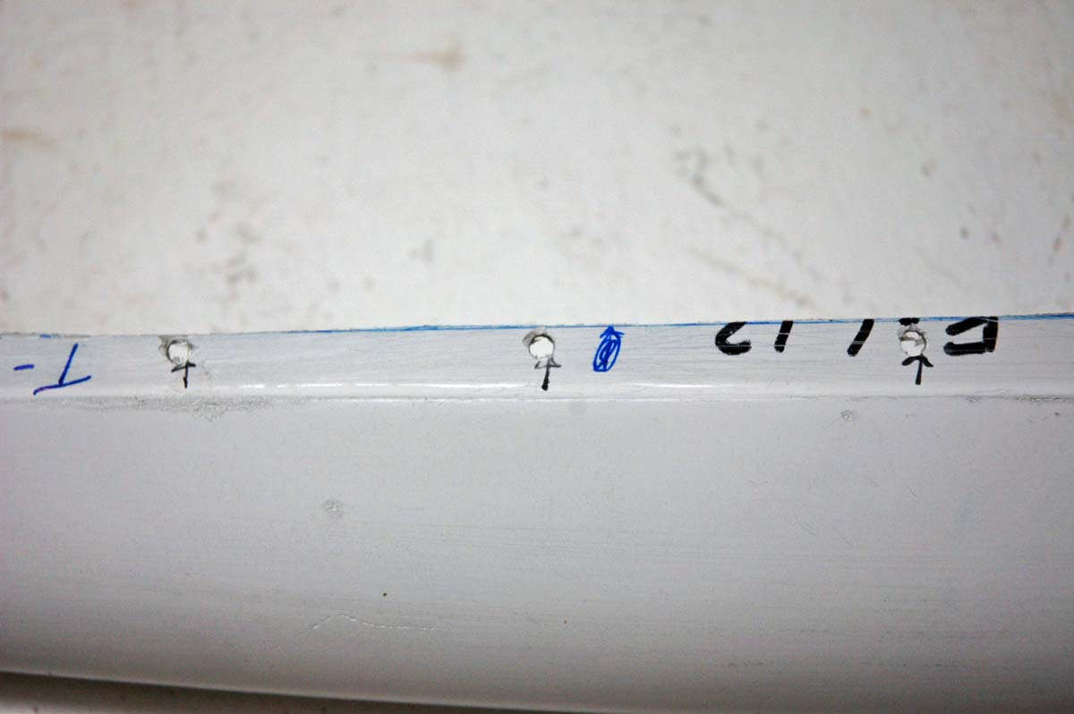
So, here I am setting up the holes for the nutplates to be mounted. I set up a template using a nutplate with a screw inserted. I then put the screw into the hole to allow the centering of the nutplate, and then drill with the #31 drill to set up for the riveting.
Edge distance was a problem for the forward nutplates, so I used some nutplates, ordered from Aircraft Spruce, that offsets with two rivet holes on the same side of the screw hole. Setting rivets into fiberglass is not the neatest thing but the point is just to provide the mounting point for the screws to hold the tips into place.
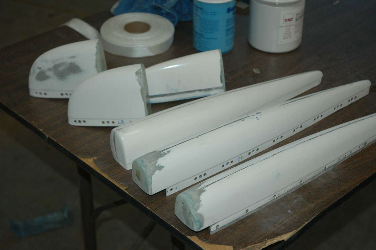
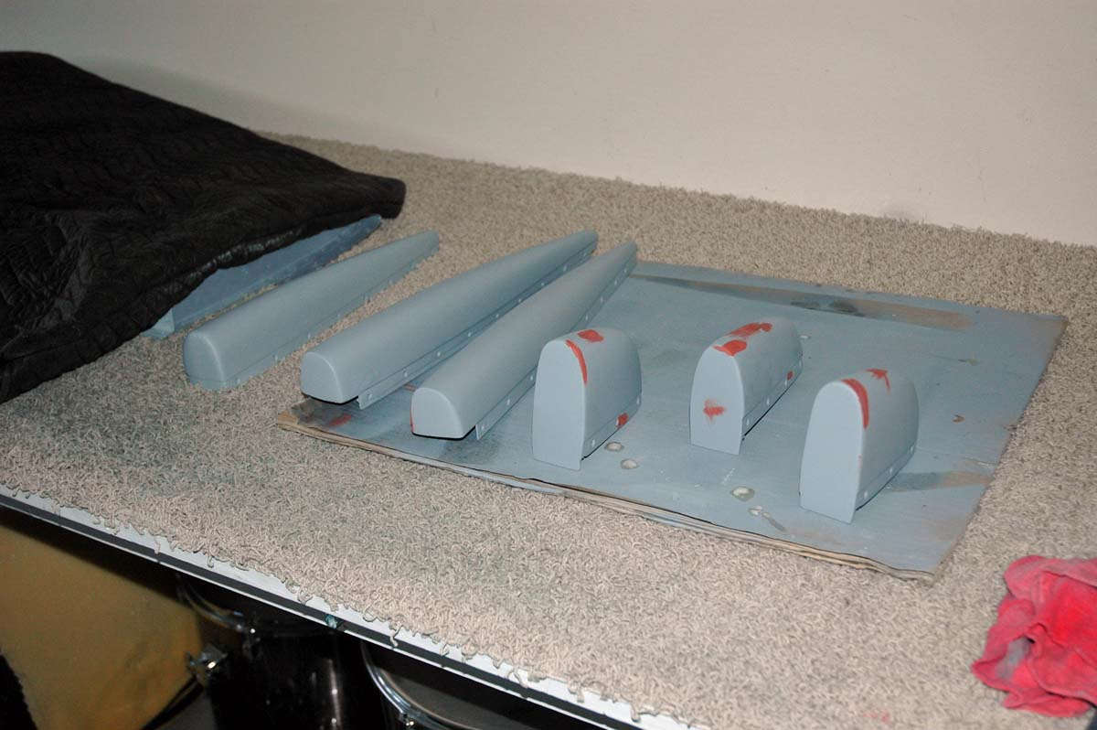
Did some sanding and other finishing work, prepping for the use of fill primer to reveal defects. Got to spray the first coat, revealing not a lot of problems but I fixed those with a bit of thin filler. Let that set up and sanded again.
And that's pretty well where I ended last week. I am pretty close to having the tips done. I have a few hitches still to overcome....I need to add some nutplates to the elevators to allow the mounting of washers to add weight to replace lead that I had to file off to get the tips to fit. Some other cosmetic efforts to finish up the effort, all of which I hope to complete in the next week or so. I also want to do a final adjustment to the rudder-vertical stabilizer hinges to set and square up the gap. More to come.
November 29, 2009
Bogged down in tips, what else can I say? After all is said and done, I'm glad that I used nutplates and screws to attach these parts, but it has been an unexpected challenge. Some of it was the nutplates...I worked too hard on them. Another part of the challenge is that the tips did not match up too well, i.e. rudder tip and vertical tip. Height was mismatched, then I compounded it a bit by lowering the river, so to speak, instead of raising the bridge. Specifically, as noted earlier, I lowered the vertical tip a bit instead of just raising the rudder tip a bit. I ended up lowering it too much and then, oh well...on to my travails.
I started by trying to fill in the area on the forward part of the vertical tip with some epoxy and microbubbles. Okay, then.
Another view with some masking tape placed to help me sand a bit.
Not happy with joint of the rudder tip either, I used some packing tape to protect the aluminum and filled this area a bit, trying to close the misfitting gap a bit.
Then I figured out I lowered the vertical tip a bit too much and had to raise the top contour a bit. Slathered on some more microbubbles. So, why do they call it microbubbles, anyways?
Another view...it was getting ugly out there.
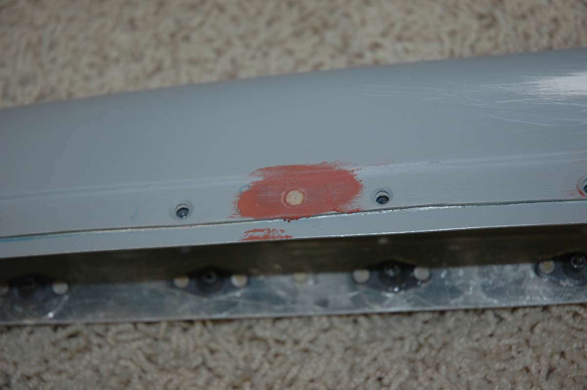
Meanwhile, I was doing some clean up work on the other tips, using a bit of glazing the rivets a bit as they don't set so well in fiberglass...not a neat countersink, as it were.
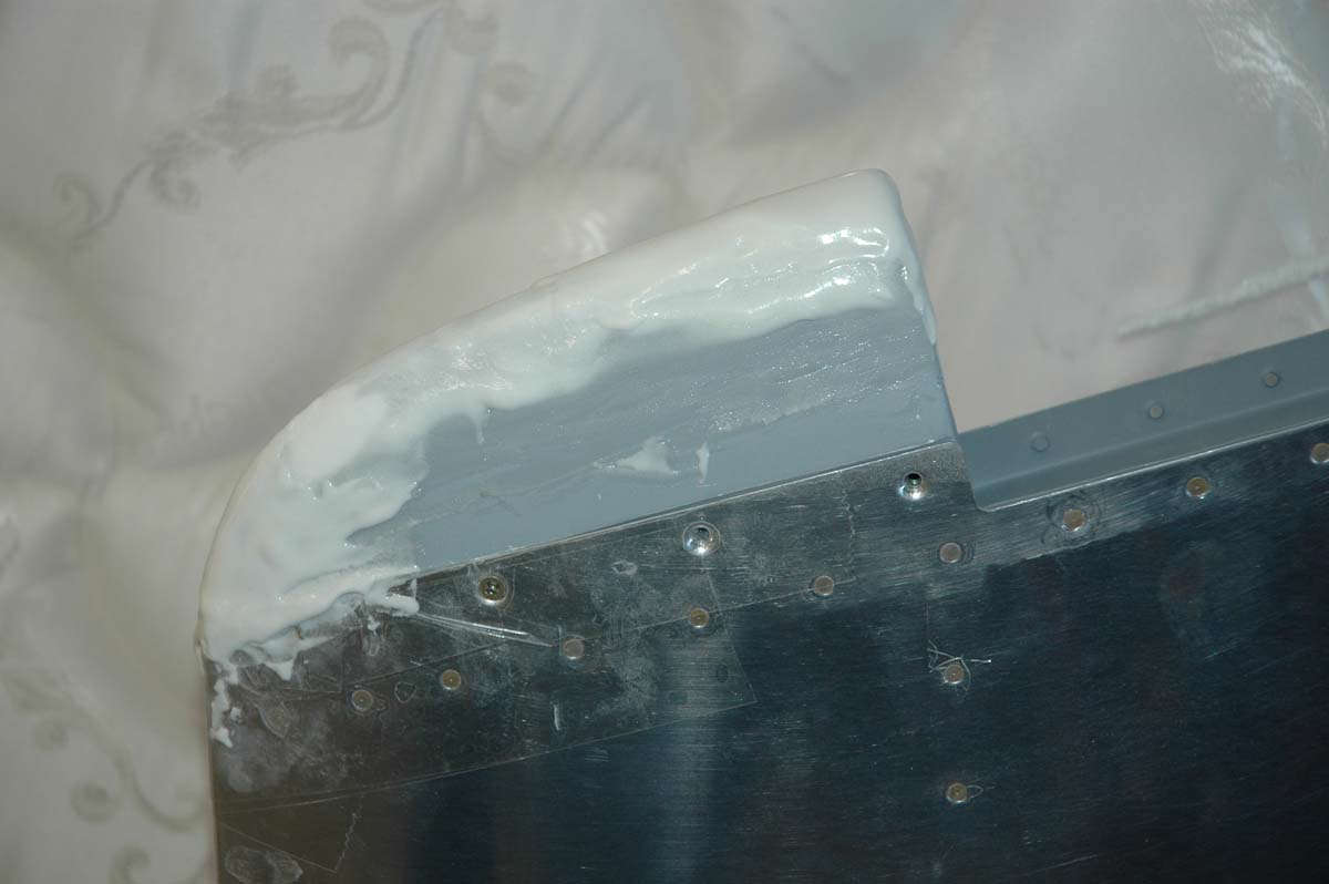
Kind of the raw version here, before cleanup. This is the elevator tip with the aluminum doubler, something that has caused me continual problems. Ugh. The problem was that the epoxy I used to bond the aluminum strip to the fiberglass can't take too much direct pressure before it gives way. Solved that problem by setting some rivets to hold the aluminum strip to the fiberglass. That, along with the epoxy, should beef it up enough. So, now we have the nutplates riveted to the aluminum strip that is epoxied and riveted to the fiberglass. I was (am) a hair's breadth from tossing the part and starting over with it, but we shall yet see. It might work out.
Back to the vertical tip, it's looking better here but when I matched it up with the rudder tip, the rudder tip was wider and didn't flow from the vertical tip. Had to reshape the vertical tip a bit, adding some more microbubbles stuff and more sanding. Kind of 'dig a hole and fill it with microbubble.' Understand this work was done over several days as you need to let this concoction set up overnight.
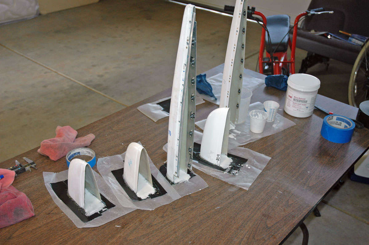
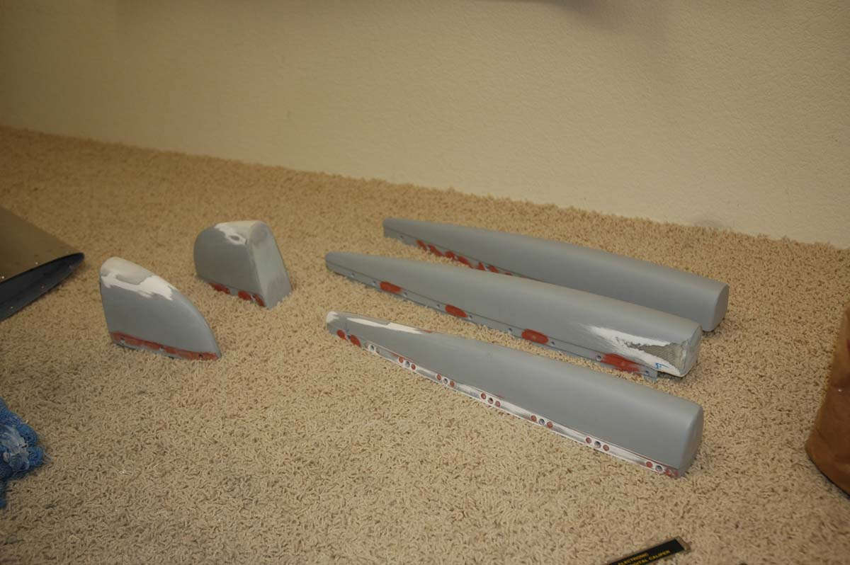
Getting close to being relatively happy with these tips. Just a bit more finish work and a final coat of sandable primer to finish them up.
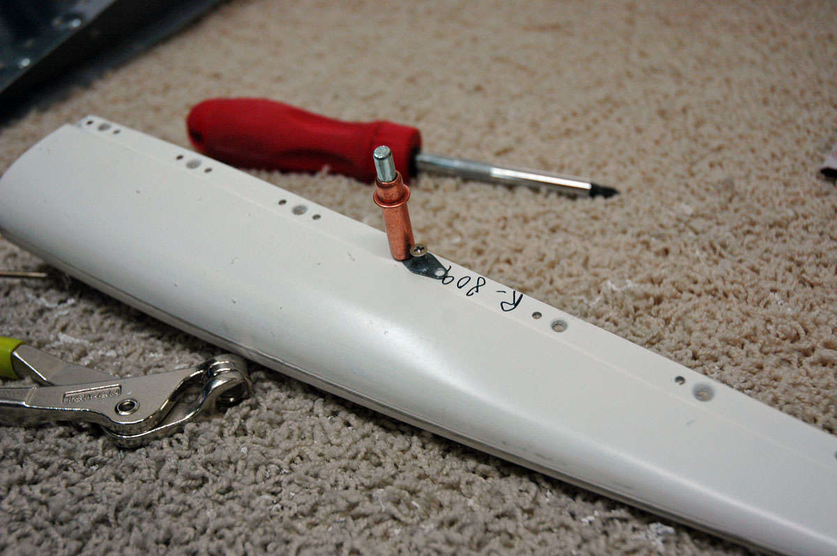
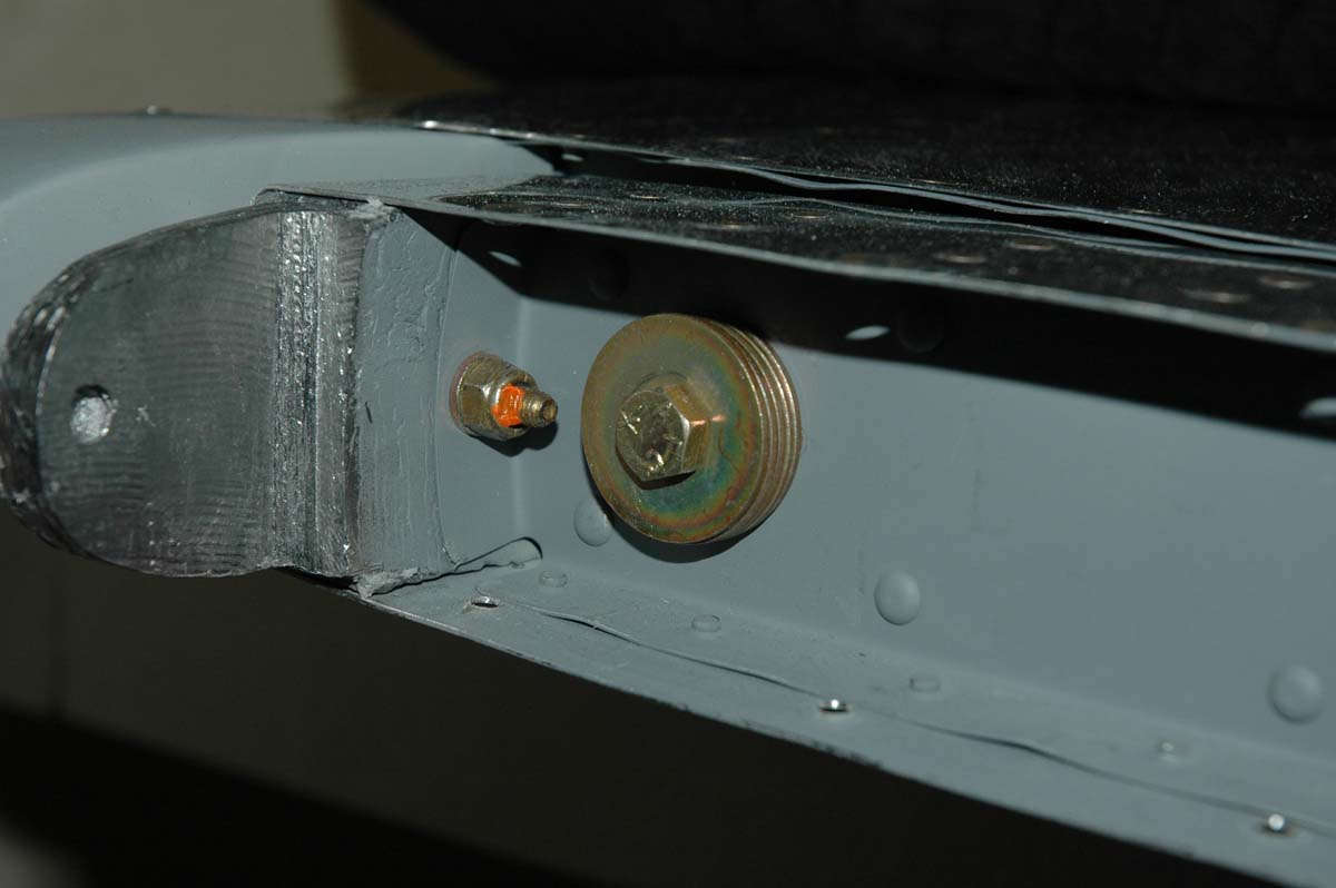
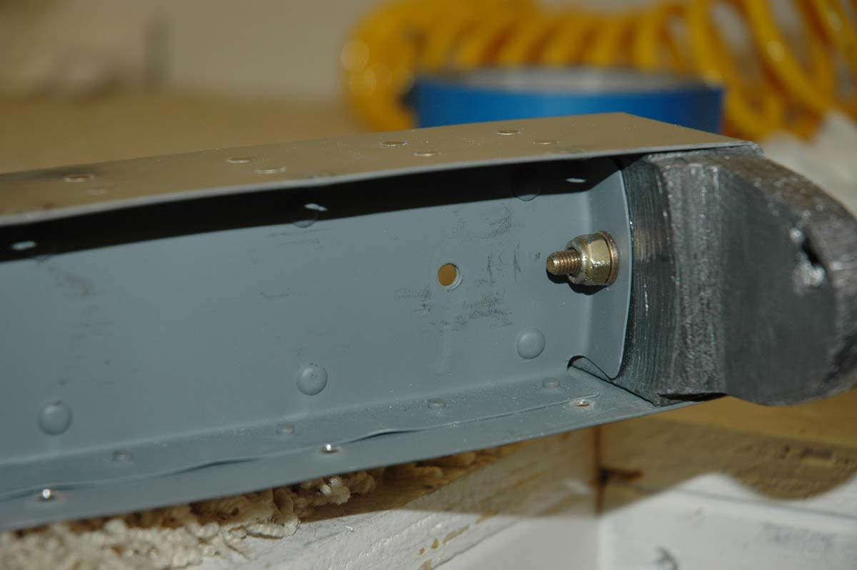
Taking a tip from Van's RV Forum's Rick6A, I used his method of adjusting the elevator counterweight. A K1000-4 nutplate is mounted to the small machining hole located just behind the counterweight after the hole is drilled out to 1/4 inch. Then, AN910-4 washers (the big boys) can be added to an AN4-4A bolt (on the other side of the assembly from this photo) so fine adjustments can be made to the counterweight weight. I did a static balance on the right elevator using this method, and can easily adjust it later after paint is added to the elevator.
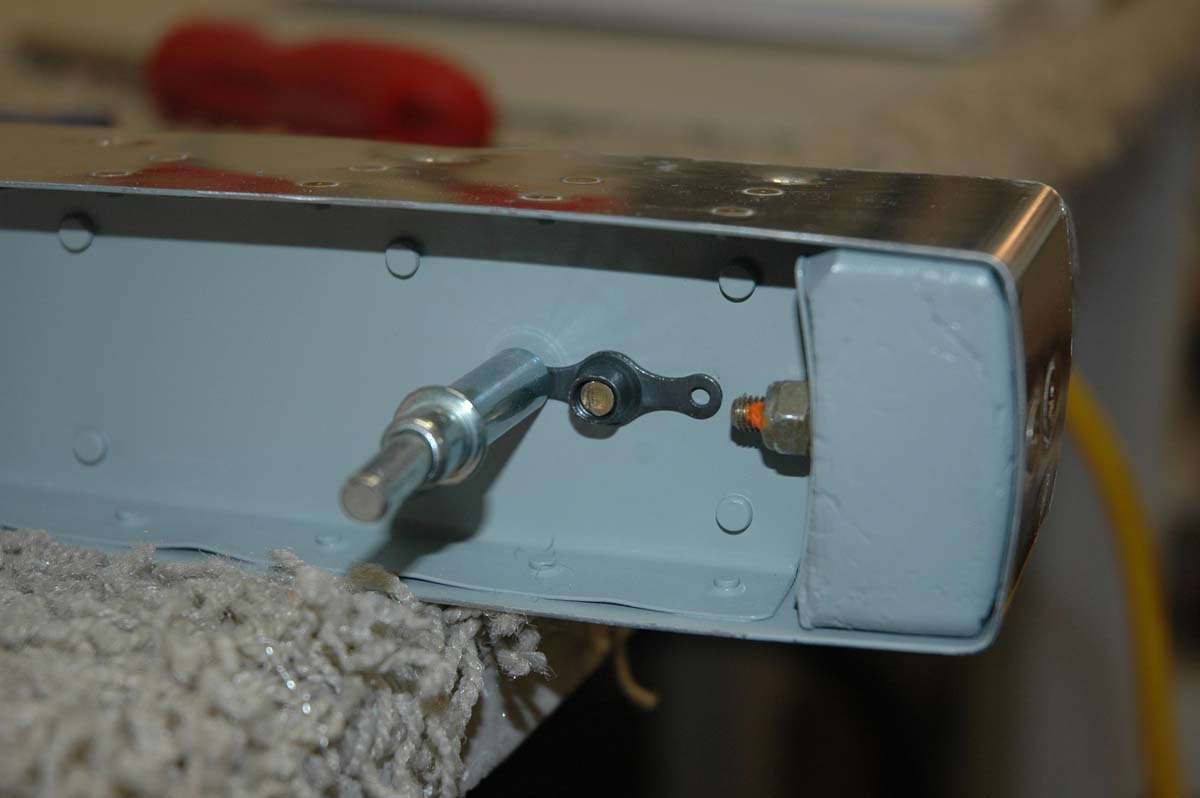
Here's a view from the other side with the bolt and washers installed. By the way, ignore the incorrect orange torque seal application. The torque seal should be applied to the nut-washer-skin surface, not the threads. Everyone knows that, right?
A note from experience: the written instructions don't mention it, and there is but a very small note on the plans (Drawing 5, E-714 Trim Detail) that indicate that only the counterweight for the right elevator is trimmed down. The left elevator counterweight is left untrimmed to account for the weight of the trim tab servo. It would have been good if I had known this before I trimmed the left elevator counterweight and installed it in the elevator. I then had hoped my little washer trick would work here also, but I need about 14 ounces of weight. Each washer weighs, I'd guess, about 0.4 ounces, so that is like, maybe 34 washers. Hmmm. Plan B is to order another E-614 rudder counterweight and trim it down to install just behind the E-714 counterweight using AN4 bolts and AN365 nuts. Nuts.
So, that's where it's at. I need to install that cut down E-614 weight, do a bit more finish work on the tips, and then these two major subassemblies should be completely completed. Wings are scheduled to be here next week, so when I order the E-614 weight (today) I'll also order a few other parts....wing conduit for wiring, some hardware, and maybe some Pro-Seal for someday fuel tanks.
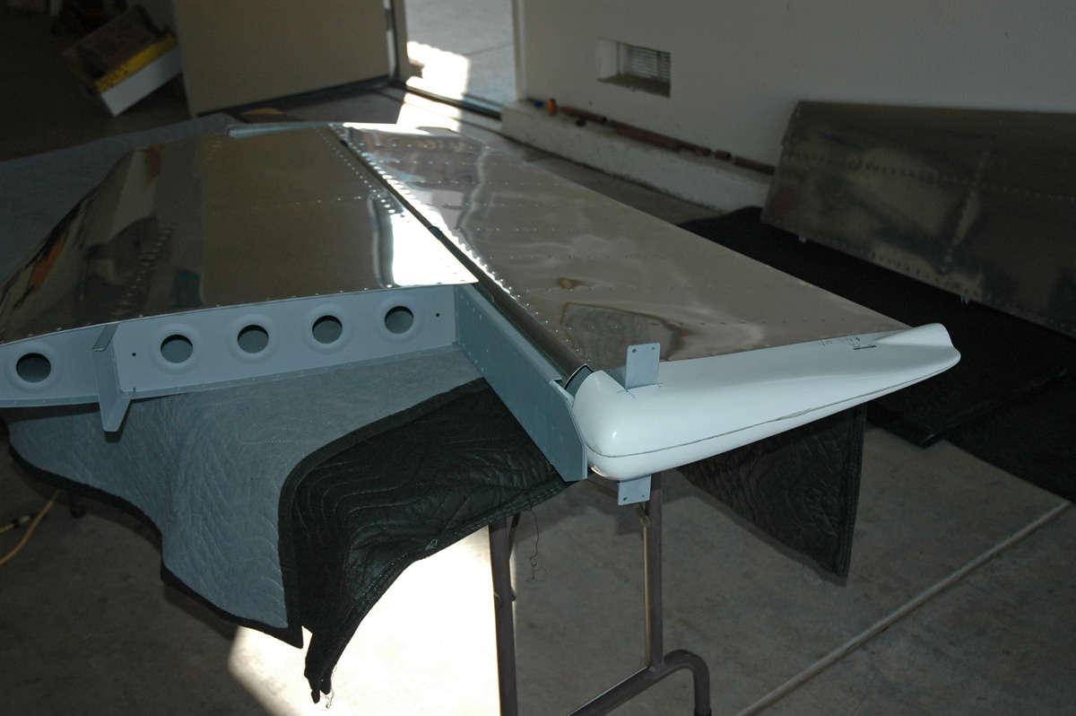
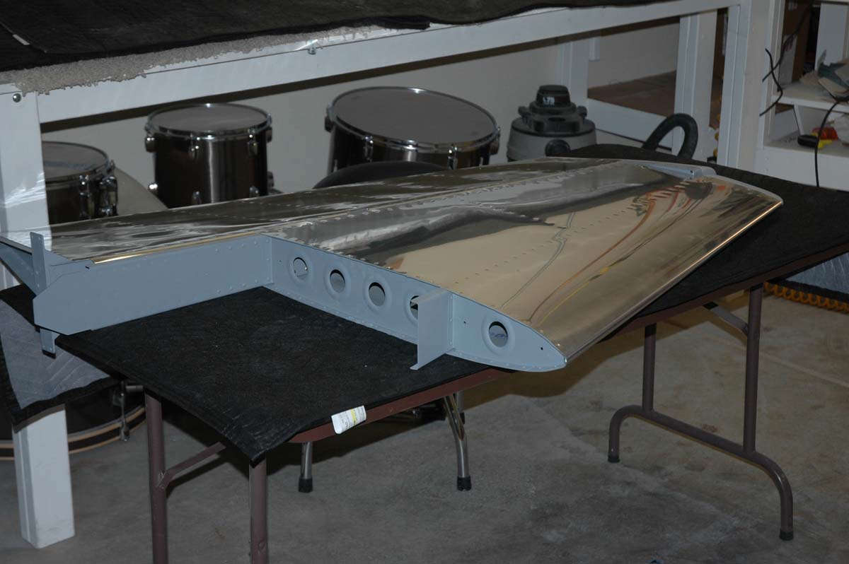
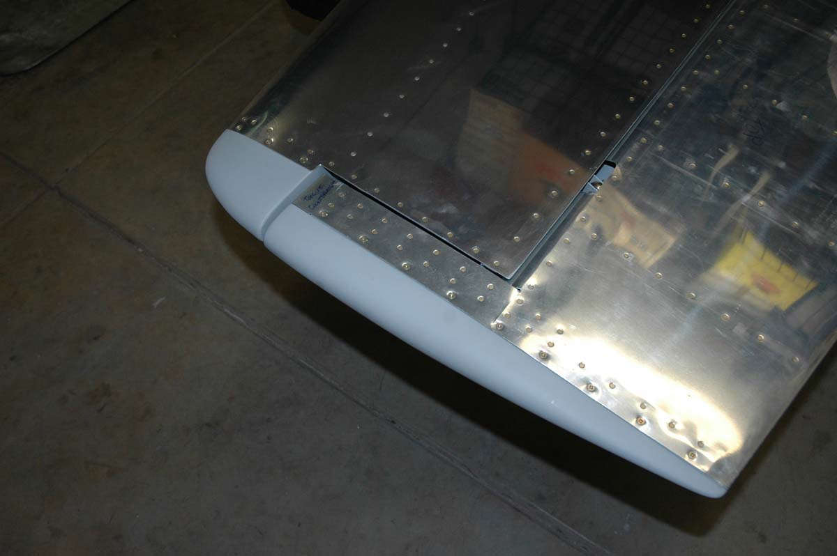
Here is the rudder and vertical stabilizer in that completely complete state, or just about. Always just about.
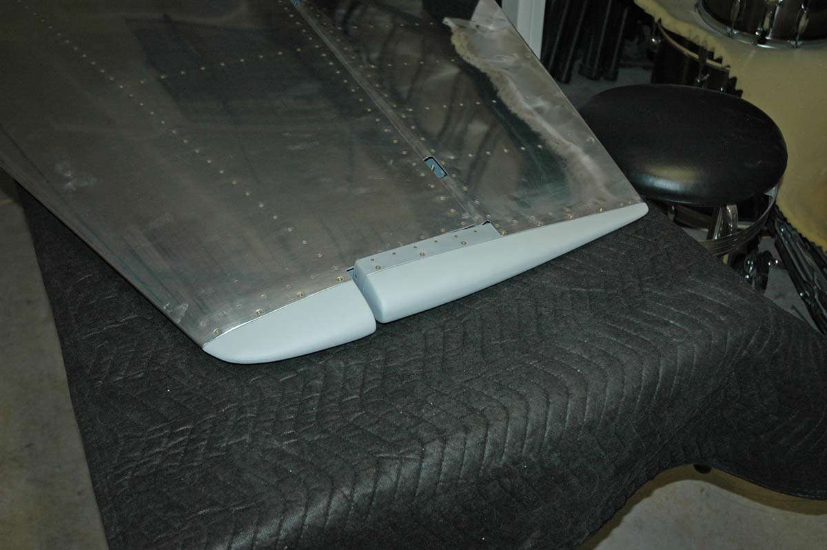
And one more.
December 7, 2009
Pearl Harbor Day, and don't you forget it.
Well, after eleven months of work, I finally finished the empennage. Doing the fiberglass tips was a good thing, but the finishing process caused the whole empennage process to sort of end with a whimper. I can't really point at anything significant done this past month except for a couple of pieces of fiberglass screwed onto the ends of the different parts. Big deal? Well, it works for me and I'm pretty happy with how it all turned out. Maybe a bit more work to do in prep before paint many years from now, but that will be then. This is now.
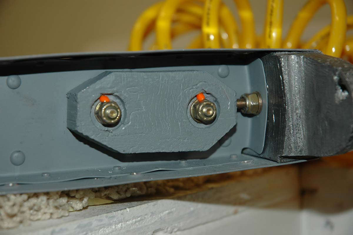
At the end of our last episode, I had ordered an E-614 counterweight from Vans, along with some associated hardware. It showed up a few days later, and I took the 24 ounce weight to one of my expert advisers (Mr. Greg) who happens to have a band saw just in front of him. We cut this thing down to about 16 ounces, leaving two ounces to play with with my file. Which I did. Here is the weight at about 14 or 15 ounces.
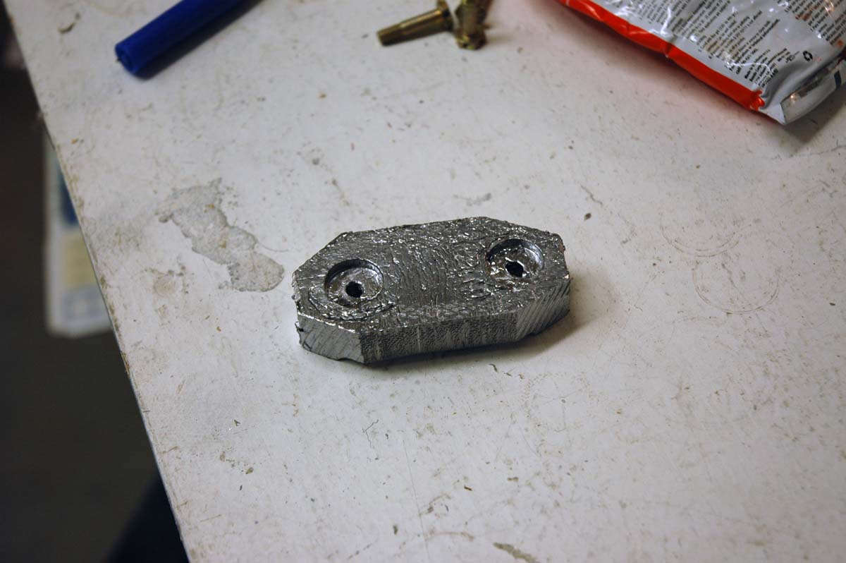
And here is where it is going to go, bolted in just behind the normal counterweight that should have done the job if I had done a better job of reading the plans.
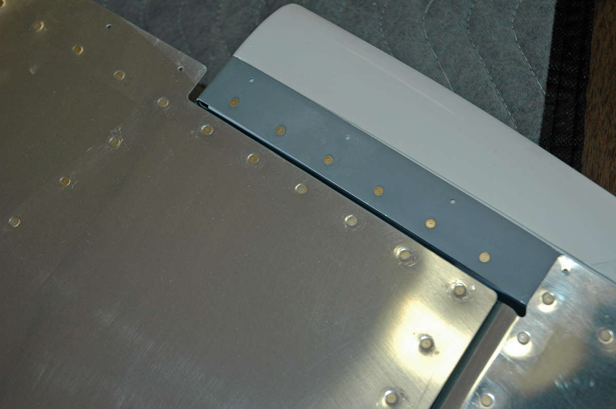
And here the deed is done. This thing is mounted on the side opposite of the elevator, so if it happens to come loose it will just rattle around in the fiberglass tip. It's torqued down "right proper" but it will no doubt be an often checked item. Good thing I made the tips removable, eh?
So, when all is said and done, the fiberglass tips are screwed down. It looks better when it's done, and it doesn't look like it should have been that hard. The trials and tribulations of the learning curve.
I admired my handiwork for about ten minutes or so. Looks pretty cool.
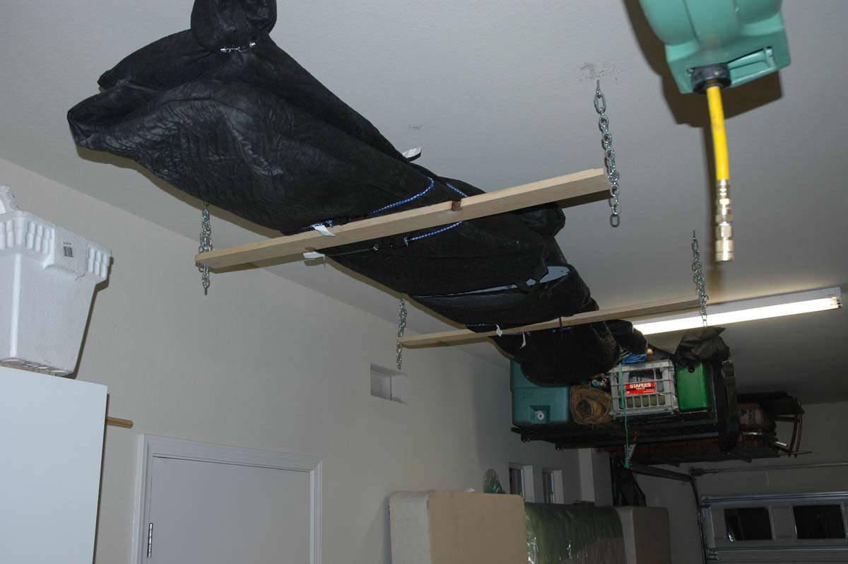
But, there was no one around to admire it with me and, even if there was, they probably would have just been polite anyways. So, I implemented Storage Plan A, which was to attach the elevator to the horizontal, store it from my little hanging shelf attached to the garage ceiling, and then store the rudder and vertical stabilizer stacked carefully above that. I thought about that for a few minutes and thought about just how many ways of something going wrong with that plan.
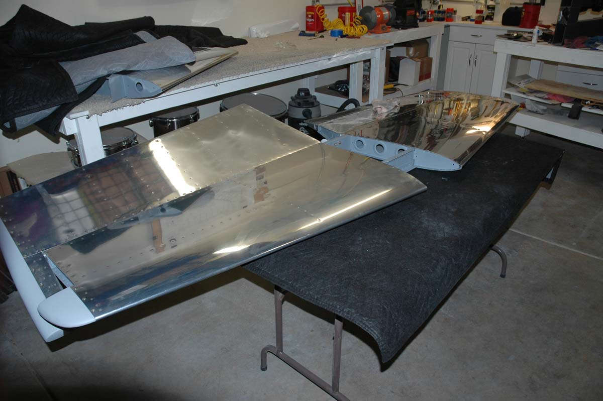
In the end, I carefully wrapped the horizontal stabilizer and hung it my little rack. Then, I stacked the elevators carefully above that.
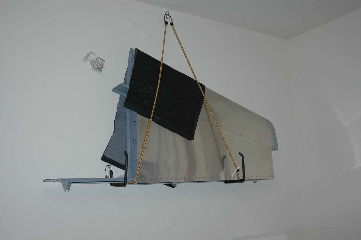
I looked around on my garage wall and found two places to hang the rudder and vertical stabilizer from.
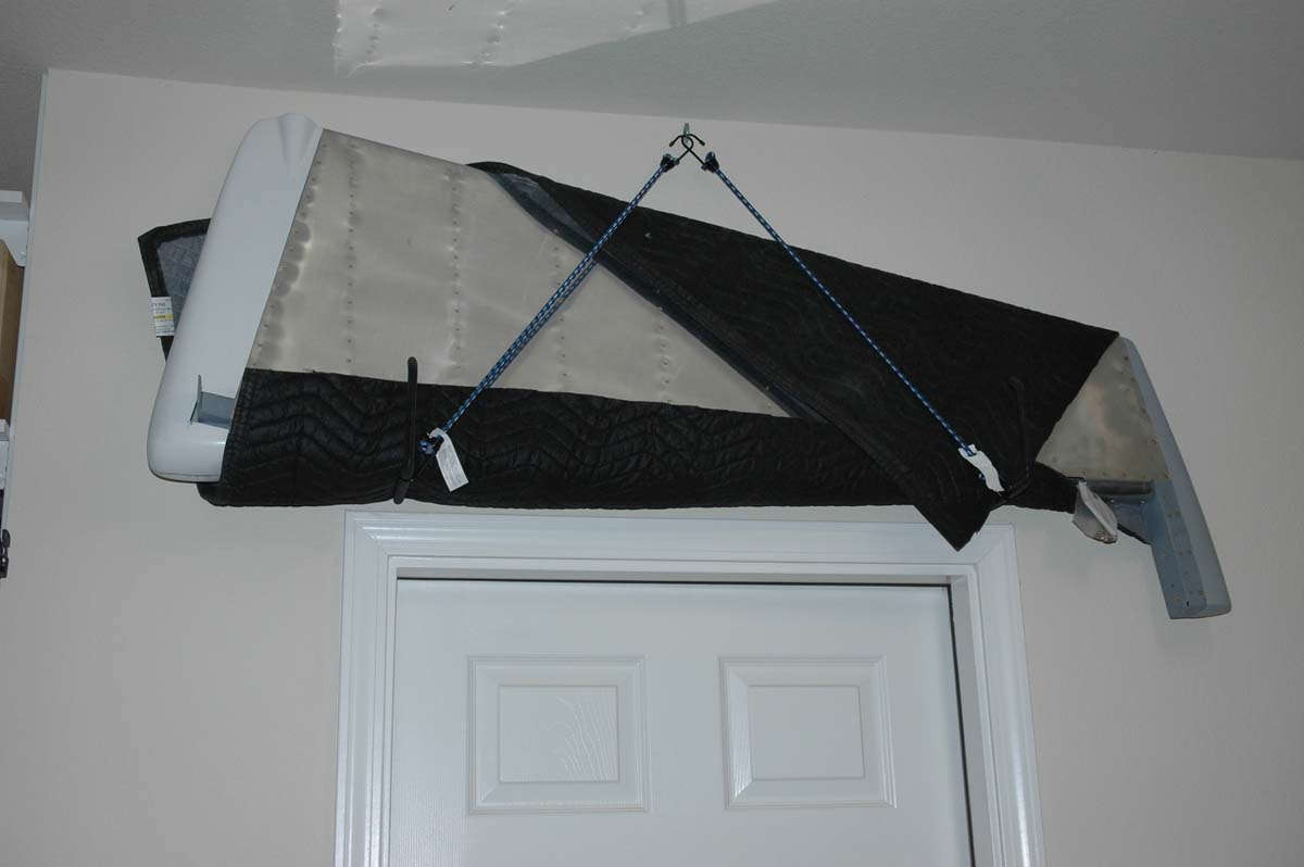
And there they shall sit for probably five years, maybe less if I get rich or have much more time to devote to building this airplane. They will come down next year some time, as my EAA Technical Counselor suggested we combine the final inspection of the empennage with the wing inspection when the wing is pretty much assembled except for the bottom skin. And, maybe before that if need be. The main thing is that it is done and I can now move on to the wings. The wing kit, by the way, should arrive this week, so stand by for more. Don't expect to get too far into the wing until January, but maybe inventory and organize for the next few weeks. Should be fun.