|
Working on the Main Wing Structure |
February 21, 2010
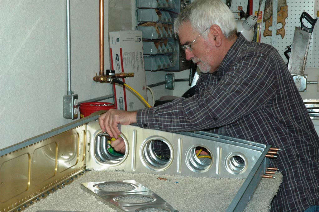
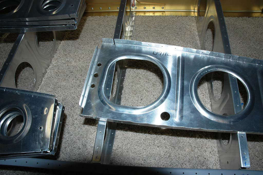
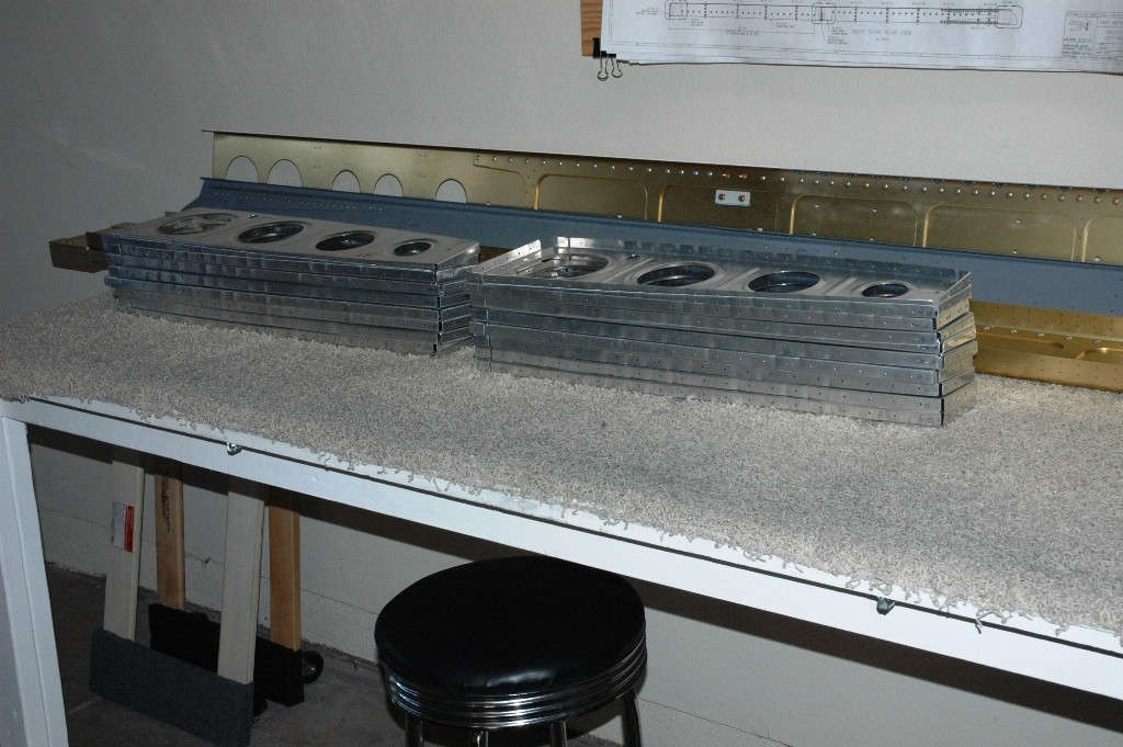
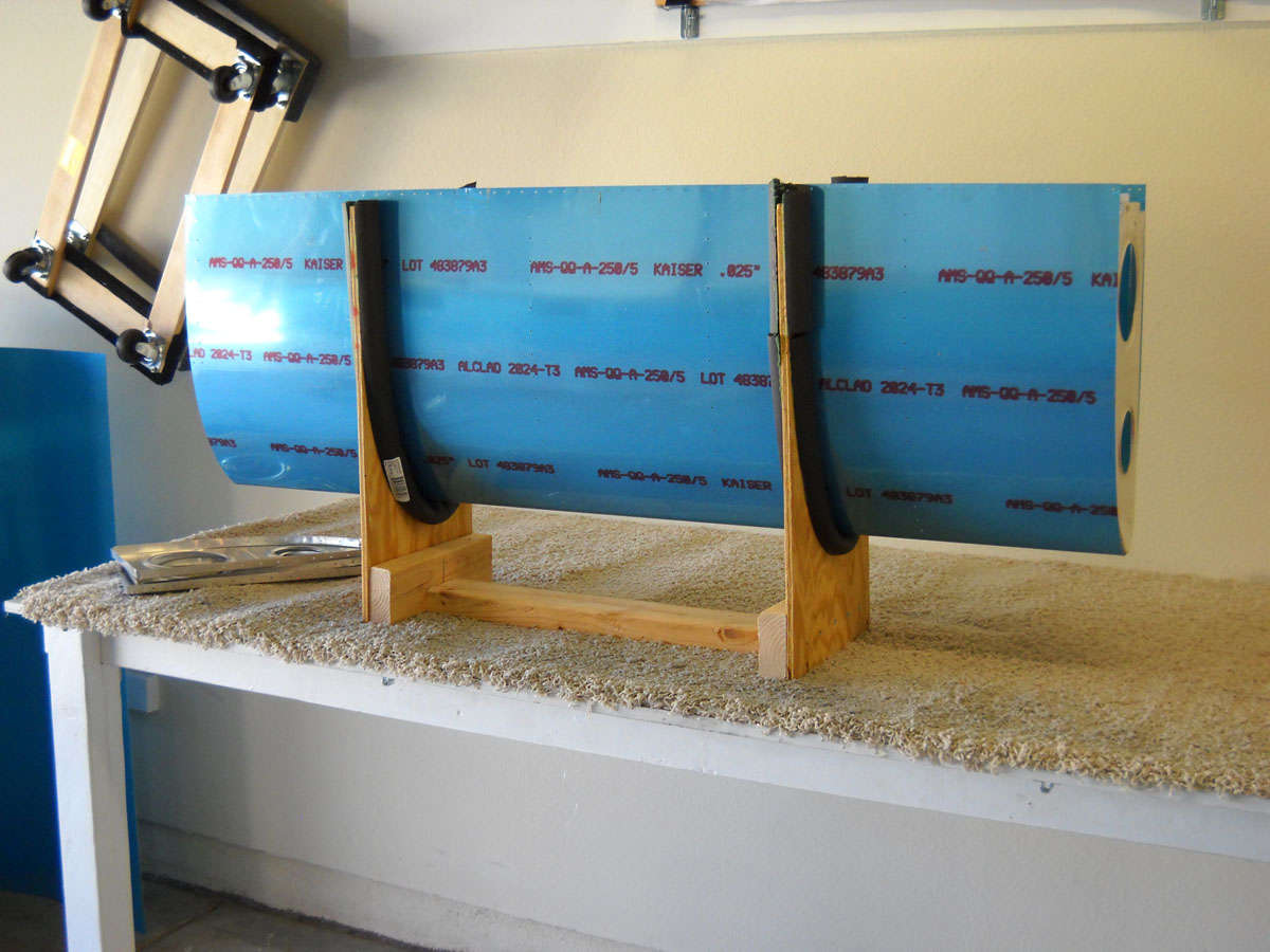
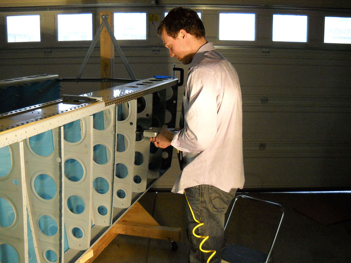
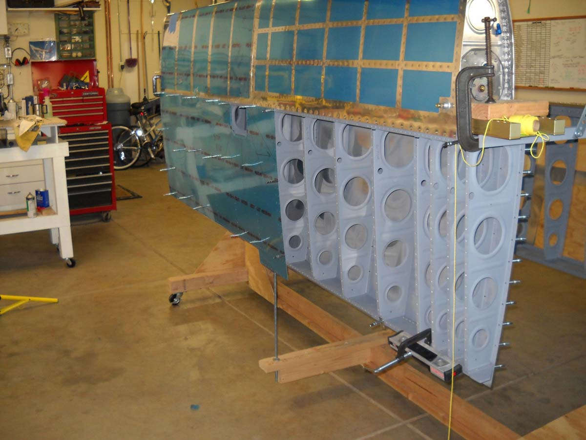
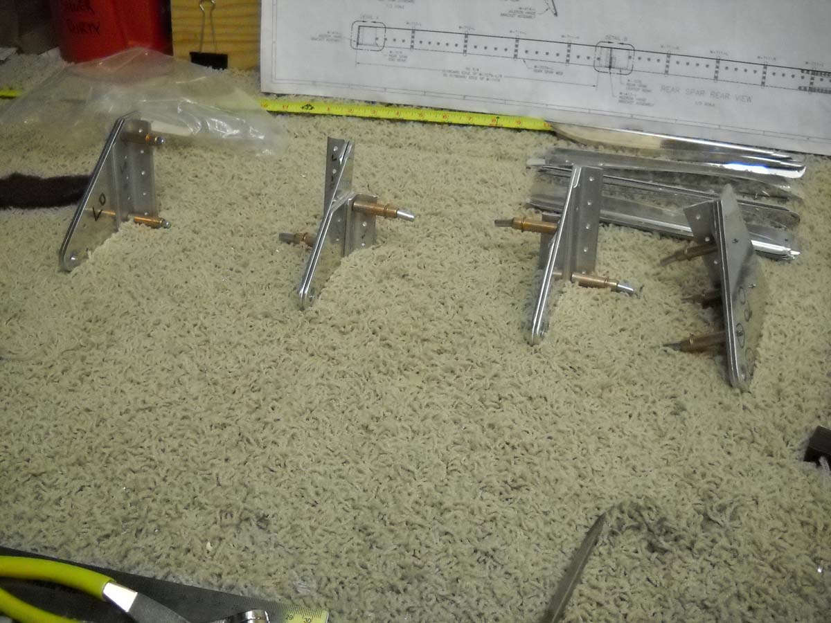
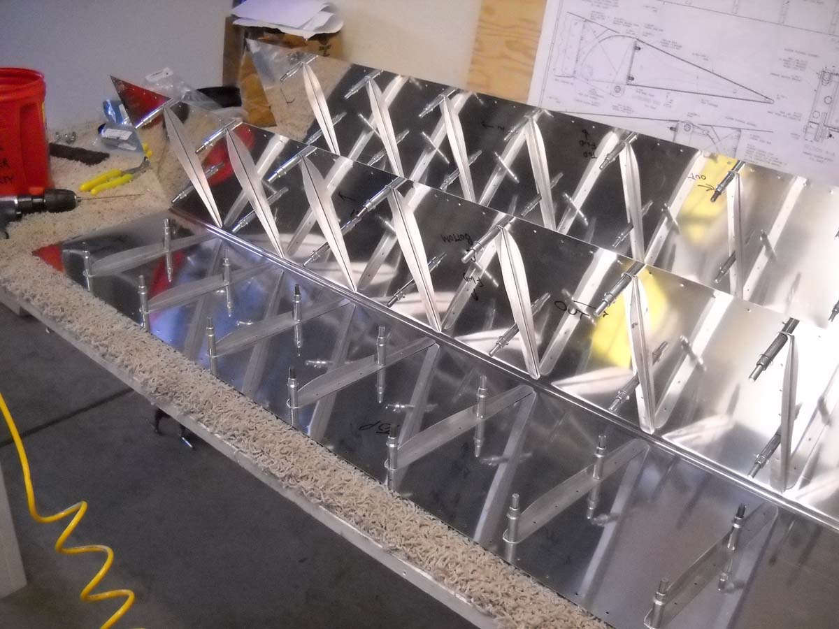
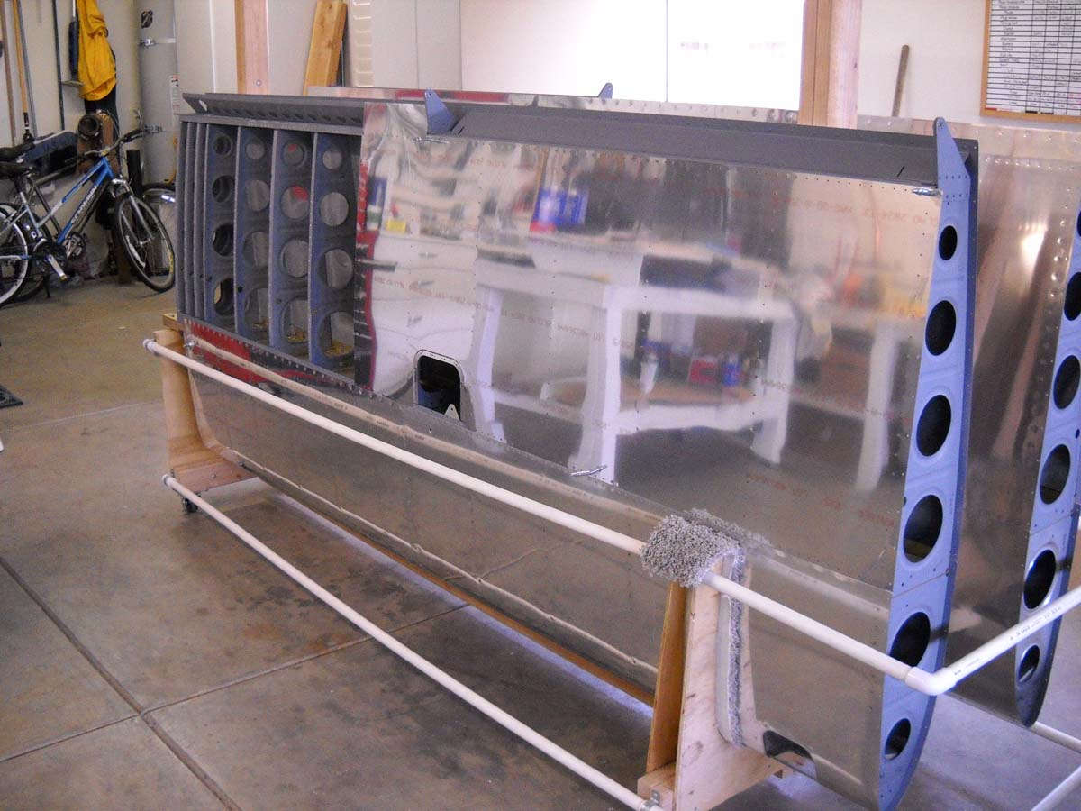
So, this past Saturday the wing spars, all four of them were completed and we moved on to the rib prep work, moving toward the assembly of the main wing structure of each wing. Here, looming over the second rear spar, are the wing ribs. Every site I looked at commented on what a dreary drag it was to do the spar prep on all these ribs so I knew what was coming. But, except for a few of the on-purpose missing rivets, the four wings spars were complete and ready to go into the wing.
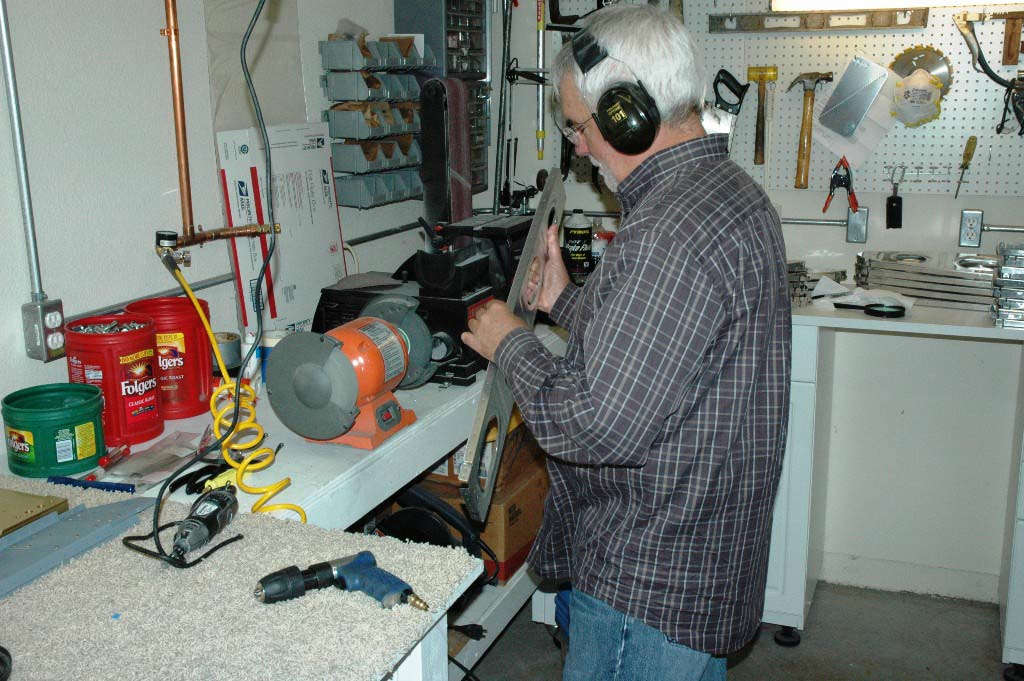
So, Saturday came and my friend Bill Reid came over to play. We've talked about this little project of mine and he's followed it with interest. He likes airplanes and has seen some other kit planes under construction. He's not a pilot but he has a motorcycle so that's almost as good as having an airplane. So, I lured him over on the pretext of helping. Little did he know we were going to do rib prep.
But, before we got into that, Bill did squeeze the remaining rivets to be done on the rear spar. He practiced a bit on some scrap and then went at the spar rivets like he'd been doing it for a long time. Spars are done.
As much fun as I knew the ribs were going to be, I decided to break the job into two phases. My hoped-for goal for the day long session on Saturday was to prep all the main ribs for both wings. If we got at least one of the wings done we would cleco together that wing section anyways, just as a "big-picture" reward. Each of the wing and leading edge and fuel tank ribs need to have edge finishing, flange straightening, and fluting done.
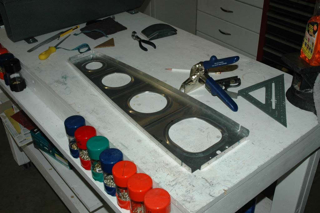
Bill and I got a little mini-production line thing going. He did the edge finishing on each rib, using a die grinder with a Scotchbrite wheel for the lightening holes and a Scotchbrite wheel for the outside edges.
Then I took the rib and did some fine edge finishing using a Dremel tool with a Scotchbrite attachment and/or sandpaper and/or a file to get some of the finer edge work done. Then, I squared up the flanges using an edge seamer and my cardboard square (easier on the alclad surface than a metal square). Then I used the fluting tool to flatten the ribs and make them straight.

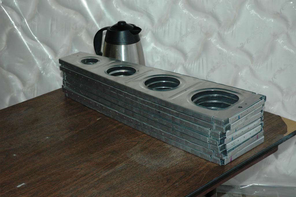
We worked through the ribs one at a time...the whole thing took about six hours for the two sets of main ribs...twelve man hours of work, basically. Here is one stack completed.
The leading edge and fuel tank ribs are set aside for another day. I can work on those slowly in little parts as the main wing structure comes together. I'd rather take small bits of that workload on if I can break up the effort a bit.
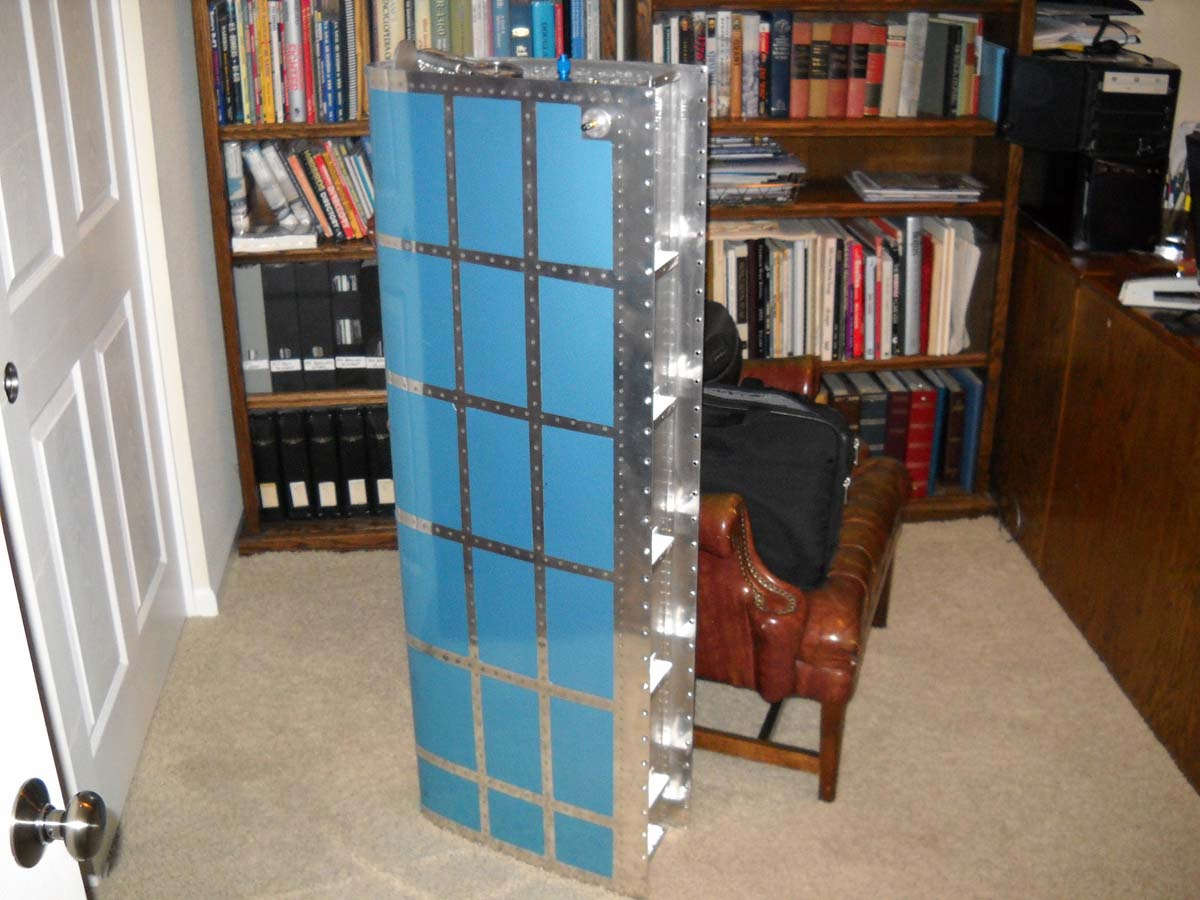
So, we did get through both sets of main wing ribs. Thus, as the work day drew to an end, we did cleco together the left wing structure. I had already put the ribs in order so it was just a matter of laying the ribs into position and, after double checking the orientation, clecoing them to each spar. Bill enjoyed the cleco experience.
Okay, that does just look so cool. It actually is a wing. Pretty solid even without skin, at least in my humble opinion. Those Vans guys know what they are doing. And having the extra set of hands made the process go much quicker...thanks Bill and standby with a bucking bar. We'll talk....
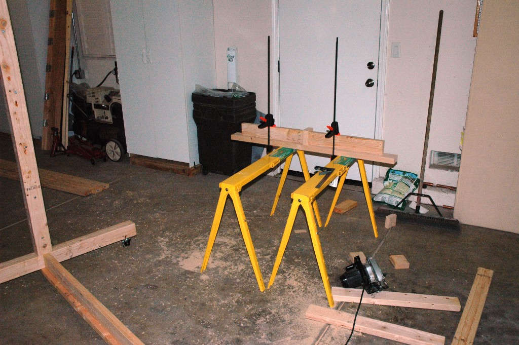
It is bigger than I thought once it is assembled. Next step is going to be building the wing stand, perhaps next weekend. I've sketched out what I need. I can also plan a bit better for the pitot system and wiring.

I've been reading up on both systems and have pretty much decided to go with the Dynon pitot tube and AOA (and thus Dynon avionics) and the SafeAir1 pitot-static system and pitot mast. Add to that Duckwork lights and Whelan position lights/strobes and you have a plan of action and a big cash layout. Okay, get the order book ready, guys.
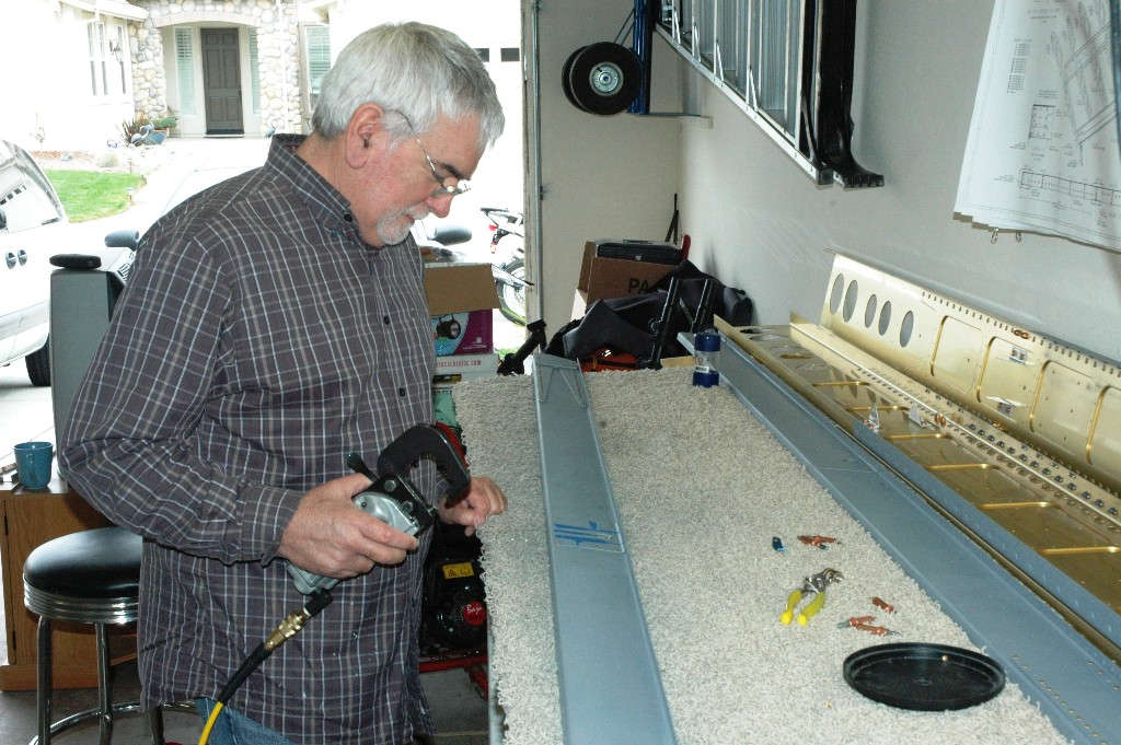
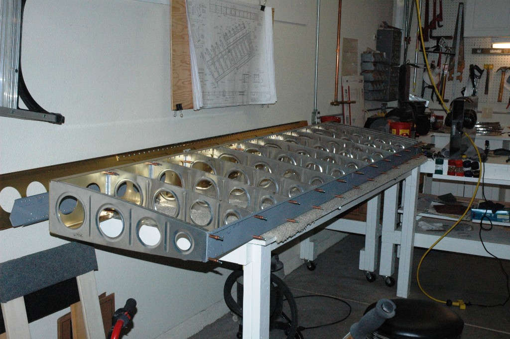
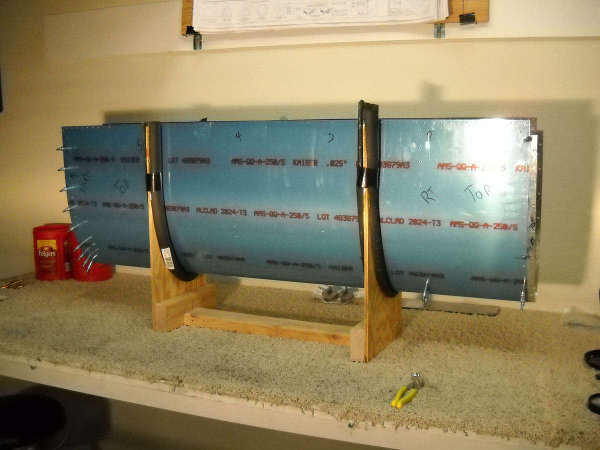
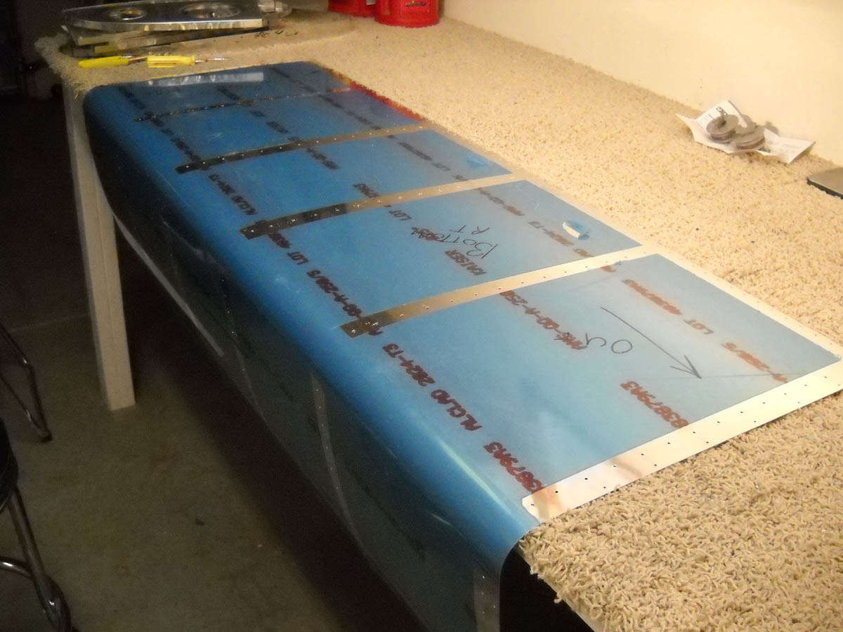
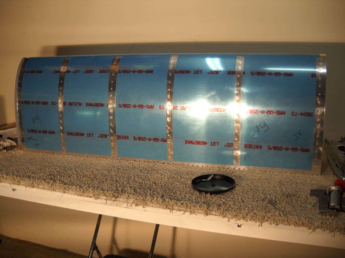
I do some Learjet flying for the next few weeks...not sure how much work I'll be able to get to do on the wings, but here is the better part of the left wing on my workbench so I can stop and ponder the work in progress every once in a while when I stop back in town. Pondering is not a bad thing.
March 15, 2010
I can't believe that it's been three weeks plus since I updated this page, and on the off chance that someone is actually visiting and reading this site, I thought I should add some update stuff. I have not had much chance to work on the wings recently....too many other things going on. My oldest son Adam bought a house on an acre of land, both of which need a bit of work so I've been pitching in there. That, plus much traveling, both personal and professional, have kept me busy. But, here and there, I have done some stuff.
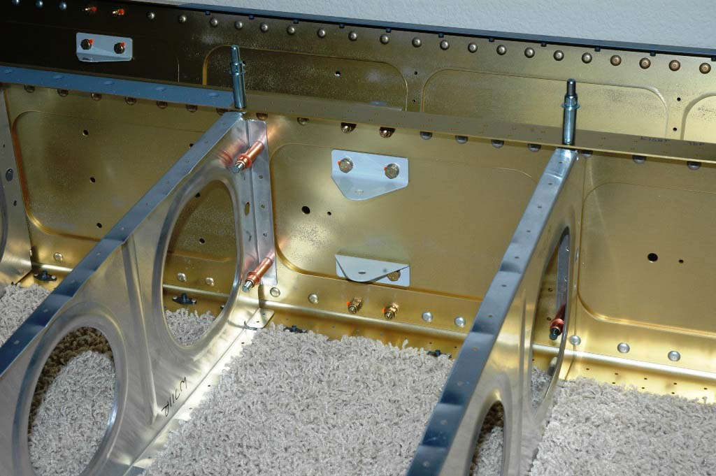
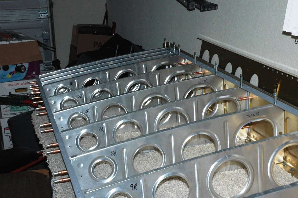
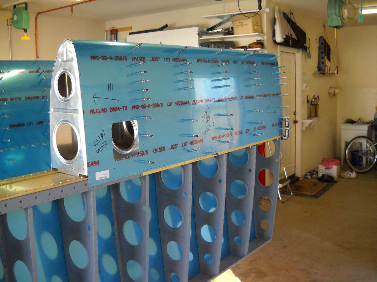
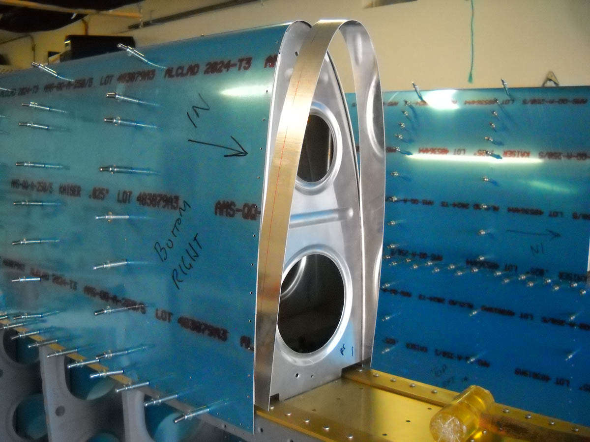
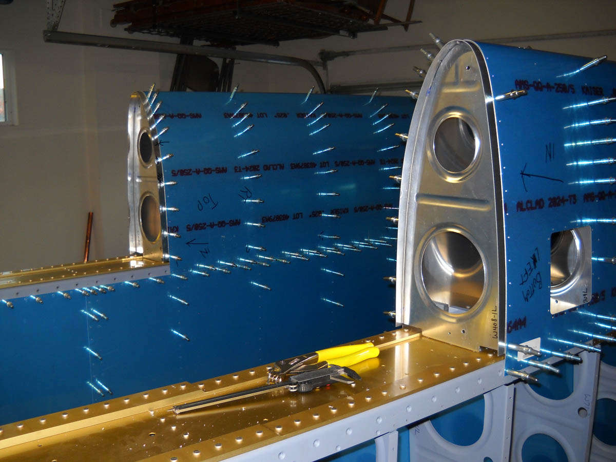
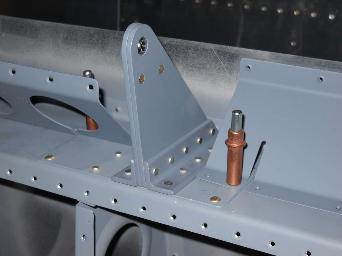
I assembled and drilled the right wing main structure.

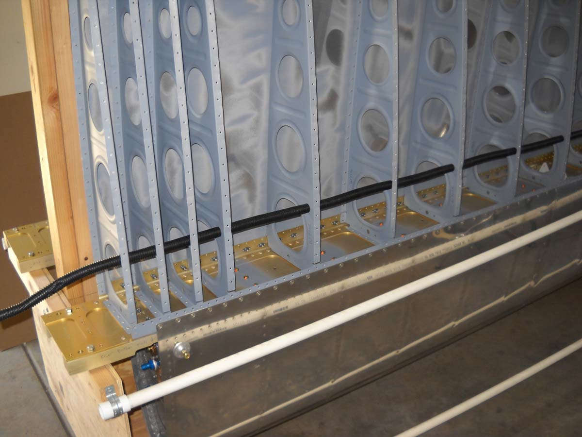
Here are the ribs clecoed to the main spar with the aileron bellcrank mounts also shown.
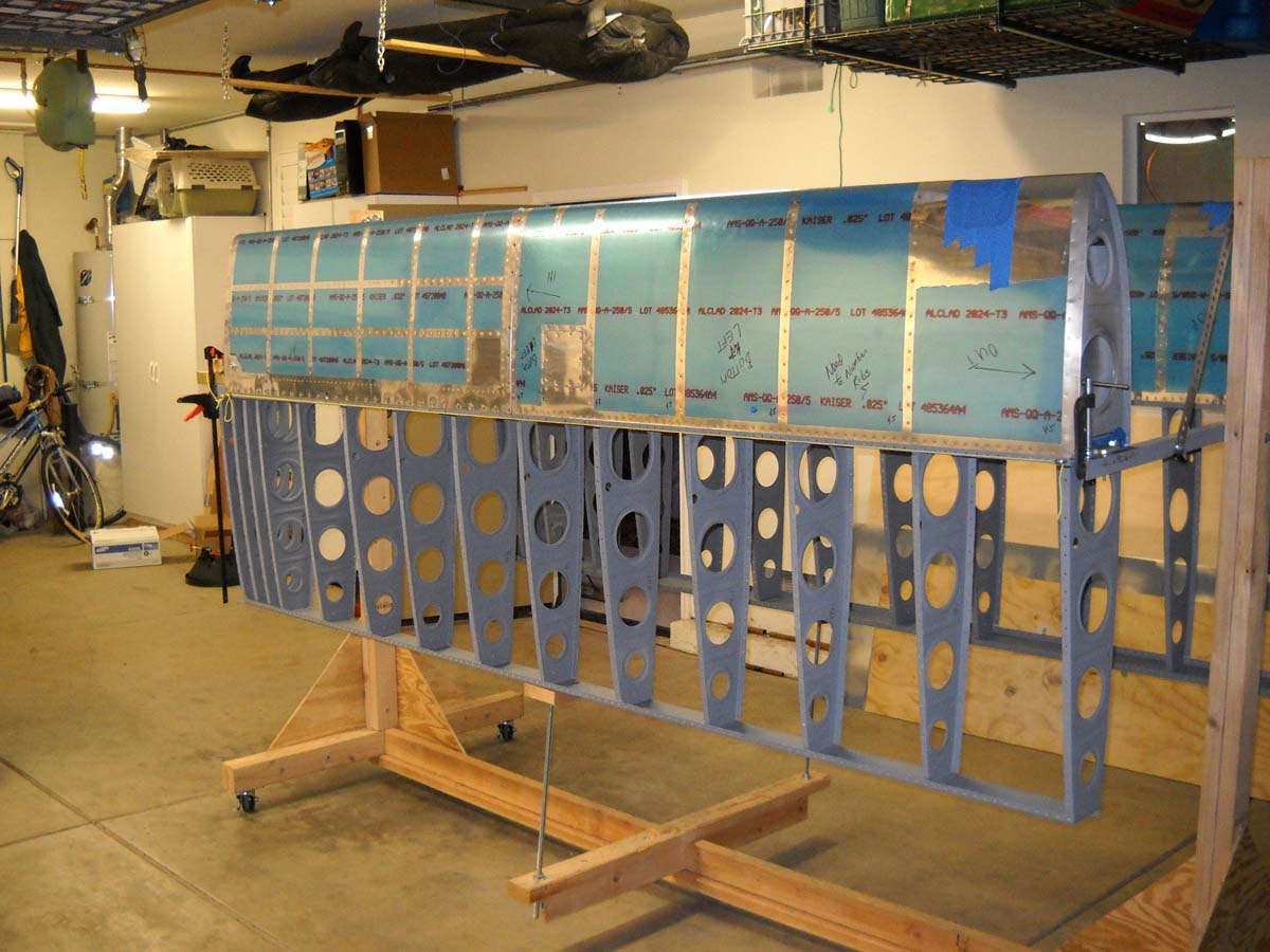
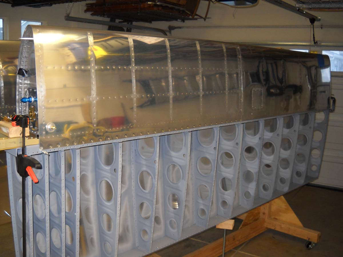
And, a view of the wing structure all assembled after drilling the ribs to spars to size.
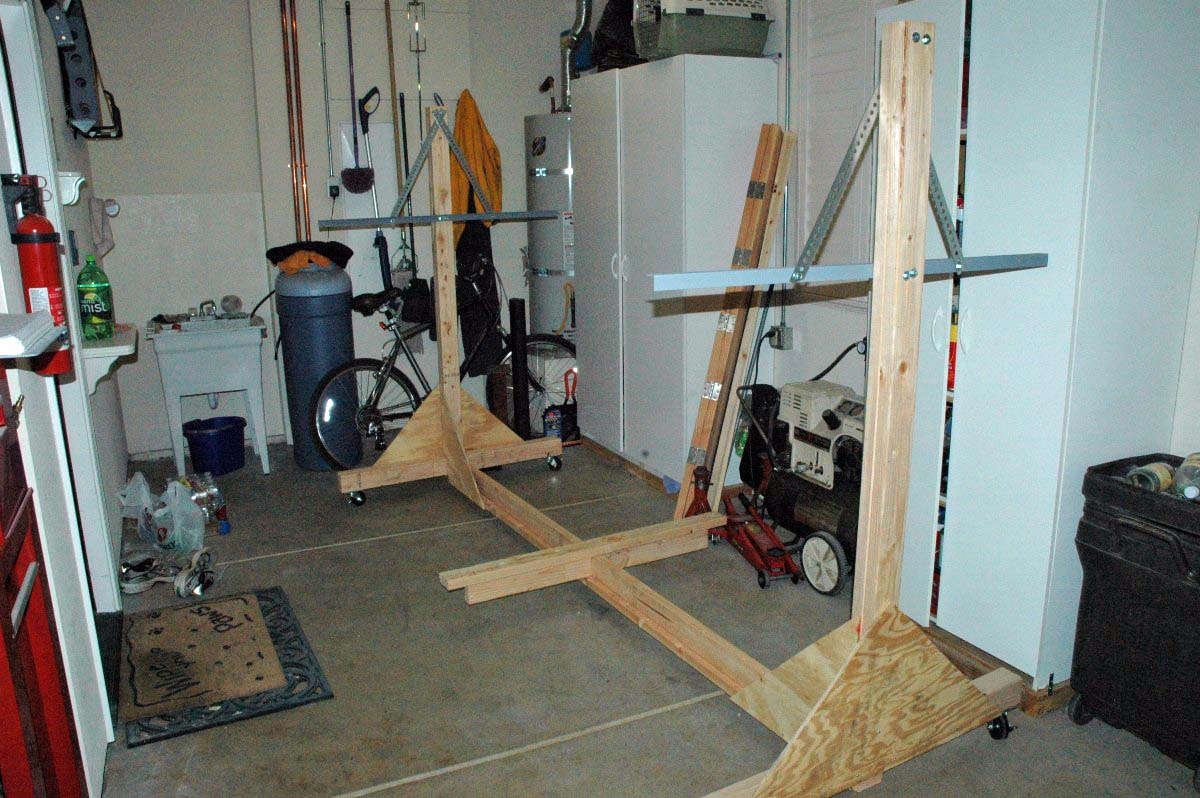
Then, it was on to the wing stand. I want this stand to be mobile and to hold both wings. I looked at some examples on a few websites and borrowed what I liked from each. Some guys anchor them to floor and ceiling, as Van's Plans show, but others have had equal success with mobile stands. With the wing structure and skins pre-drilled, the exact alignment of all the parts falls into place when the holes line up. Not to say I won't check things like wing twist and alignment very carefully.

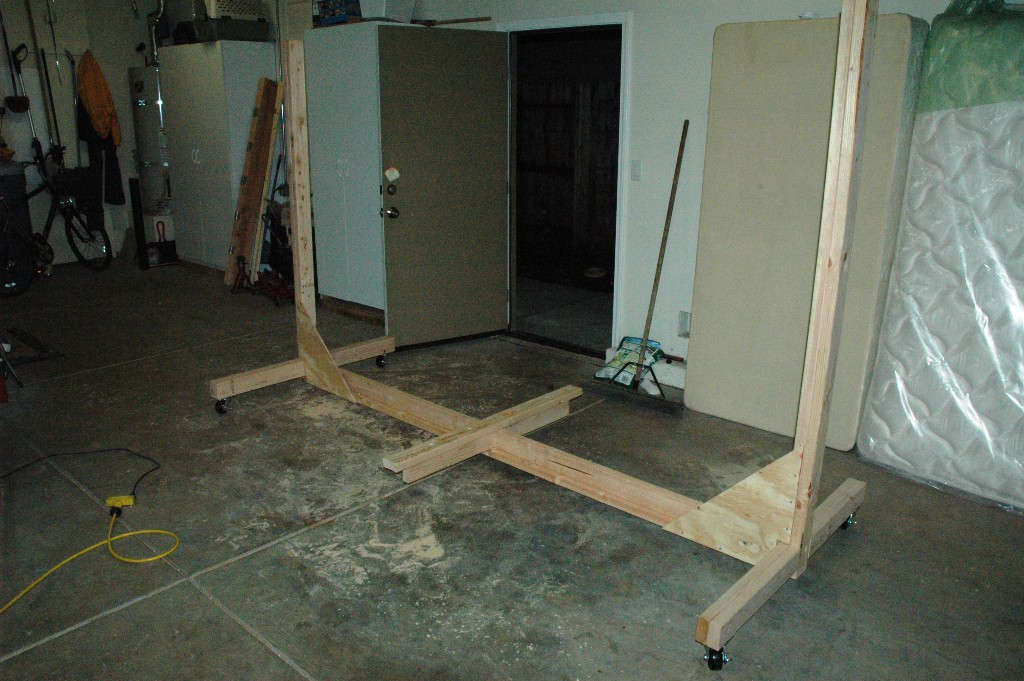
I used lag screws to assemble everything. I figure it will be tighter than nails and come apart easier later when I convert this thing to a wing holder.
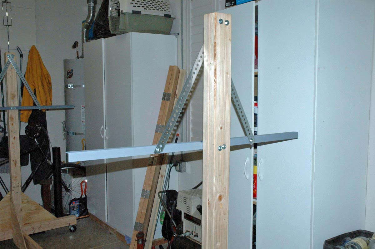
And here it is coming together 'right nicely.' This was like two weeks ago. The cross piece on the bottom will, if all goes well, hold the braces to bring the spar and structure up to level. We shall see.
Made a mistake here. Looked at Home Depot at the angle iron. Bent and twisted, trying to be a bit cheap and still rigid on the cross braces. After I got it home and cut up right, there was too much torsional twist...not rigid enough. Penny wise and pound foolish, I will need to replace this angle iron with thicker stuff. More bucks.

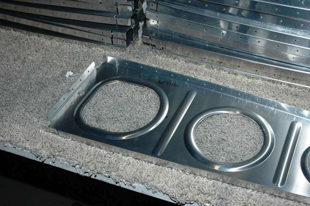
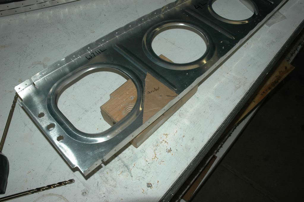
While I pondered that little error, I started working on drilling out holes for conduit and the pitot/angle of attack air lines. I decided to go with the Safe Air pitot static system and pitot mast, based on the recommendations of many and a close look at what they offered. Paid money, received pitot static system with much tubes and other stuff. Drilled, as per Van's Plans, a 3/4 inch hole in each rib for the Van's conduit to run wires to the wing tips and mid wing point. Drilled out tooling holes on the forward edge of the rib near the flange where it attaches to the main spar for the static and angle of attack line.
I am a shameless copier of good techniques, including using this little cardboard template to position the conduit hole at the same point on each rib.
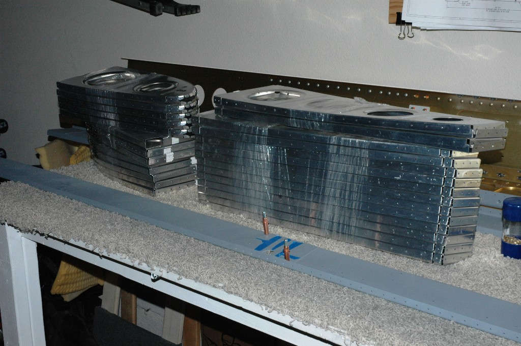
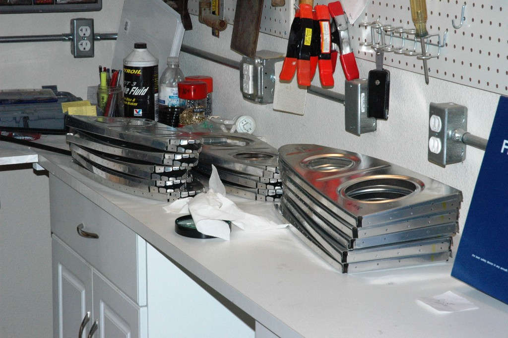
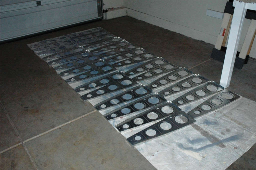
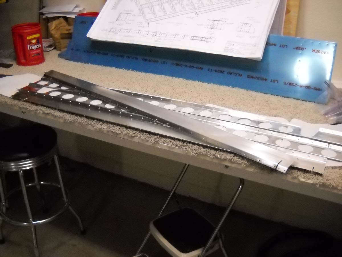
So, soon enough, there are all the main ribs on the work bench ready for final preparations for priming.
Numerous hours of deburring and final edge finishing led to several hours of carefully washing each rib in soap and water and then drying and then blow drying and then stacking carefully for priming.

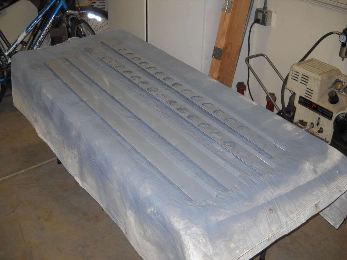
Here they all are laid for a day of drying, then on to Napa 7220 priming.
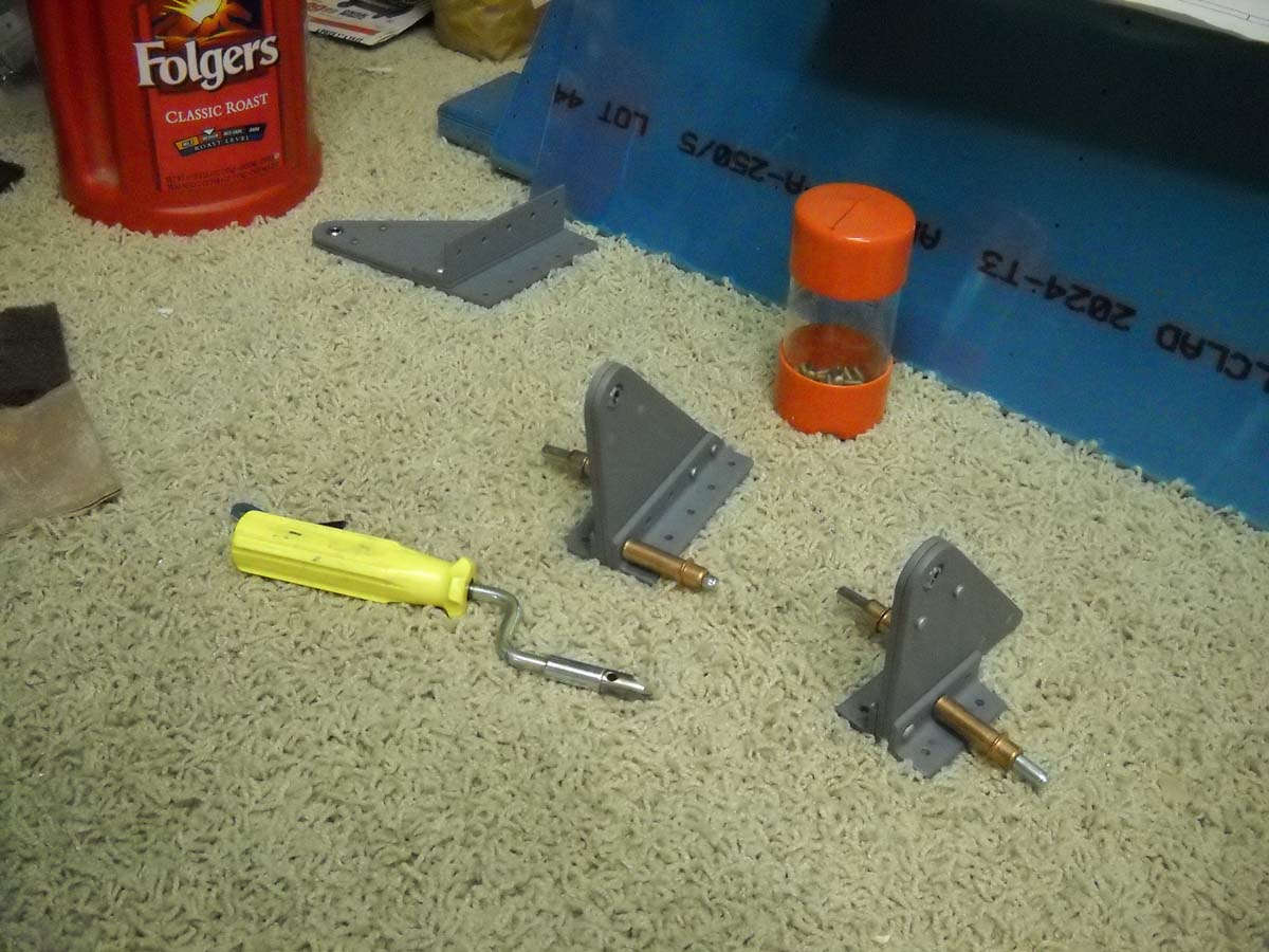
This past weekend I primed the right (or was it left?) ribs and stacked them here.
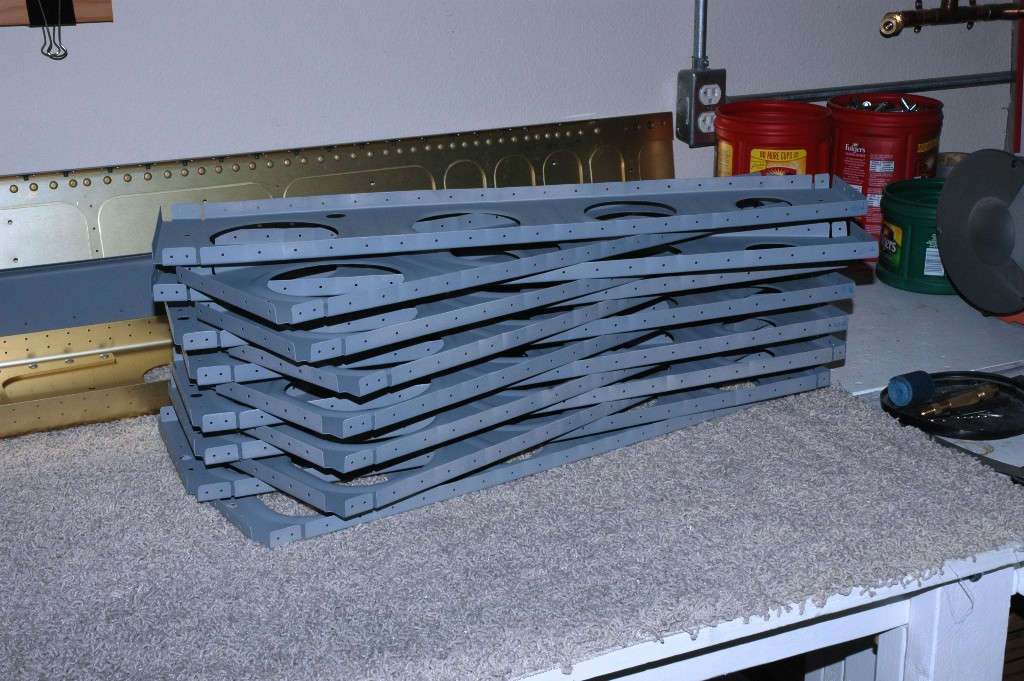
And tonight, Monday, I primed the left (or was it right?) ribs, to be carefully stacked in the a.m. to await some riveting. And than, folks, is where I sit right now.

My next step, which I hope will occur next weekend, is to rivet the main ribs to the main spar and then the rear spar. Then, soon enough, they will be hung with care on my wing stand. We'll see whether or not my careful calculations and measurements will make for a level wing spar when mounted on the stand. On to riveting again. Haven't done a 470 rivet for awhile. Need to study some of those "good" websites to make sure all my bases are covered.
May 14, 2010
Okay, now it's been nearly two months since I updated, and nearly that long since I did anything. I've been helping rebuild my son's new house since mid-March, so the RV-8 has had to have been set aside for the time being. Between my job and our own house and other time demands, my spare time has been spent in Elverta, California. However, I have had a bit of time here and there, but haven't posted anything here due to time constraints.
Basically, I finished riveting together the ribs and spars for the main structure for both wings and gotten that into my wing stands to await further work. Here are views of the wing stand being finished up. In mid-March my A&P buddy Greg was able to cut and drill some angle iron to finish out the wing stand. The original material I thought would work was too flimsy, thus the changeout.
And the completed stand ready for the wings.
Back to the riveting, setting the rivets to hold the ribs to the two spars was straightforward with a few stunning exceptions.
A bit closer...
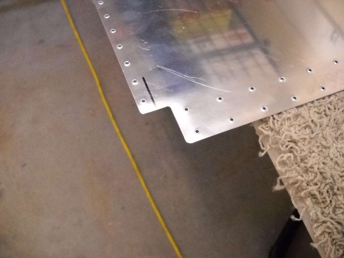
And a view of the front of the spar near the wing tie down structure.
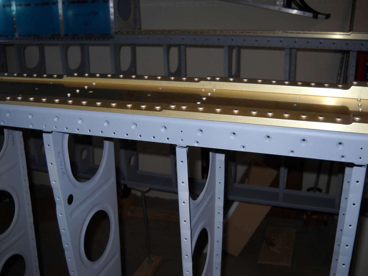
And here is the right wing coming together with the rear spar awaiting rivets.

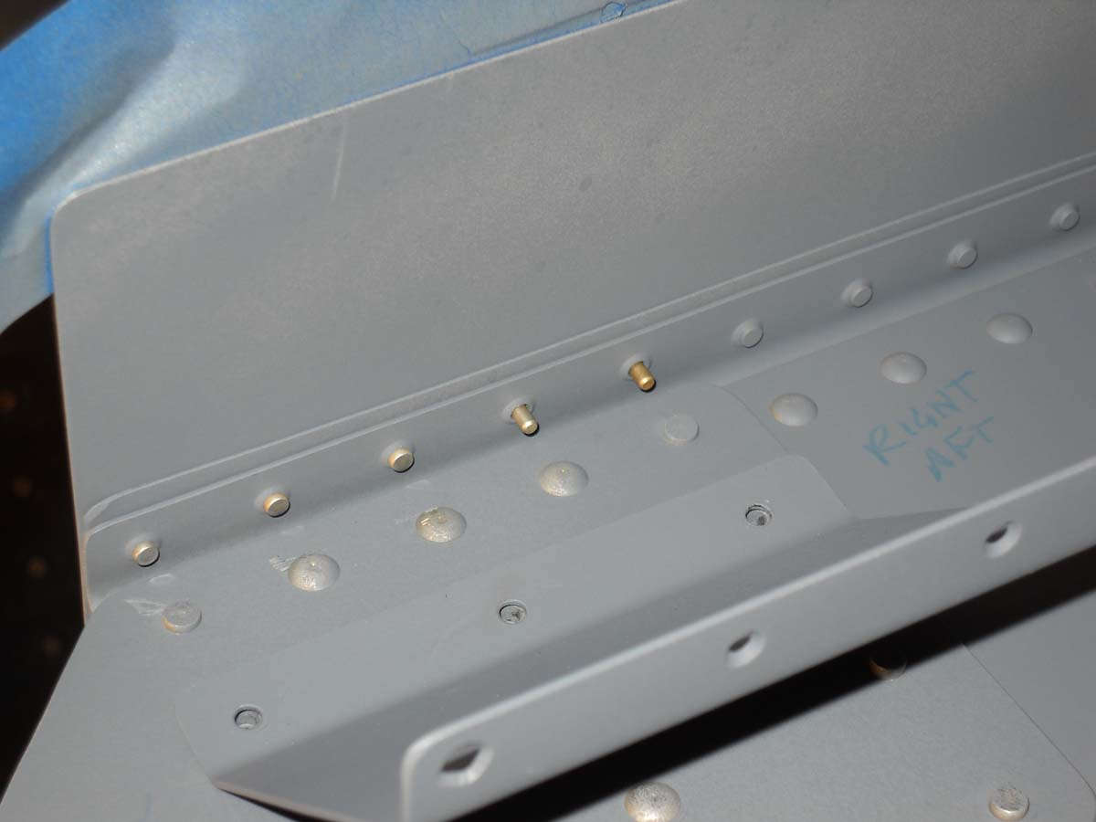
Here the rivets are almost done. It pays to pay attention to the plans here, as there are several rivets that are not driven in this process. They await later structure.

Because if you don't pay attention and you have to drill a rivet out, this is what it looks like for these rivets, at least for me. Ugly. You can't easily get at the manufacturer's head of the rivet for drilling so you have to come in from the shop head side. I salvaged this hole post-rivet and it turned out okay but right here it looks downright, yep, ugly.
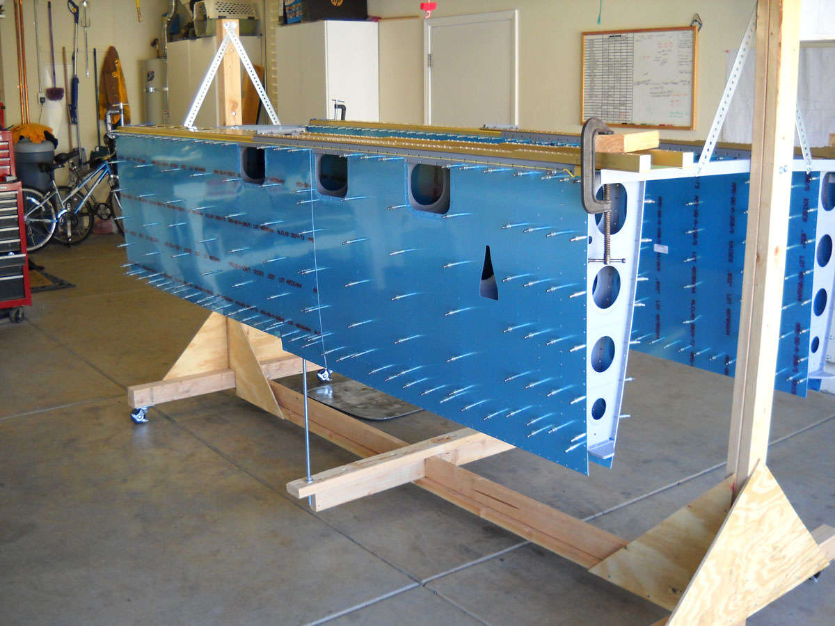
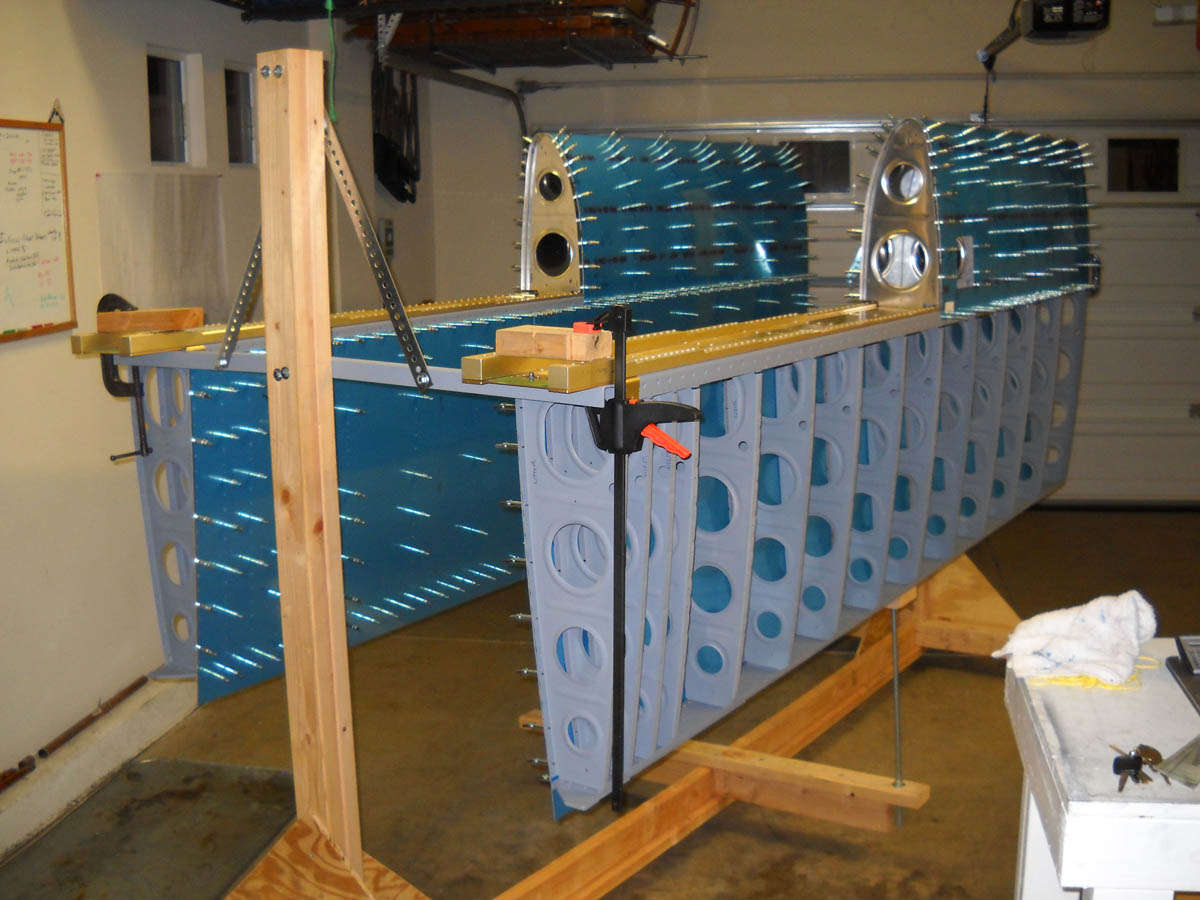
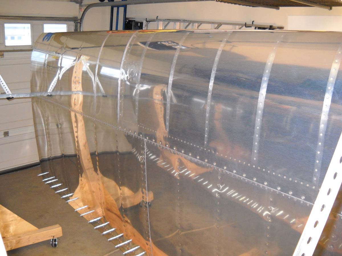
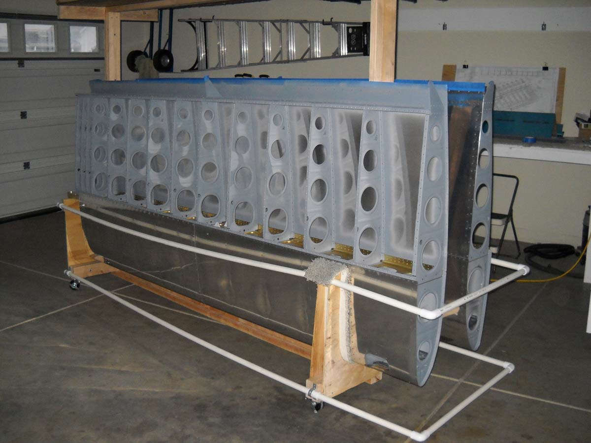
I knew a long break in my work was coming so I wanted to get the wings into the stand before that happened, and organize a few things and clean the shop, er, garage up a bit. Here are the wings in the completed stand.
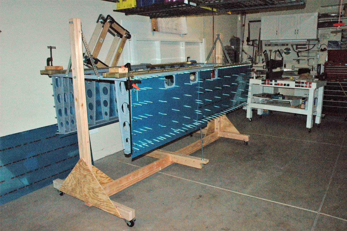
It seems to me a lot of guys really get carried away with making sure everything is perfectly rigid and perfectly straight. To me, though, the point is to straighten the wing so the skin pre-drilled holes align with the spar pre-drilled holes. That is, after all, what the plans say. So, this taut string makes sure things are straight.
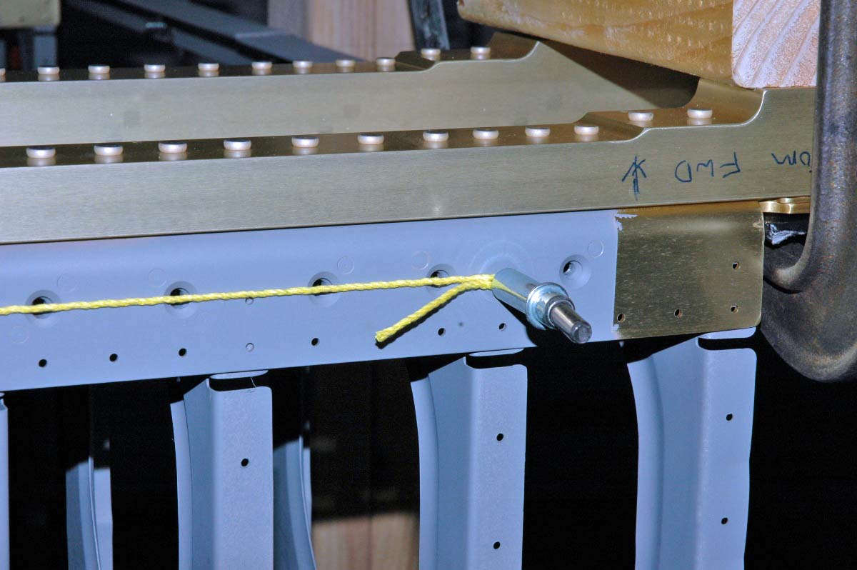
And this is my leveling gizmo...some threaded rods, a few nuts and washers, and a two-by-four. I want to be able to move this stand around, so this makes it portable to me. Once the skin is on and match drilled it becomes less important to have this perfectly straight, at least until you are ready to rivet.

So, here is where I am right now as I get ready to slowly get back into putting this wing together. It's been a bit frustrating not being able to work on the airplane, but there is a time for everything. Now I think it's about time for the wings again.

September 12, 2010
Whoa, baby, four months since I've done any substantial work on the RV-8. Too long, but other things demanded my time and that's the way it is. But, I think some of the other things have been taken care of, at least somewhat, so I expect to spend the fall putting these wings together. So, this weekend I did get about five hours in on the construction. It was nice to dive back in.
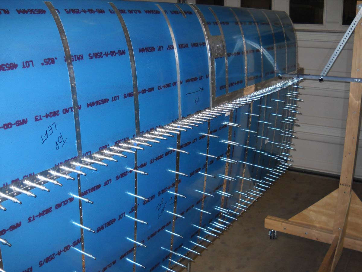
In summary, I finished match drilling the upper wing skins to the wing structure and then assembled the right outer wing leading edge.
Many weeks ago I was able to match drill the lower surface of each wing. So, I had the two upper surfaces to complete.
It probably takes about ninety minutes to match drill all the holes on a wing surface. Every third hole has a cleco, so once you go through the wing once, all the clecoes are moved to exposed the undrilled holes, then you get those holes. Not much too it, but I did find I had to be careful on the aft (bottom) line of holes near the inboard end of the wing since there is a spar doubler on the aft spar just waiting to get nicked by the drill. Drill shallow and straight on those ones especially.
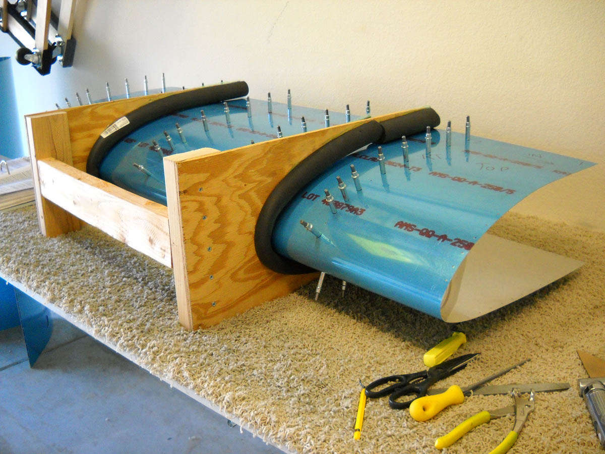
I built the leading edge stand a few weeks ago during some spare time. Some scrap plywood and a two by four, then some pipe insulation and there you go. The plans said not to spend too much time on it since it only holds the skin while you fit the ribs into place. So I didn't. Worked just fine.
Had to do the prep work on the ribs. Some guys recommend doing all the wing, leading edge, and tank ribs all at once. Get it over with. I broke it up a bit and left the leading edge and tank ribs for now. Spent an hour on the right wing ribs and got them ready. Fitted them into place pretty easily, then clecoed the whole assembly together.

It is then just a matter of picking it up and fitting it into position on the outboard leading edge. The plans have you remove the lower wing skins before you test fit this. It becomes apparent quickly why this is done as the clecoes holding the outboard rib in the aft wing section also hold the rib flange on the leading edge section. To get to the rib flanges the skin has to come off. But, even resting in position it looks pretty good to me.
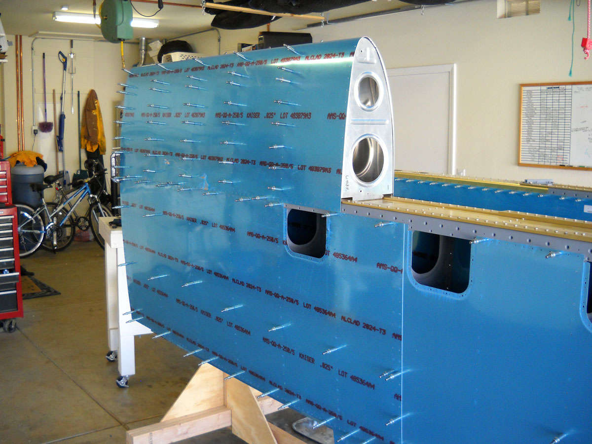
Another view from a different direction.
So, next up: do the same for the left wing leading edge, and then do the fuel tank preparation work. More ribs, more fluting, more poring over the plans to figure out what I'm doing. But, in a few weeks I expect to have the aroma of Pro-Seal filling my garage.
September 19, 2010
I made some good progress this past Saturday. Spent the better part of the day working on the two outer leading edge wing sections. At the end of the day, all the parts were fitted and match drilled. Good to go. On to the fuel tanks.
So, I started with rib prep for the left outer wing leading edge. Same drill as last week...edge finishing, flange squaring, and fluting. All the ribs took about an hour plus. Spent a bit more time on the leading edges of the leading edge ribs. Wasn't real happy about how some of the ribs fit into the right section last week. Some of the flanges don't line up real well so the curving of the front has some higher edges than the others.
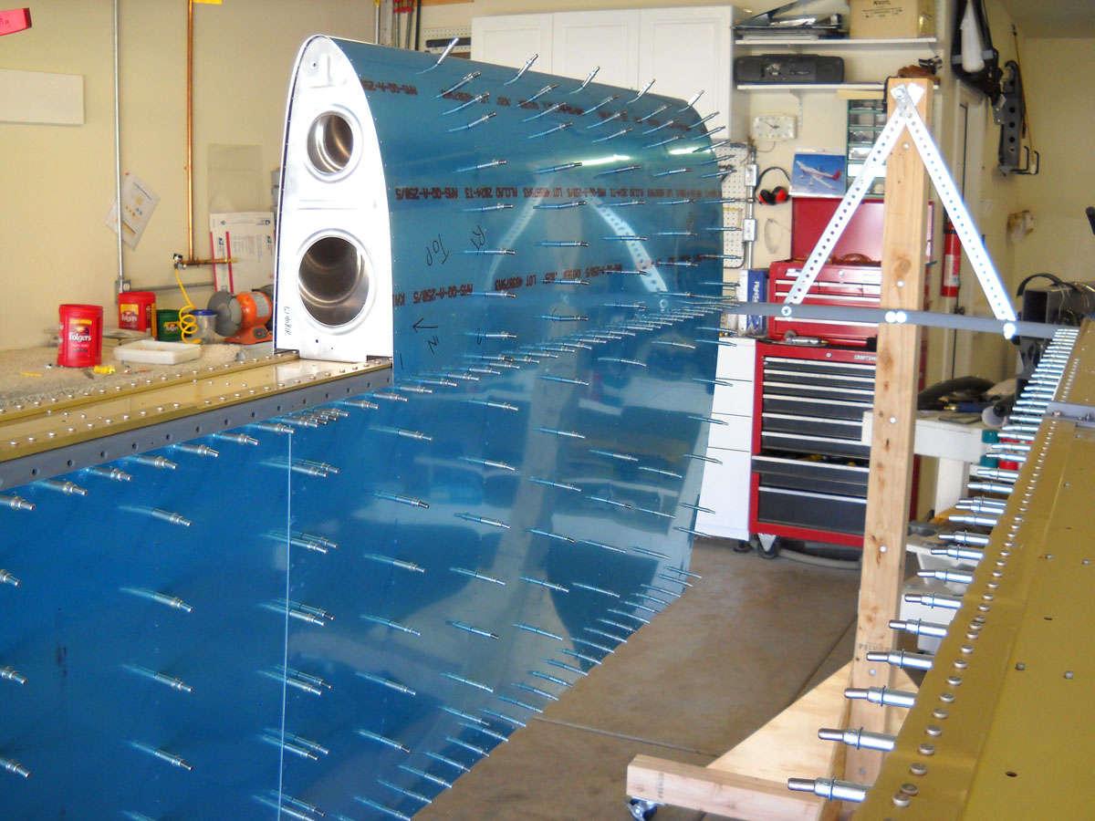
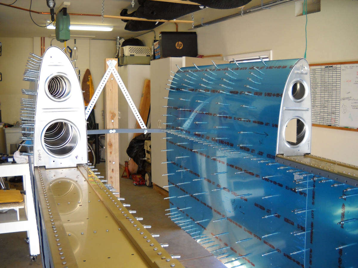
After the ribs were finished, I fit the skin and the ribs together in my little stand. Inserted the clecoes in every third hole or so.
So when that was put together, the leading edge assembly was fitted onto the wing spar. Note that by this time I had removed the bottom skin from the wing section. This allows access to the spar flanges so clecoes can be inserted to hold the leading edge to the spar.
So, here are the two wings with the outboard leading edges fit into position.
I then took off the right leading edge section to rework a couple of the ribs I wasn't happy with. Before I rivet this stuff together I'll go over each part at least once more.
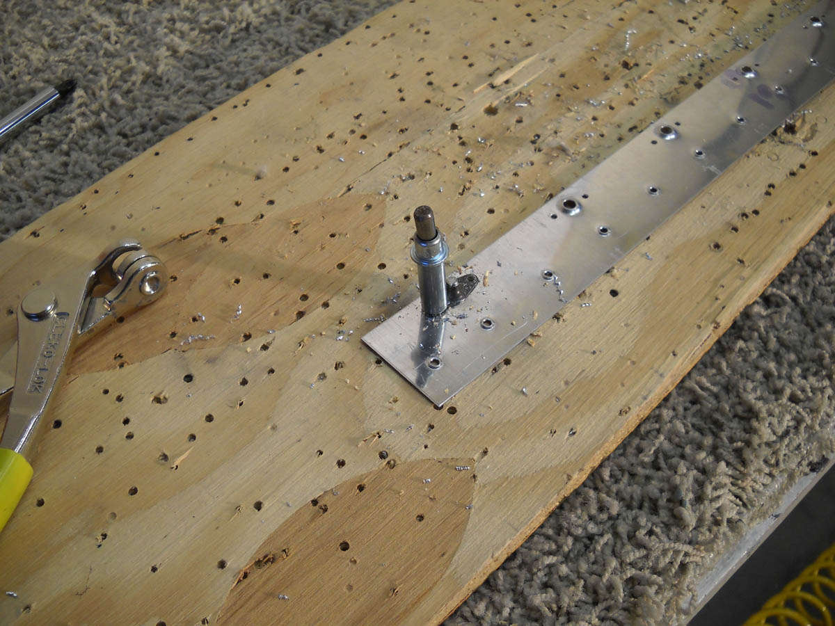
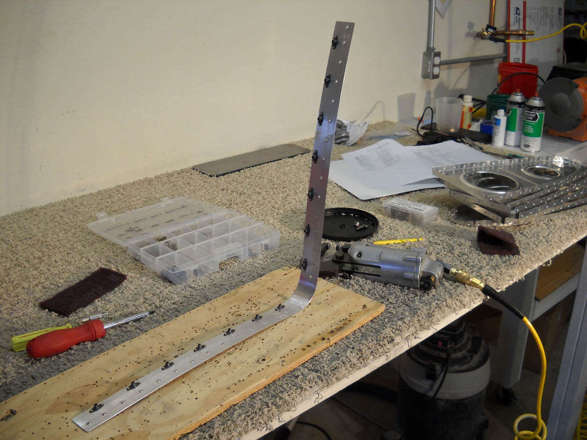
The next step is to fabricate two metal strips that are used to mount nutplates that are then used to help hold the fuel tanks in position. They underlay the joint between the outer leading edge section and the inner fuel tank leading edge section. The aluminum strips are fit between the rib and the skin and riveted into position there. Here is the first strip being fitted.
Once the strips are carefully positioned they are matchdrilled from the skin through the strips and through the undrilled rib flanges. Add clecoes and step back. Cool.

Then, the process of match drilling all the skin to rib hole began. Pretty straight forward if a bit boring. More holes than it looks. Need to be careful here as there are some ribs that attach from the aft section that are double riveted to the spar through the two skin sections. One needs to make sure the aft hole has a cleco before drilling the forward hole through the skin. It makes more sense if you see it.
So, as the day wrapped up, all the holes were drilled and the outer leading edge sections are done up to where everything is disassembled for dimpling and final preparations.
However, that comes later after the fuel tanks are built. And, that's the next step so perhaps next weekend I'll be able to move forward on that.
December 27, 2010
Jump forward three months and two weeks....
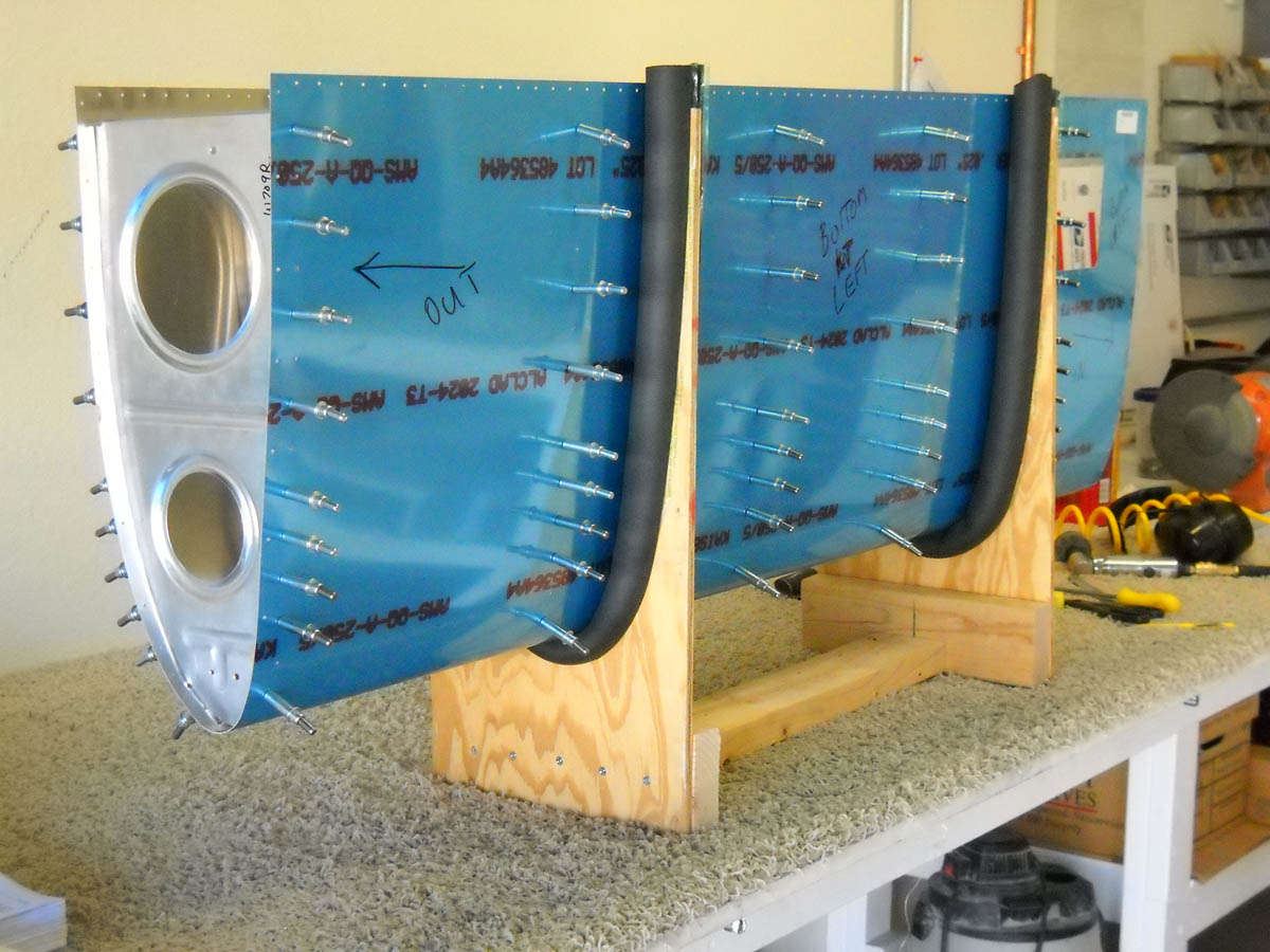
So, with the fuel tanks completed, it was time to get back to the leading edge sections. Here is the right leading edge back in the cradle getting disassembled for preparatory work.
Starting with the right leading edge section, all the skin rivet holes were deburred and dimpled, the ones on the edge with a squeezer and the interior ones with the DRDT-2. After that, I did the edge finishing and roughed up the interior for a light coat of primer.
I also did the prep work on each of the ribs, consisting of deburring and then dimpling. I then set about to drill and rivet the nut plates on the leading edge to fuel tank joint plate.
Here is the joint plate in the midst of having the nut plates riveted into position.
Finally, I measured and riveted, using pulled rivets, the nut plates that will be used to accept the Duckworks landing light reflector that will go in each of the outboard bays on the leading edge sections.
So, with all that complete, I carefully cleaned the ribs with hot water and soap, and wiped the interior of the skin down with MEK. They were then set aside to dry for a day or two, and then I did a light spray of self-etching prime on the ribs and mating surfaces on the wing skin. Let that set up for a few days. Yesterday (Sunday) I took a few minutes and clecoed the right leading edge together. It is now ready for riveting.

Now, do all the above on the left leading edge section, and then we will rivet them all together.
First update in two weeks, but I was able to do a fair amount over two sessions in that time. I completed the right leading edge section and it turned out pretty well.
And another closer view of the completed part. This view shows the inboard splice plate where it will join to the fuel tank.

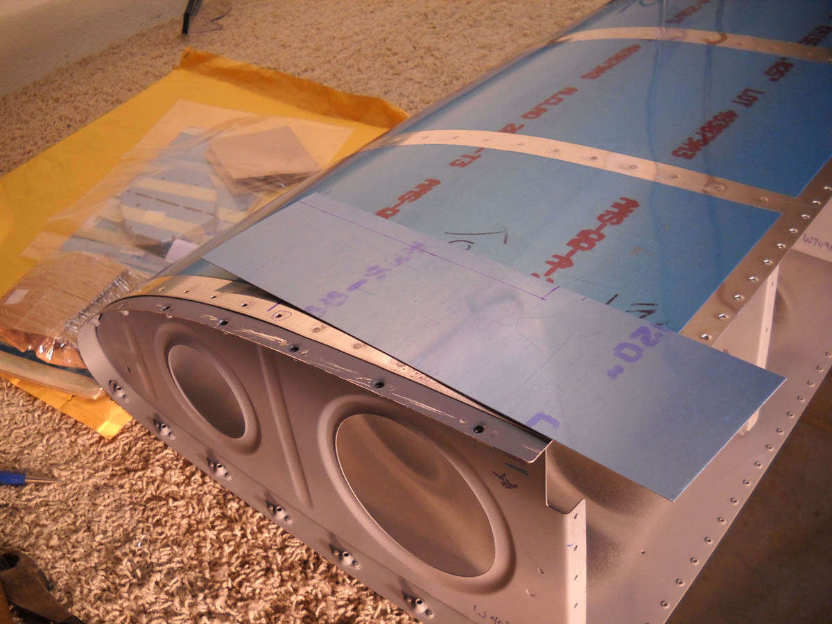
Speaking of fuel tanks, I jumped out on New Year's Day and figured I would test fit the completed leading edge with the fuel tank mounted on the wing spar. I was a bit disappointed with some minor "pillowing" that occurred between some of the forward screw holes on the forward, most curved section of the leading edge. Nothing unusual here, from looking at other web sites, but still something I hoped I could avoid. I spent the whole morning trying to get it to fit better, and ended up making a shim that was installed through the curve. It helped a bit, but not as much as I had hoped. More later, but here is a photo of the shim being measured and cut.
And, along the way, I continued the spar prep by countersinking all the holes for the leading edge and top skins. There are a lot of holes.

One of my son's, Nathan, has developed a latent interest in helping and I am happy to have him dive in with me. Put him to work deburring and dimpling all the wing ribs. He seems to enjoy himself working on this project and I think he will be joining me on Saturdays...my official workday. I would expect my other two sons to come by once in a while but they live further away and it's not as easy for them to find free weekends. Still, it looks like some hands will be helping. I still plan on having my wife drive at least a few rivets so she can later say, after the high-flying fruits of our labor are done, that "she helped."
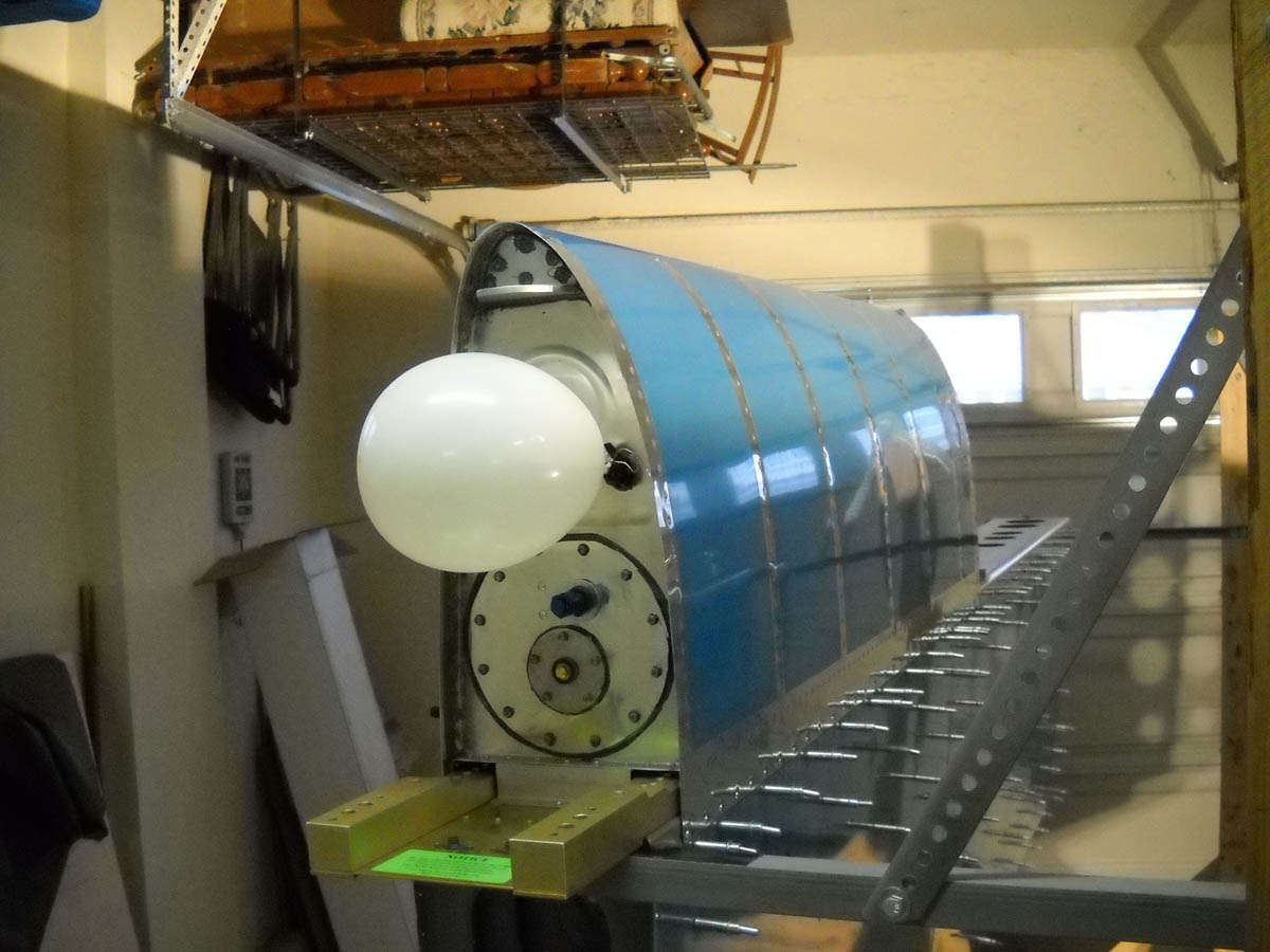
Ah, the fuel tank test. Not sure this is how Boeing does it, but it seems to work. What one needs to remember is that the balloon is not a leak indicator but a pressure relief valve. The point is to pressurize that tank to allow a check for leaks, but not to literally blow the tank up with too much pressure. The balloon works, thank you very much. Unfortunately, during my check, I did find one small leak where baffle and skin come together. More on that later, when I try and fix it with minimal tank invasion (MTI). The other tank seems to be okay.
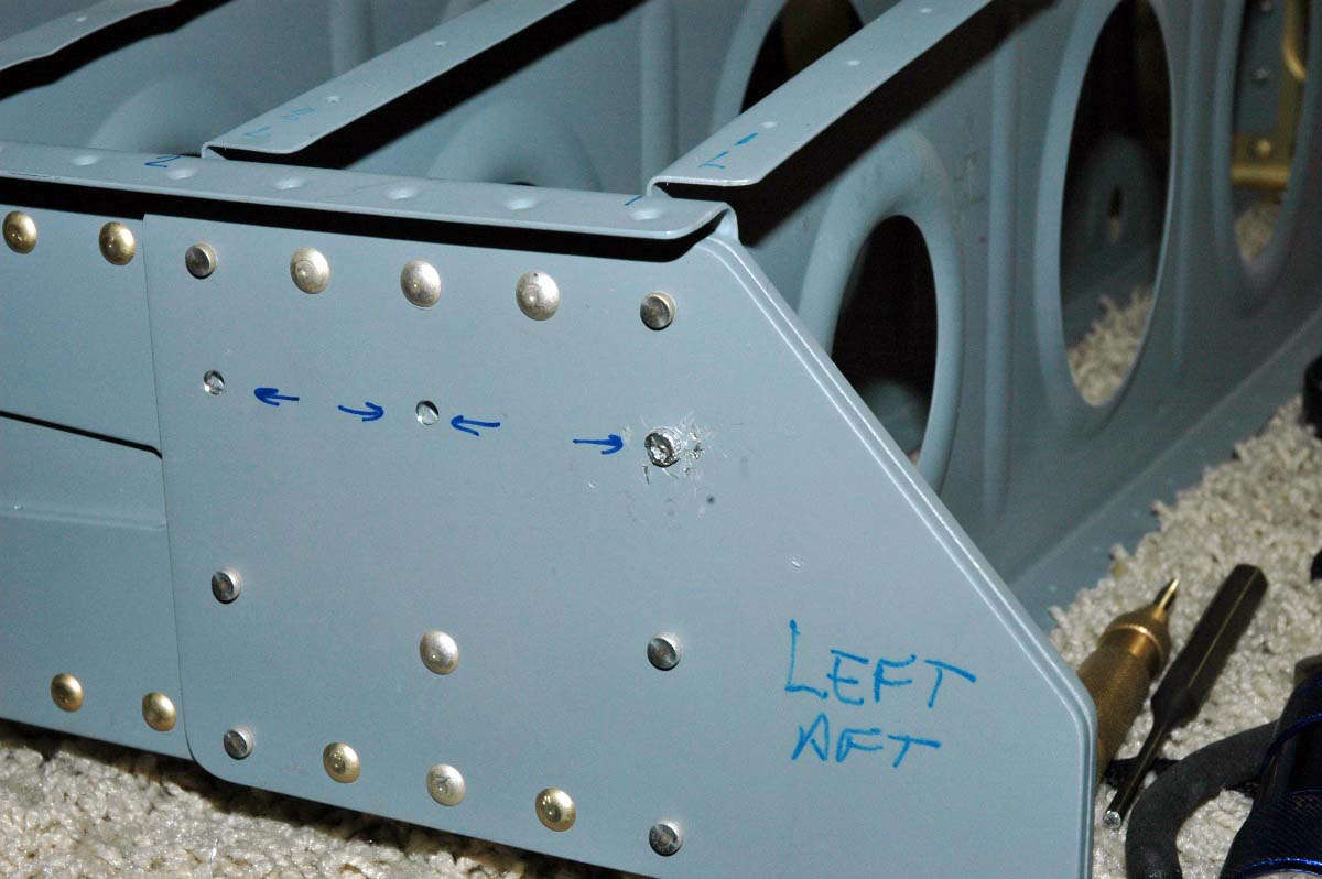
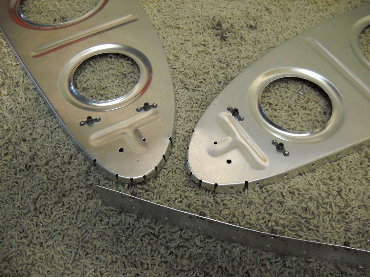
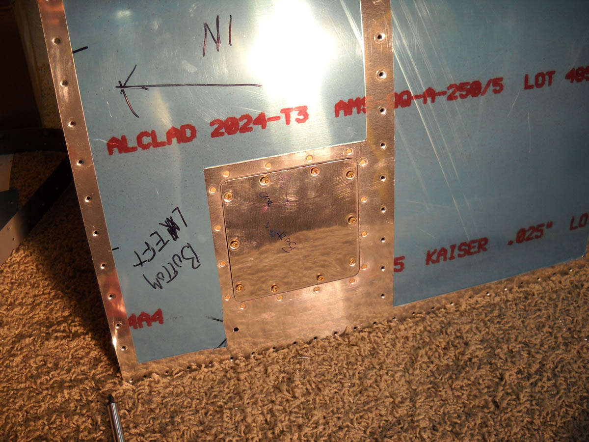
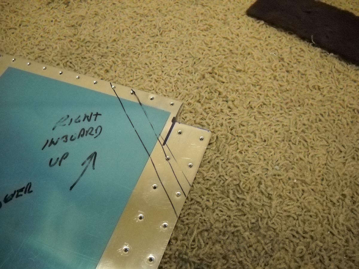
The new RV-8 wing kits come with a stall warning system for installation in the inboard bay of the left leading edge. The opening in the bottom of the wing is for post-construction access to the system. I'm planning to use a Dynon angle-of-attack indication for my stall warning, so I'm not installing the Van's stall warning. Still need to address the openings, so I riveted the not-to-be-used holes and put together the nut plates, reinforcing plate, and access cover for the bottom wing.
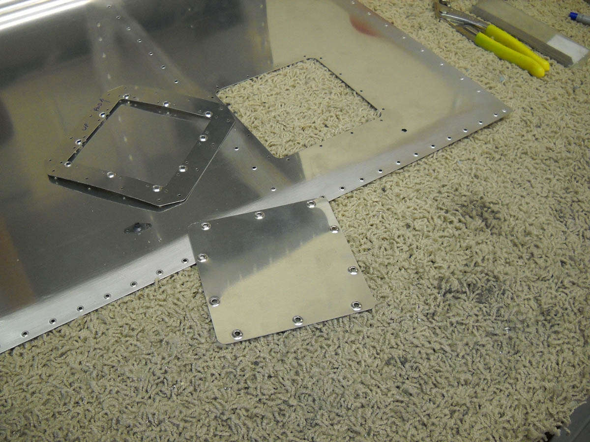
Here's how it looks nearly done on the bottom of the wing.
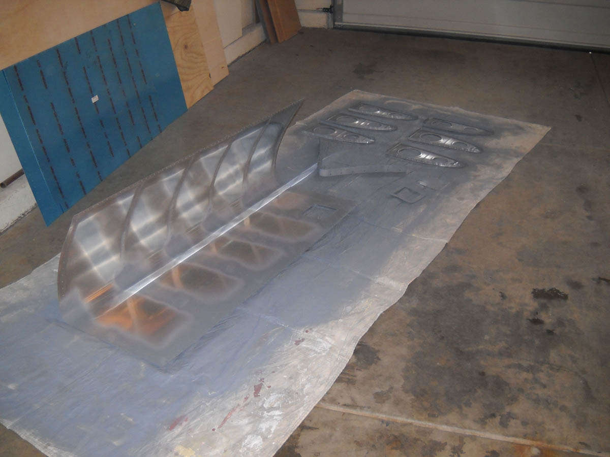
Not many photos to show for it, but I basically prepped and primed the left wing leading edge like I did the right leading edge. The paint shop, to wit:
And, then start the process of riveting the left leading edge assembly together, which is what is going on here.

So, I am getting closer to doing the final wing assembly, and then to rivet the top skins on. Stand by....
Not exactly rocketing along is how we'll call this process. There's been a lot going on over the past two weeks so I've not been able to spend as much time as I've wanted to on the project. However, I did get one good session Saturday before last. Most of my accomplishments in this period have been to prepare the wing leading edges for riveting to the main spars.
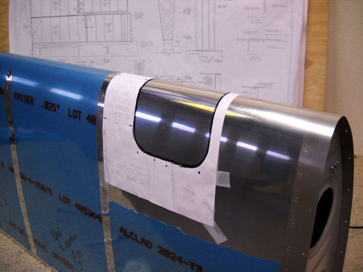
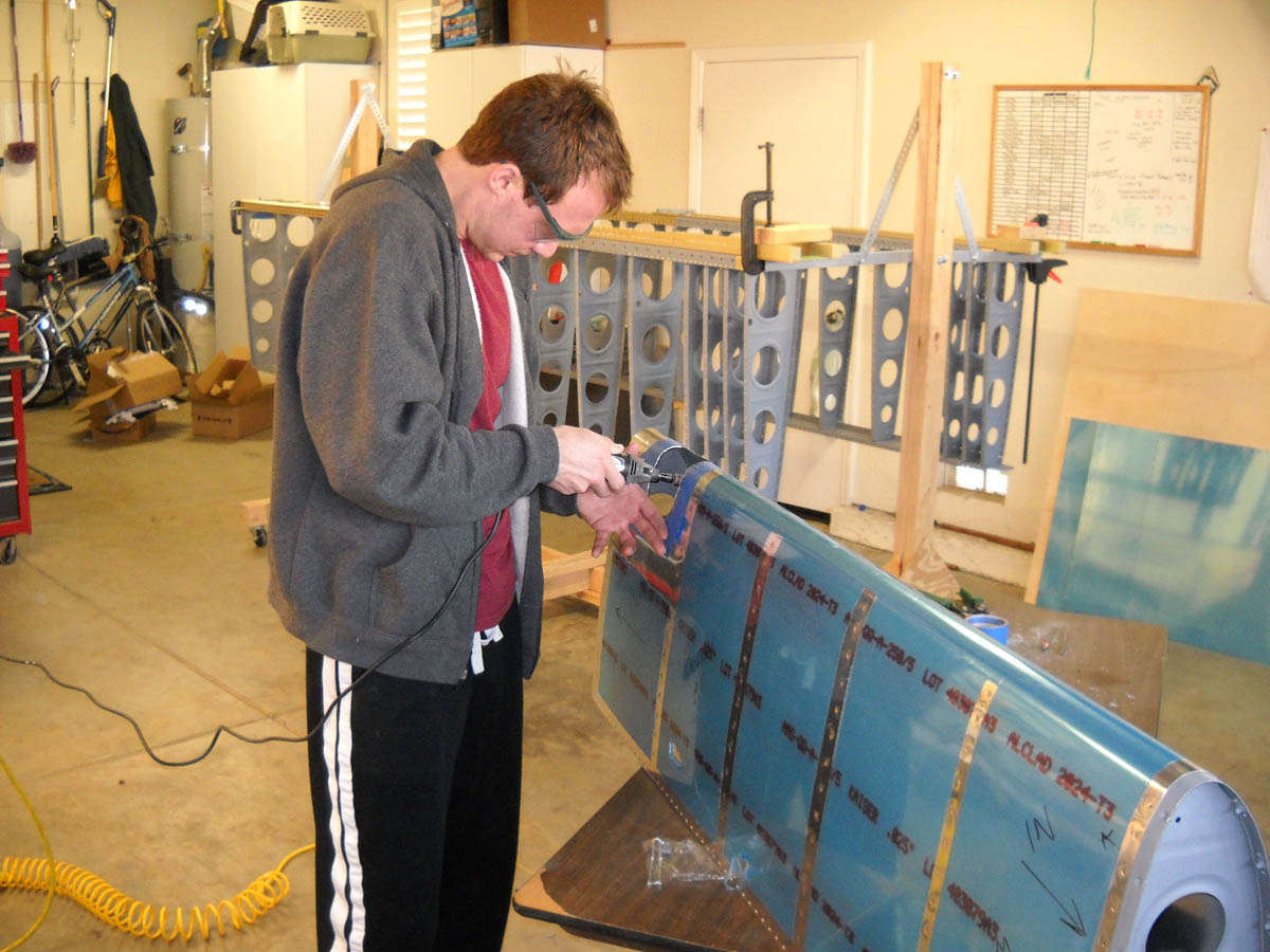
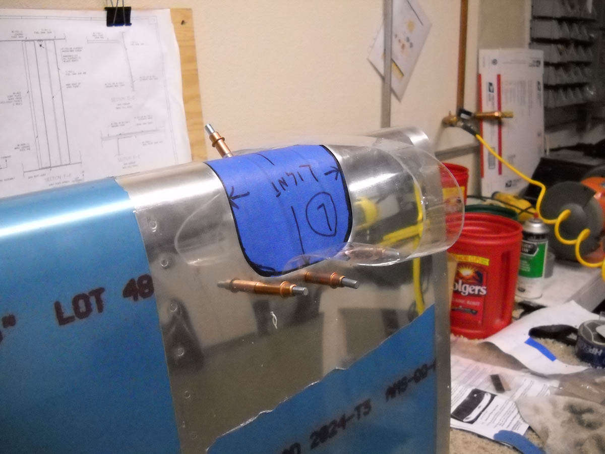
Among the major tasks was to install the landing lights into each of the leading edges. I'm a Duckwork guy myself, and have the boring old (non-HID) lights. Cost was part of that factor, but this is not planned to be a big night time operation, so I don't want to get carried away. The first step is to cut out the template and tape it to the leading edge to place the cutout properly
Once the layout is checked and double checked, the leading edge is cut away. I had purchased a pneumatic metal saw at Harbor Freight based on what I had read on some other sites. Not particularly happy with how it worked. Ended up using my unibit to drill some holes, then snipped out the areas between them. Here is my son Nathan working with a Dremel with a sanding attachment doing some finishing work on the first wing. Nathan has become a regular Saturday helper and the helping hands are welcomed. Makes things go quicker, and a bit of good company to boot.
When Nathan wasn't working on the leading edge, he did some finishing work on the four wing top skin sections. The each have to be deburred, edge finished, and dimpled. Here is the first section getting dimpled.
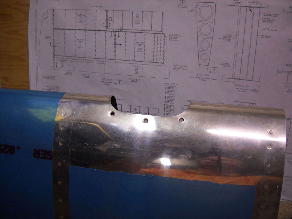
Back to the leading edge, here is the second leading edge section as I was getting a bit ahead of the learning curve. Used the unibit to drill these holes, then cut the area out. More holes closer to the desired finish line meant less snipping and less final shaping.
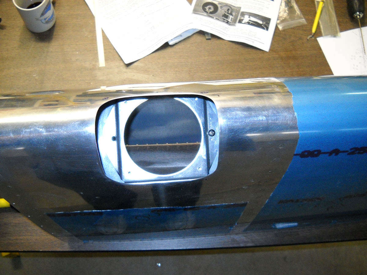
Here is the process in a test fitting stage with the mounting assembly fitted into the opening (from behind). Just to see how it all fits and figure out what the next step is.
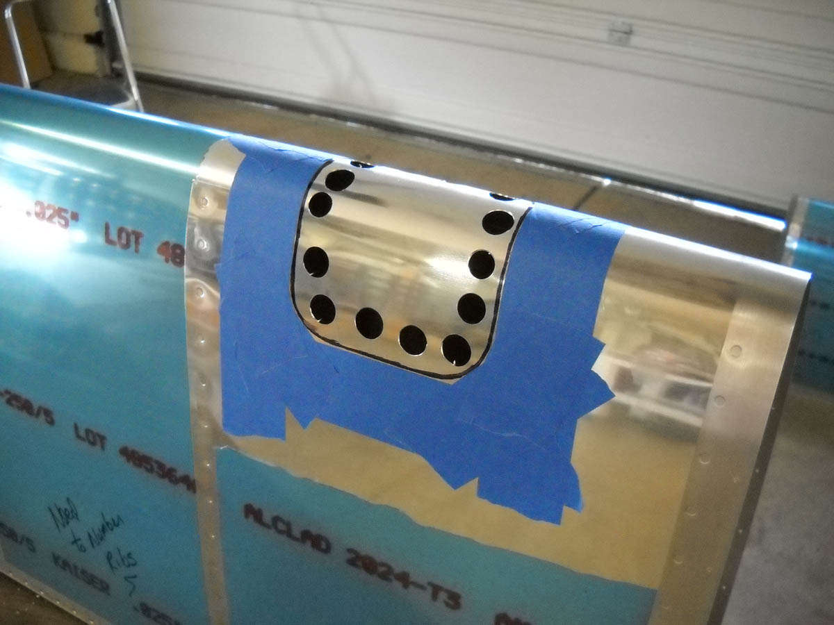
It turns out the next step was to protect the Plexiglas with masking tape and fit it into position. Three holes are drilled in the skin on each end of the opening to take the mounting screws (placed according to the template), and then those holes are used as drilling guides for the Plexiglass. A bit hard to see, but I also have the Duckwork suggested tape strap to pull the Plexiglas tightly to the skin for the drilling of the mounting holes. Clecos are in the three lower holes, already drilled.
Here are the three mounting holes on one of the leading edges finished and dimpled.
I didn't take any photos, but there are two mounting strips that accept the nutplates, one for each end of the glass to match up with the skin and Plexiglas holes. Those metal strips are taped with foam tape to the Plexiglas to hold them in position. The screws then go through the skin, the Plexiglas, the strips, to the nutplates mounted on the strips.
Once assembled and finished, it looks a bit like this:
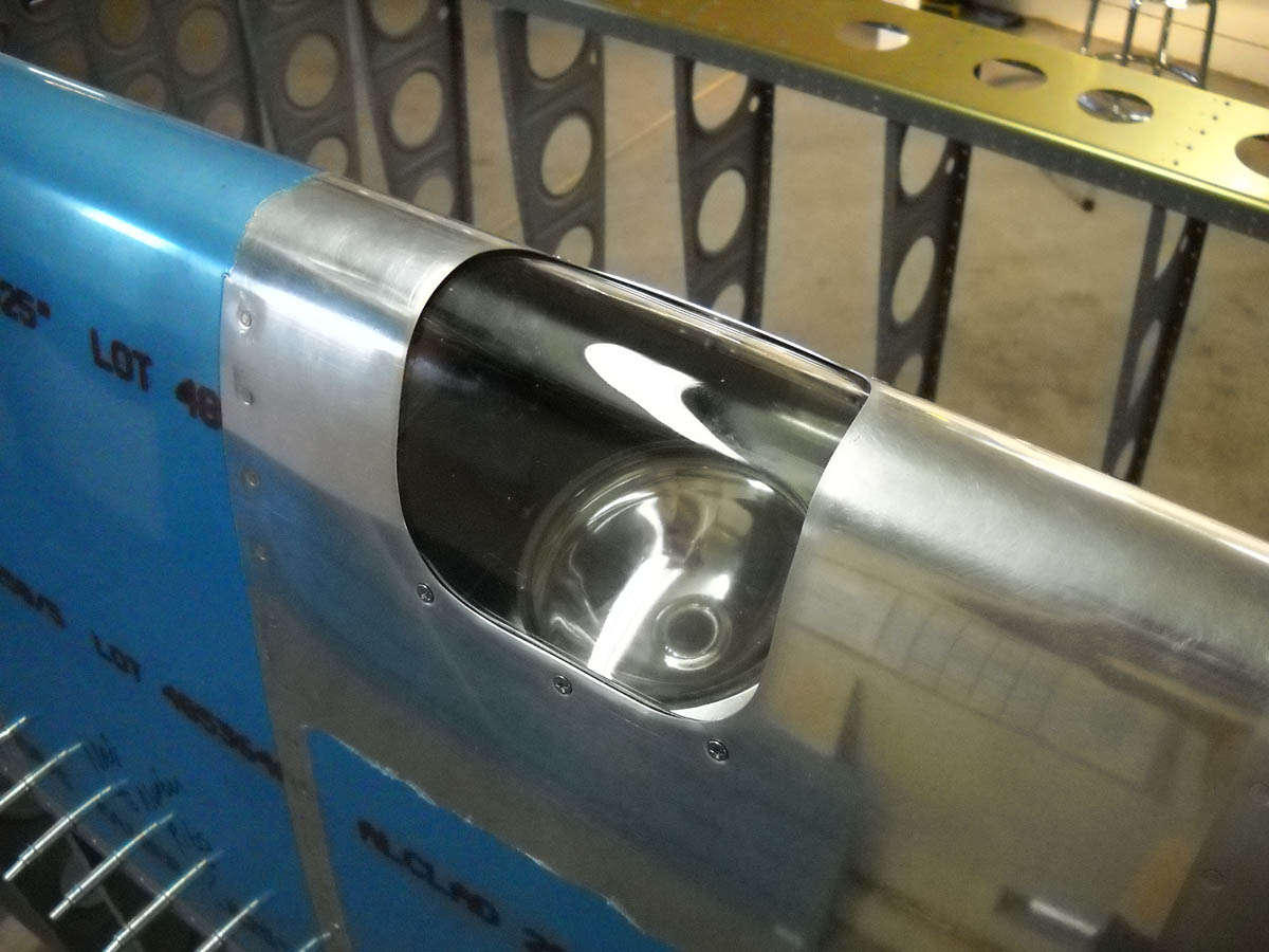
This one turned out pretty good. Not quite as happy with the other one. The Plexiglas doesn't fit as tightly to the skin. A bit more work might be in order.
However, the two light installations were our main accomplishment over the past two weeks. I installed the glass reflector but left the bulbs out for later installation. Those will go in after the riveting on the leading edge is done, probably at the same time I wire the wing.
The other work was in finishing up the main spar with a bit of primer, plus an overall clean up and inspection prior to attaching the leading edges. Also, work continues on the upper wing panels to get them ready for riveting. As for this past weekend, we only a hour or two to work, but we started the riveting process of the right leading edge. There are the six ribs that need to be attached to the spar and access to the inner four can be a bit challenging. We dipped our toe in the water and found it to be doable. Next weekend, we hope to, thus, do.
This photo is, obviously, of the left leading edge in position. Both are now clecoed on the main spar and work continues.

January 31, 2011
Got a good day in last Saturday but, of course, did not get as much done as I had hoped. We are close to having the top skins ready to be riveted on but this is not a quick process, especially with one day a week to work right now.
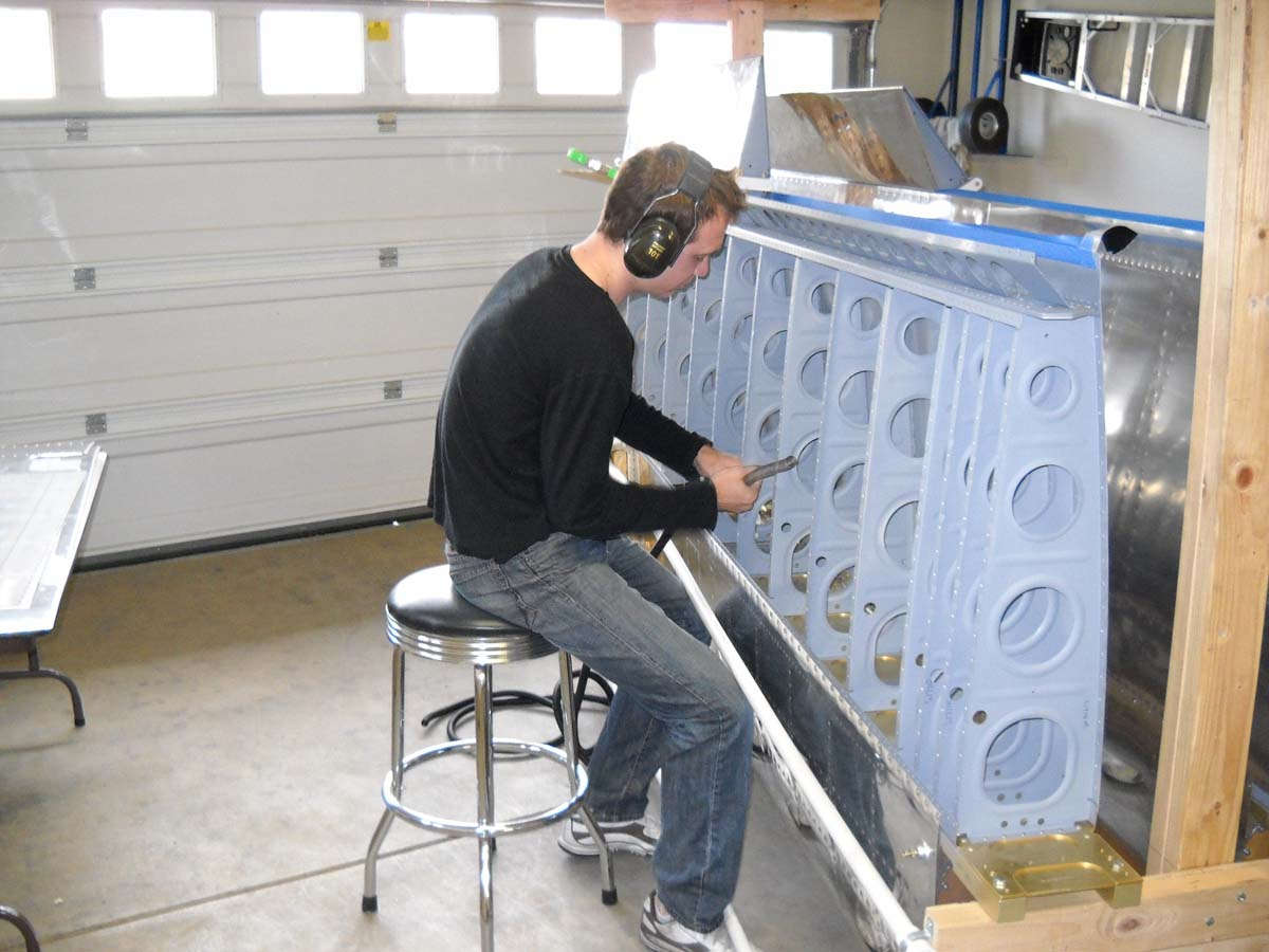
Nathan started the day deburring several of the skins, and then we dimpled them. Then, those were set aside and we went back to riveting the leading edges onto the spar. We resumed work on the right wing where we still had several interior ribs to attach. Here is Nathan with his arm deep in the bowel of the leading edge. Sounds messier than it was.

So, we finished attaching the ribs on right wing and got one of the interior ribs done on the left wing. The rivets are hard to set and the rivet call out was the AN 470 4-5 and, for the inner ribs, the 4-6. Those actually seemed too long for me after we drove a few and seemed to cause some problems. We dropped down a size on the last ones we drove, and it seemed to work okay...they met the specifications for size after we were done, with one little exception.
After we drove these rivets I was not particularly happy with how the left side of this flange looked, as it is obviously not flush with the spar. This is the third rib in from the outboard edge. The right side is not great, but I think the left side rivet will have to come out and I'll have to figure out a way to keep the flange flush when I redrive the rivet. Another little challenge. Makes it fun, I guess.

After Nathan left, I continued work on the upper wing skin preparation. I had to create the scarf joint where the inner and outer skins met the aft end of the fuel tank. The instructions want you to thin out a three inch area at the corner to decrease each of the skin thicknesses so they will lie flush when riveted, and thus match the aft end of the tank. One Van's Air Force poster used this method: cutting a notch out of the inner skin to allow the outer skin to lie down at the spar so it is an even joint between the fuel tank and skin. Sounds like a better solution to me, so that's what I did.
Here's the right inboard marked where I was going to do the material removal for the scarf joint. The corner, though, is where I cut the notch out...the width of the overlap with the outer skin and one inch back from the edge.
And then the other side. This should work okay, at least in the test fit.
Then, on to the paint shop. A good cleaning of the skin with denatured alcohol (what is this stuff....alcohol without nature things?) and then some rattle can primer on the joints and any skin scratches. Not too much primer. Works good; lasts a long time, etc.

So, that was Saturday then. Not shown here: Nathan came back Sunday and set the skin to spar flush rivets of the right leading edge, both top and bottom, with the pneumatic squeezer. I had other obligations but he spent an hour plus in the hangar...er, garage...no, it's a hangar...working those rivets. He's getting into this aircraft building thing.
Also, today, Monday, January 31, I ordered the fuselage kit. Price increase tomorrow. Every penny helps. We have the back seat rudder pedals, we have the ground adjustable rudder pedals (front seat), we have the electric aileron trim. Wait about eight to ten weeks for delivery of one big wooden box, then put it together. Okay, then.
Couple weeks since I updated mostly because I did not want to spend the time working on an update when I could be working on the airplane and/or be sick. Sick mostly, but a bit of work on the airplane.
So, some lessons learned these past weeks:
Lesson #1: when you fit the fuel tanks on, don't screw down the bolts until you have at least started to screw the tank into the joiner plate lest you have to take all the bolts out and then do it again.
Lesson #2: don't freak out when you see some extra holes in the spar that might need a rivet (but might not) and certainly don't take the fuel tank back off before you research it further, lest you have to take all the bolts out and then do it again.
Lesson #3: don't freak out when you happen to cleco the top skins on the wing, then decide to clamp a laser level onto the rear spar and measure to see if there is any wing twist and then freak out when you find there to be 3/8" of wing twist and only find out later that when you cleco on the bottom skins also that the 3/8" twist virtually disappears.
Okay, those lessons tell a bit about how I spent a good part of the time I spent on the airplane these past two weeks. Two steps forward...waste some time...then three steps backwards...and waste some more time.
After all was said and done, though, the top skins of one wing are riveted on, and the second wing is ready to go next weekend. I've looked at ailerons and decided I can do this too.
So, to start the process, I did another fuel tank pressure test in my fuel pressure testing facility. It is calibrated to maintain a constant temperature to help stabilize the pressure, though I can't do much with atmospheric pressure, which varied by 0.15 inches in the 24 hours of my test of the second tank.
In the end, I decided a small pressure change was negligible and that I have two good and tight tanks (I hope). Moving on....
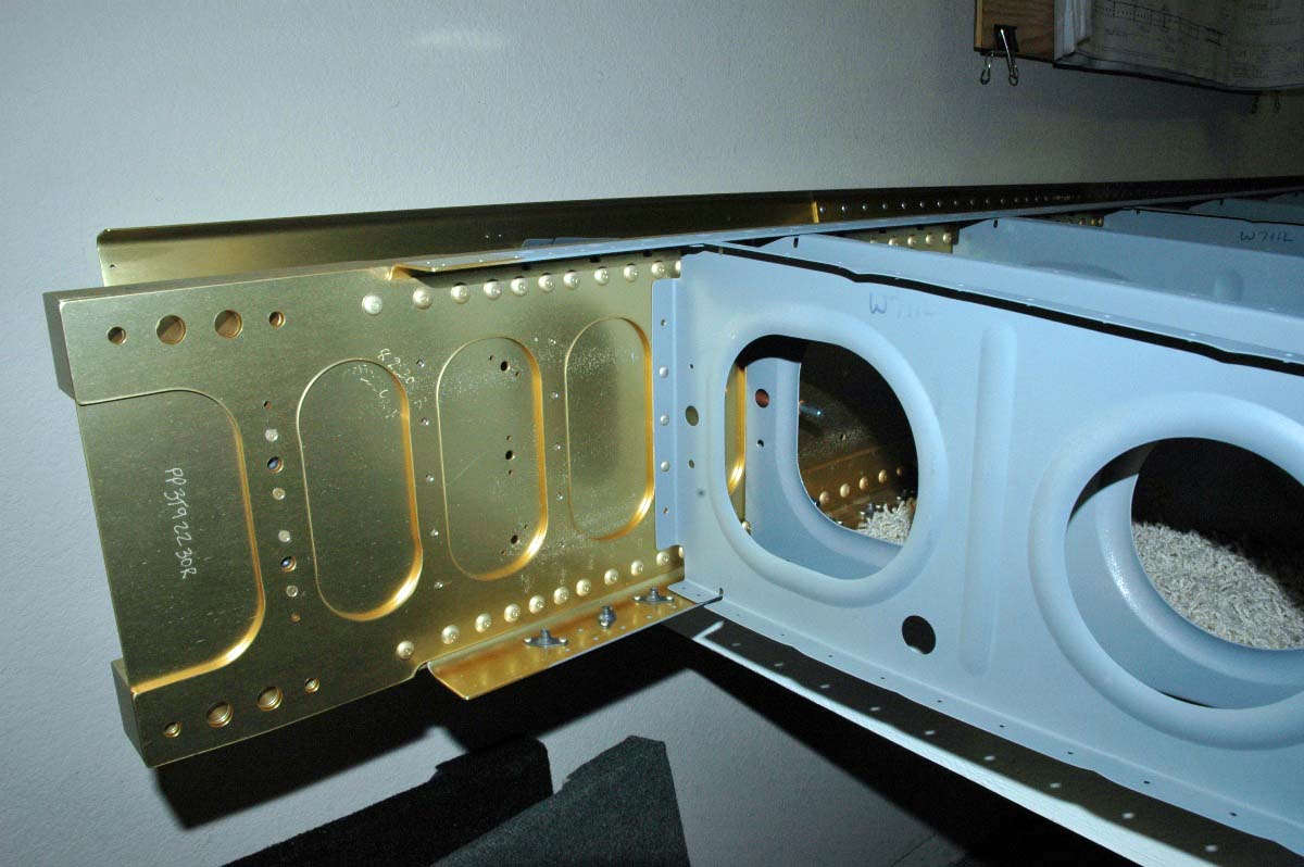
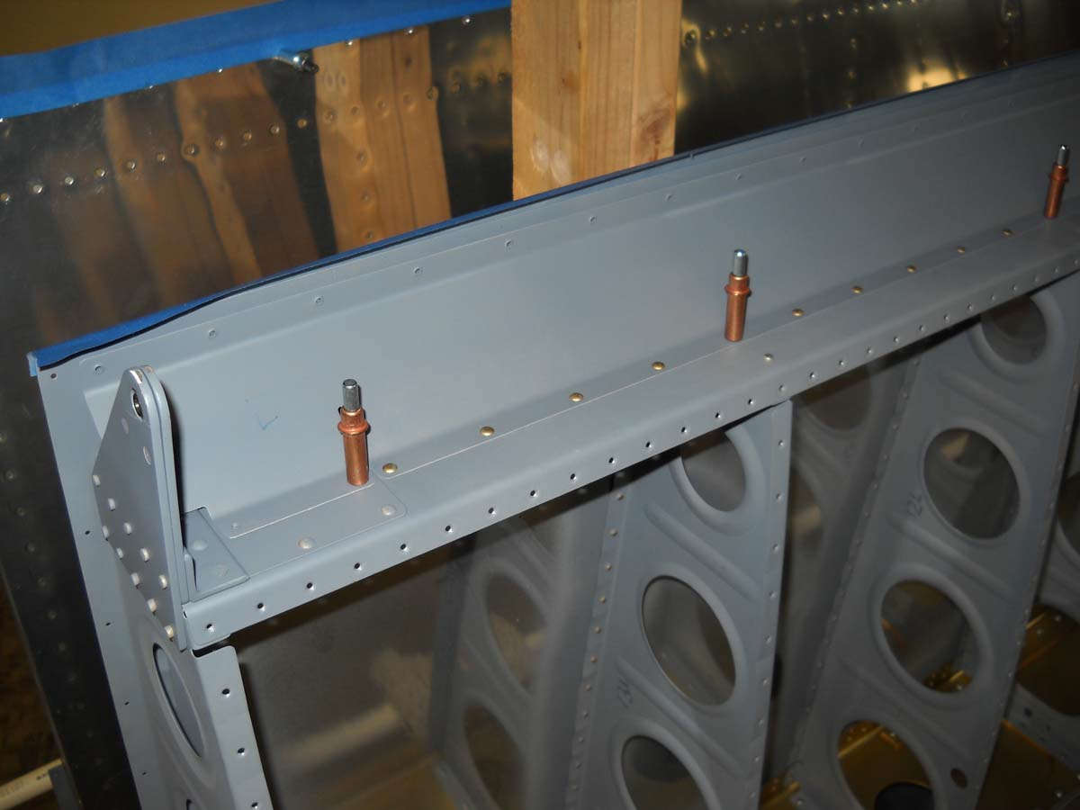
So, here is the left wing with the leading edge riveted on the fuel tank bolted and screwed on. As noted above, the tank went on and came off a couple of times. The fit between the leading edge and fuel tank was tight enough that it overlapped by a fraction of an inch after I bolted the tank to the spar, requiring me to remove the twenty-one bolts and realign the tank, insert some screws to hold it in position, redo the twenty-one bolts, and then install the rest of the screws. An after all that, I still have some pillowing on the top of the fuel tank, something I thought I had taken care of. More fine adjustments needed here.
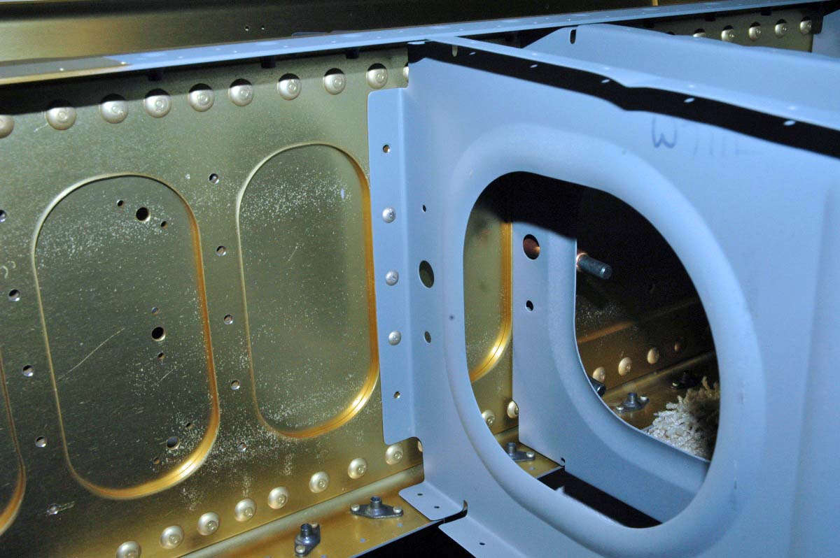
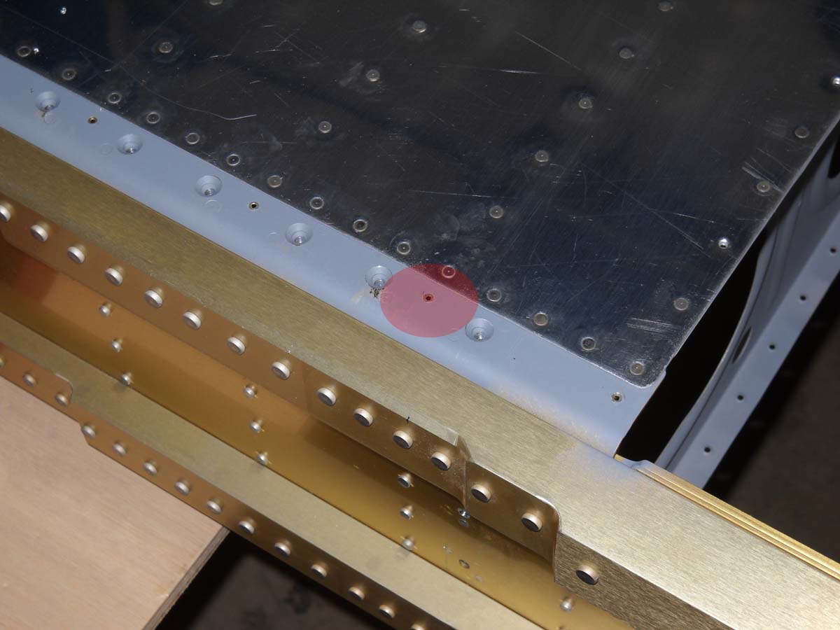
And, in the center of this photo, in the spar above where the rib joins the spar, you'll see the single little hole that is in the top line of larger holes set up for screws. I had seen this hole before and ignored it, because the instructions don't speak to it. When I was bolting the fuel tank on, I noticed the holes again and the corresponding holes in the ribs underneath. After much consternation, I researched and decided these holes are left empty. The instructions really don't address the holes. Much ado about nothing.
And here I am, smart guy, with my laser level clamped to the rear spar to see if there is any twist. There was. Eventually I was smart enough to add the bottom skins to the mixture and the twist is gone. Gone gone gone.
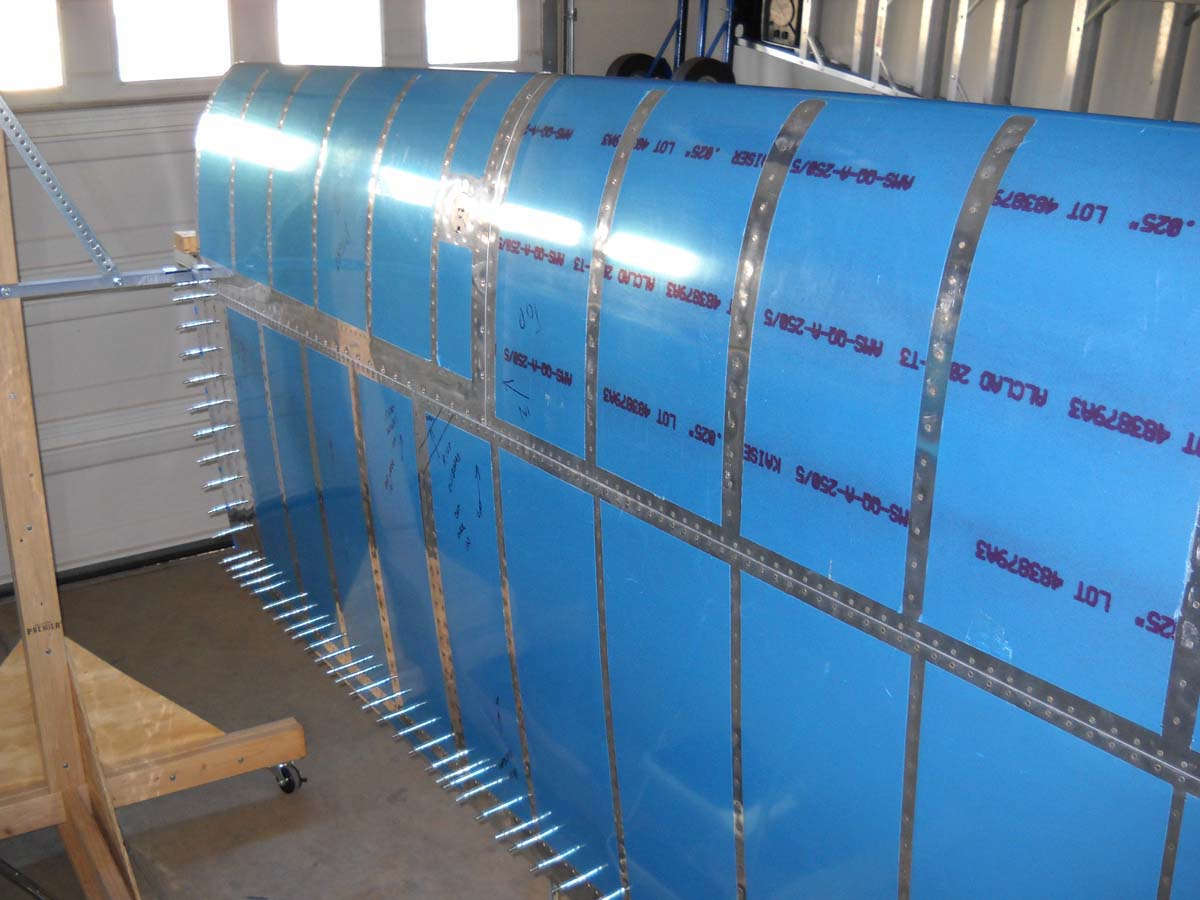
Okay, finally making some genuine progress, finally, with the top skins clecoed on the left wing.
Even more progress on this past Saturday when Nathan and I riveted the top skins on. Anti-climactic. All the prep work; then a bit of riveting.
Nice to see the finished product, though, eh?
February 27, 2011
Moving forward in the past two weeks...got the wing structure completed, rebuilt the wing stand into a wing caddy, and started the ailerons.
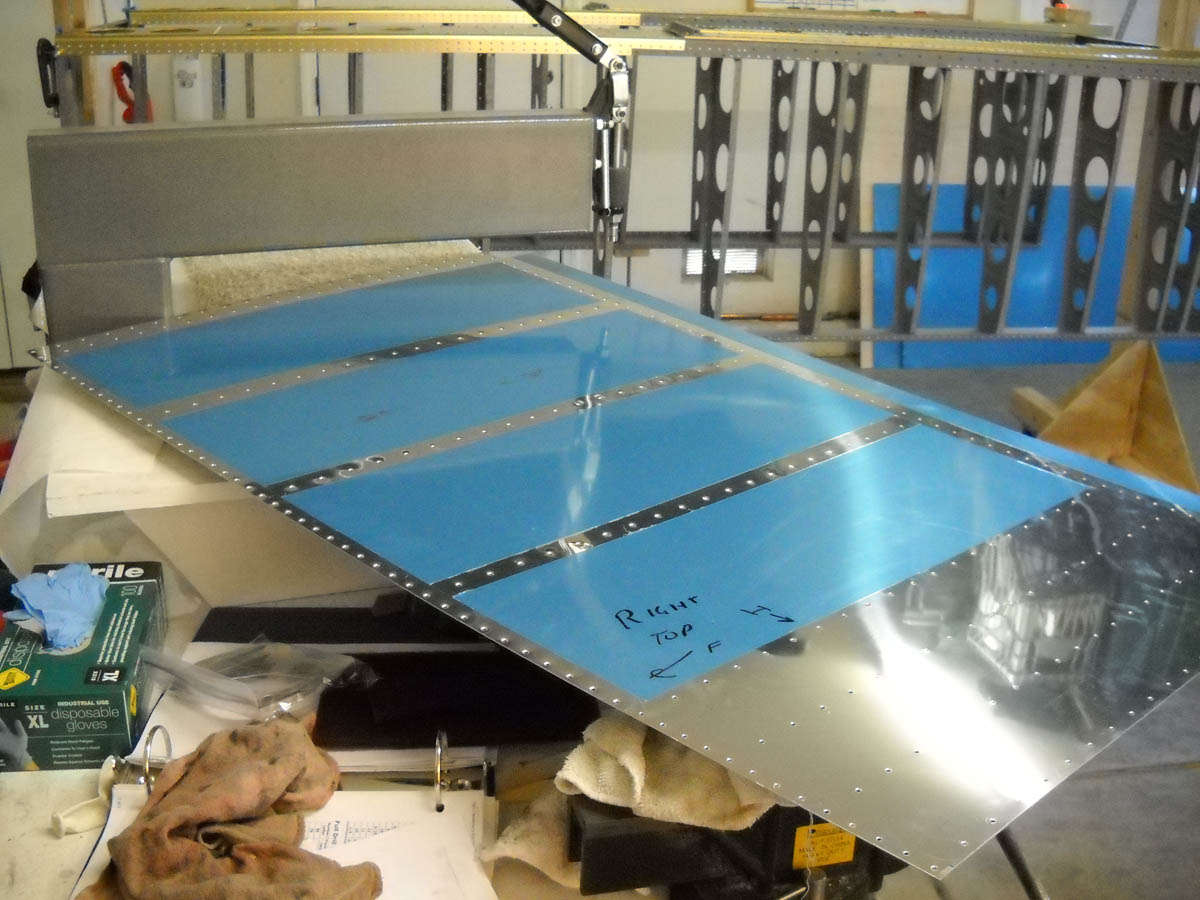
First off, Nathan and I completed the riveting of the upper skins on the left wing. Then, off comes the blue vinyl. Actually, I wanted to get the vinyl off because there was what seemed to be some cruddy stuff on some of the skins and I wanted to get it all cleaned off.
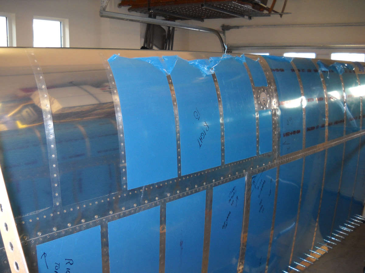
Naked skin. A milestone of sorts for me. Looks pretty good. A few flaws here and there, but I won't tell.
And the bottom of the naked skin wing.
So, I did one of those transformer numbers on the wing stand. I had originally built it to come back apart...nuts and bolts vs. nails...so that came in handy now. I wanted to shrink it down to make better use of room and turn it into a storage rack for the wings. Here is where I started.

And here it is, less wings. I added the overhead shelf to store flat skins and whatever else might go there. Not much vertical clearance, but it will handle a bunch of flat fuselage skins (if there are any) or, maybe, just the horizontal stabilzer and elevator. We'll see, but it gives a bit more room.
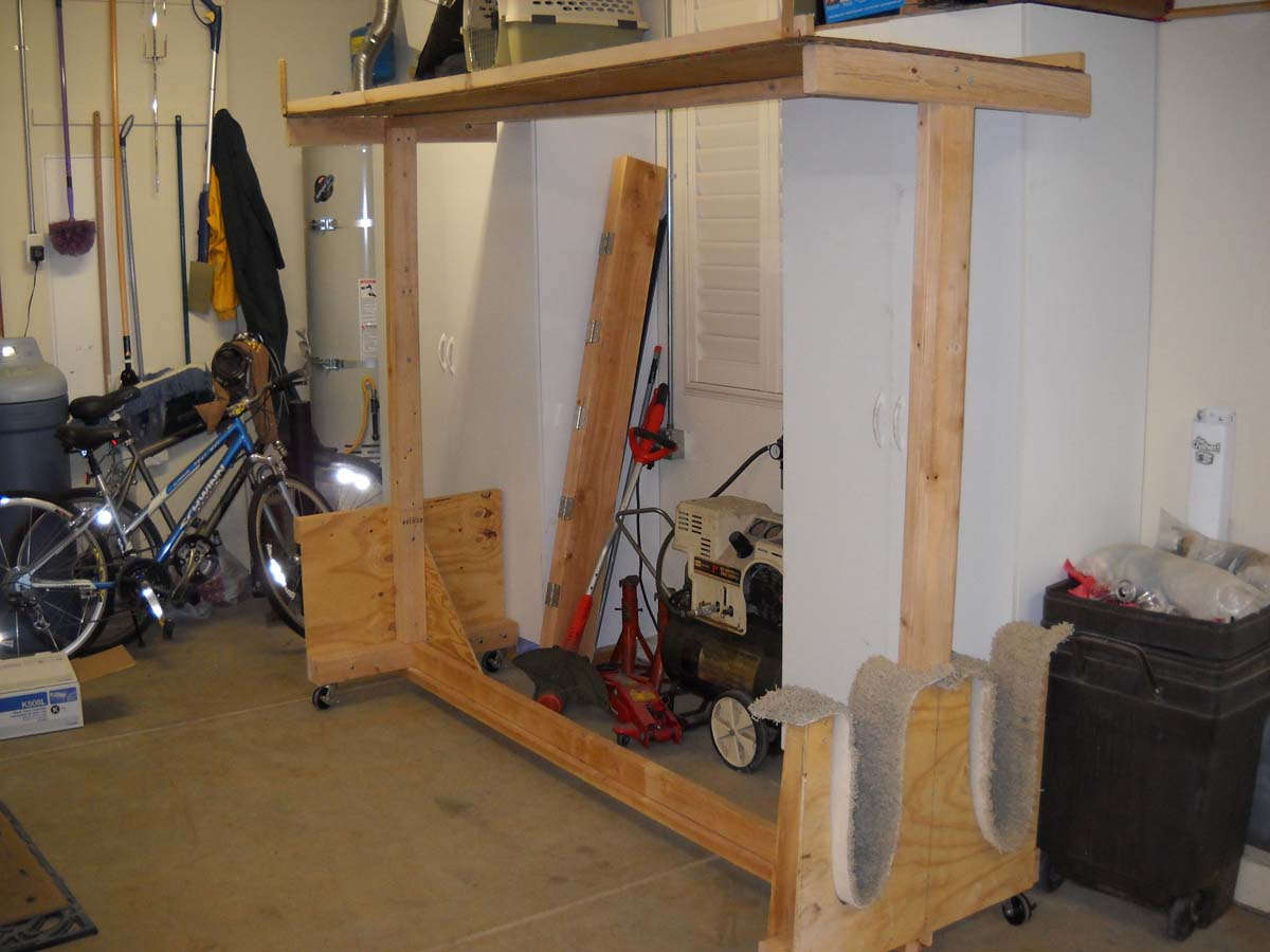
And here was the finished product. The bumpers, as it were, is just some PVC pipe stuck into fittings. The pop out if I want...not glued in.

While I was rebuilding the wing stand, I had laid the two wings on tables. It actually looked like I had two wings in my garage...I guess I did.

No photos to show of it, but then I squeezed the trailing edge rivets of both wings once they were in the new wing caddy. Easy to get to. Well, all were easy to get to except these five inboard rivets on each wing. For the life of me I can't get a good angle due to the doubler plate getting in the way. I might to do a bit of grinding on one of my pneumatic squeezer yokes to get these done. Looking at different websites on these rivets, no one else seems to have this issue. I rechecked the plans and the rear spar is correct. I'll think a bit more on this.

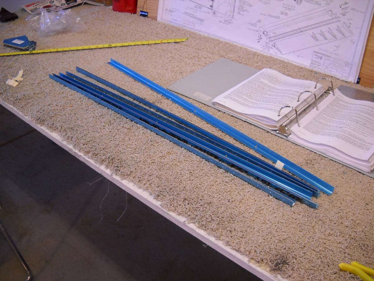
So while the wing work was puttering to an end, I started looking at aileron stuff. Here are the raw stiffeners...two ailerons have eight top and eight bottom equals thirty-two stiffeners. I stripped the blue off of the pieces and trimmed half of them. I then showed Nathan how to do it and he completed the raw cuts of the stiffeners, then used the belt sander to get them to the final shape. A turn on the Scotchbrite wheel will finish it off.
And, then on to aileron brackets. Four brackets...two inner and two outer. Took a bit to figure out because as near as I can tell the drawing is mislabeled with an incorrect part number for two of the angle aluminum pieces. Figured it out eventually.

And here are the four brackets laid out left to right. One needs to pay particular attention to rivet callouts here...the inboard brackets have five or six flush rivets, and the outboard brackets have three. It would be very easy to mess this assembly up. It still could happen...I don't have them done yet. Just ready to go as this weekend ends.
So, continued slow but steady progress. Hope to get a few more things done this week as I'll be in town. A bit of a treat to be home for the week.
March 6, 2011
Not surprisingly, did not get as much done this past week as I'd hoped, but did manage to get the aileron brackets completed, the flap brace and aileron gap seal prepped, and technical inspection of the wing and empennage to boot.
Started the week working to prepare the aileron gap seal and flap braces to be riveted on the aft edge of the rear spar. Nothing too complicated about it, but there is some trimming of the flap brace that needs to be done and is not mentioned in the instructions. I think Van figures you can figure it now. More importantly, something else not mentioned is that the surface on the flap brace that meets the lower wing skin has to be countersunk and not dimpled. This is because the flap hinge is mounted to the other side of the flap brace so you can't have dimples there. You either pick this up by a close study of the plans or happen to catch it looking at someone's website. For me, it was the latter. Glad I caught it before proceeding. Study the plans a good long time and figure it out in your head first to avoid doing something that can't be undone.
Anyway, here are the parts clecoed on the left wing after the prep work was done.

And there they are after cleaning and ready for primer...
And here are the four parts in the special paint booth...
Then, I continued work on the aileron hinge brackets. Did the preparation work on them earlier and then primed them. Now we are riveting them together, a straightforward process for the most part.
After the hinges are done, they are riveted to the aft side of the rear spar. I was consistent with the manufacturer's heads on the thinner material, the shop heads on the thicker material. Well, not entirely consistent, but pretty consistent. On one of the hinges (first one) I reversed it. It will be fine. This is the outer right wing aileron bracket riveted in position.

And this is the inboard aileron bracet riveted in position. Note the right lower rivet on the outboard angle is flush riveted, one of several flush rivets on each assembly.
And then, on Saturday morning, I had my EAA technical counselor come and do an inspection. He last saw the project in July 2009 at which time he said to call him back when the wings were to where they are now, and he would do a final look at the empennage at that point. So, I pulled out all the tail parts I put away a year ago and laid them out on tables, and he came and took a close look at all those parts and the wing structure too. 'Looks good...keep building' was the gist of his comments afterwards. No problems; I had a couple of questions and he provided some good input back. Nice guy and nice EAA program. Highly recommended from this builder with my limited experience.
So, here is how the wings looked at the end of the week. Pretty much how they looked at the beginning of the week, only a bit more done.
Next up: rivet the aileron gap seals and flap braces into position and then begin serious work on the ailerons. Also, run conduit in the wings and do the prep work on the bottom wing skins. Never a lack of things to do. My time over the next few weeks is a bit limited: a week in Dallas doing Lear 60 simulator, a week of flying, and then maybe a week of doing some recurrent training on the DC-3. Busy busy busy.
March 21, 2011
Not a lot of progress over the past two weeks...my employer wanted me to work, which I suppose is somewhat expected. Thus, I only got one day, and a partial one at that, of work in the hangar. But, I made the best of it, doing a bit of clean up work and then pressing forward. First off, I had five undone rivets left over on each wing from attaching the top skins a few weeks ago. These are the five most inbound rivets on the rear spar, and access is somewhat blocked by the doubler plate and other rivets holding the spar together. The pneumatic squeezer did not have enough room to get a straight-on surface on the rivets due to tight access, and I could not see how a bucking bar would work here. But, after taking a close look, I did a bit of grinding on one of my squeezer yokes.
With that little adjustment, I was able to get to the five rivets and set them just fine. Just like so many little obstacles in this effort, you work your way through them and get it done.
So, on to the next thing, which happened to be riveting the aileron gap seal and the flap brace on to each wing. Pretty straightfoward; I used the squeezer on the gap seal and the rivet gun on the flap brace, where access would not work with the squeezer.
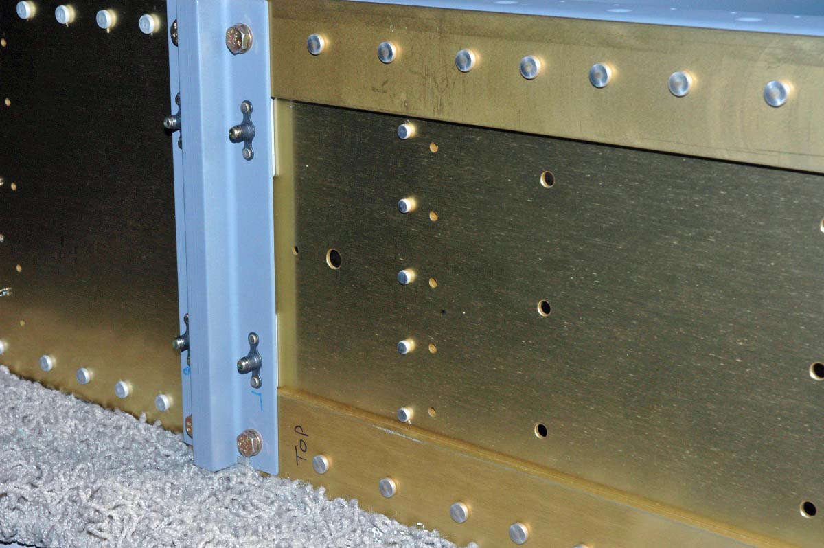
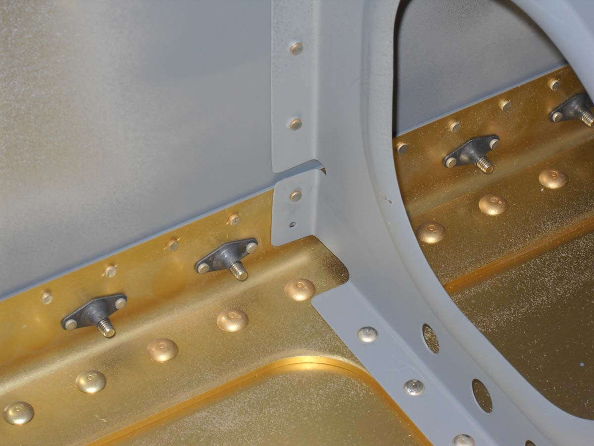
So here is my next little obstacle. I did not add a second rivet where the ribs attach to the main spar under the fuel tank. The plans don't call for it and I checked a couple of sites. There didn't seem to be a consensus on whether or not a rivet was called for here. I asked my technical counselor about it and he said I should probably add rivets...doesn't hurt. Then I did what I should have done in the first place....call Vans and ask them. I did. They said, yeah, add the rivets. Why not?
Okay, then, I will pull the tanks off (again) and add the rivets. Maybe during my next session. This is an example...the only hole that doesn't have a rivet in this photo.
Well, after all that stuff, I jumped back into the aileron construction. In short order, I finished the stiffener preparations, clecoed them into position, then match drilled them with a #41 drill. Did this on both ailerons. Marked them each and removed the bunch. Now I need to deburr the holes I drilled, then all need to be dimpled. Then, back rivet the stiffeners to the aileron skins. Maybe during my next session.
Okay, then, maybe during my next session.
April 12, 2011
I did work to place pulled rivets in those empty holes on the wing spar where ribs attached under the fuel tank. Several weeks ago I added squeezed rivets on the other side of the wing where I could get the pneumatic squeezer in, but that wasn't going to work on this side, nor was it possible to buck the rivets due to the tight area with the adjoining skin already riveted on. I found some -3 pulled Cherry rivets that worked just fine here.
Then the fuel tanks went back on, a bit harder to do since the wings were out of the big stands. So, I did it on a table that worked out okay. I had a bit of pillowing at the leading edge-fuel tank joint on both wings...a bit frustrating. I worked with both tanks a bit trying to work it down. I think it's about as good as it is going to get...not perfect but not sure what I can do at this point.

April 19, 2011
Keeping at it over the past weekend, mostly on the ailerons but a bit on the lower skins also, doing some prep work. Nathan and I spent some time Saturday morning doing lower wing skin prep work...finished the inner skins with deburring, dimpling, edge finishing, and priming the interior. I hung the outer wing skins on the wing just to get them out of the way. These will be done next weekend, if all goes as planned.
May 2, 2011
Nathan a few minutes to kill so I put him to work installing wiring conduit into the right wing. One of those smart things again....note to self: start in the middle and work towards the ends. Much easier that way.
June 13, 2011
I haven't updated for nearly three weeks; however, work continues. Though I have not been able to spend more than a few hours here and there on the project, I can say the wings are complete except for the bottom skins being riveted on, and I am well into building the first fuselage component, the firewall.
Here is Nathan running wiring conduit through the left wing.
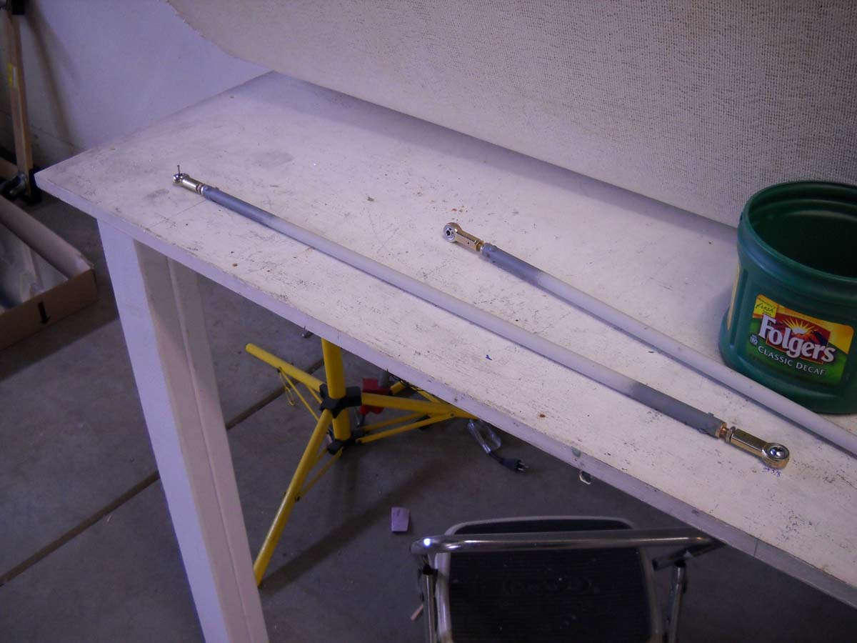
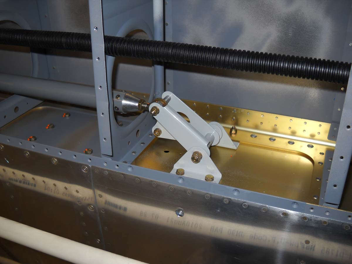
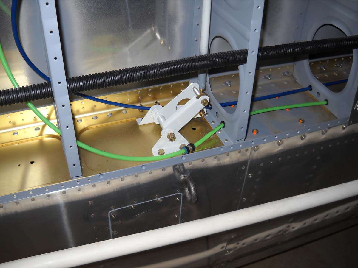
Meanwhile, while he was running the conduit, I was getting ready to install the push tubes for the aileron controls. The first thing I did was sent the length as per the plans. Very exact numbers for something that will later have to be finely adjusted again. But, being a plan follower, I dutifully set the length measurement of the two large and two small push tubes.
Then, I mounted the small push tubes between the bellcrank and the ailerons. It's a bit tricky to get the tubes connected to the ailerons as there isn't much room to work. The second one went a bit quicker. When it came time to install the large tubes that run from the fuselage to the bellcrank, I determined that I had reversed the bellcranks. So, unbolt the bellcranks and reinstall in the other wing. Oh, well. After that, the installation was straightforward.
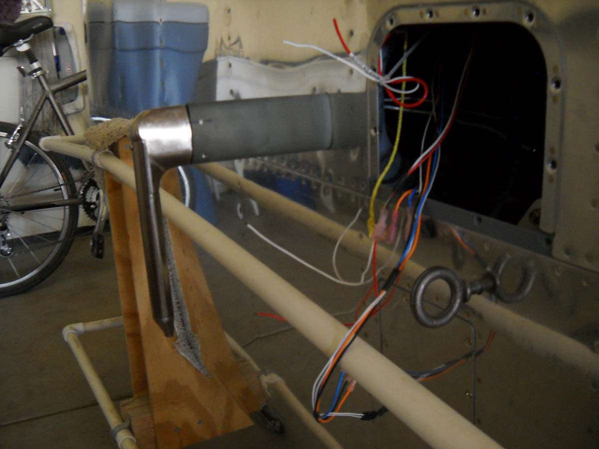
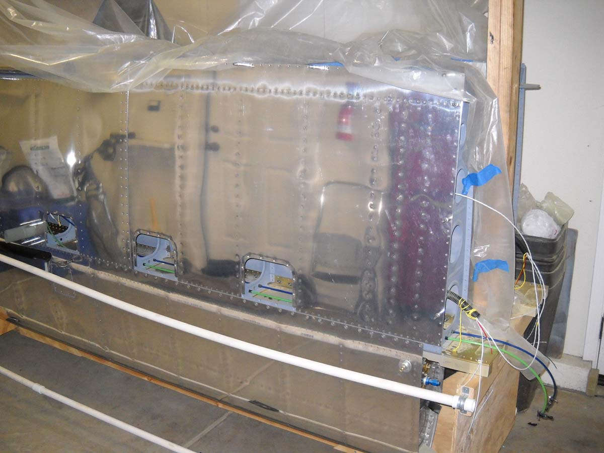
Finishing up some other tasks, I installed the pitot mast on the bottom side of the left wing. I used the template to mark out the opening in the skin for the mast. Then, I very carefully cut and trimmed, making the opening fit the mast perfectly. But, it didn't. One end is a bit enlarged. Not sure how that happened but I suspect that it is something only I will ever see.

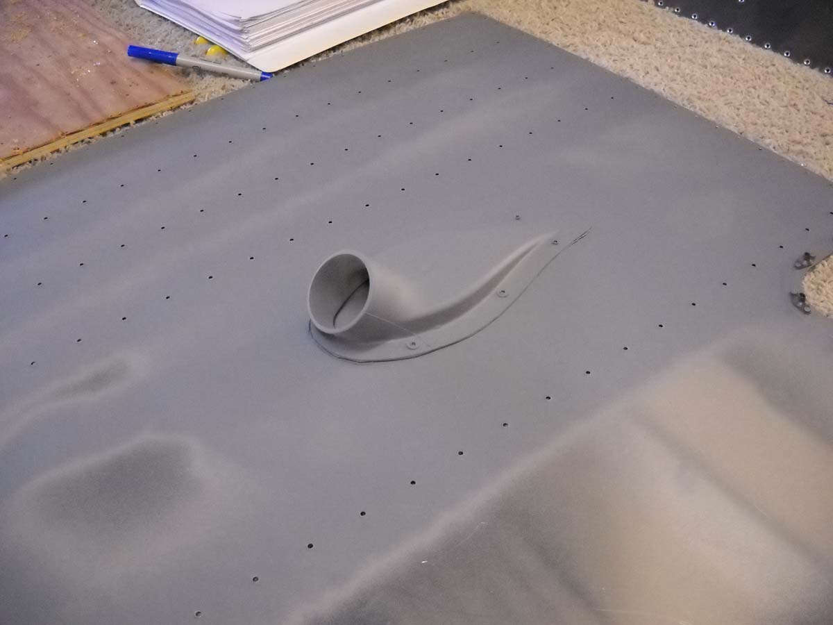
So, on to the air scoop that fits on the inside of the wing over the NACA opening on the underside of the right wing. Again, carefully measuring and clamping and then drilling. Somehow this one didn't turn out like I wanted either; the whole thing shifted about a 1/4 inch laterally between the layout and the final drilled holes. Not sure how that happened either, but I pretty much had to accept it. It isn't bad...just not how I wanted it. Attached with Pro-Seal and six pulled rivets. Later, a flexible tube will connect here and run fresh air into the aft cockpit. Someday.
I also ran the pitot and angle of attack tubes that will eventually attach to the pitot tube through the wing, using clamps at the bellcrank to keep the tubes free of the bellcrank movement.
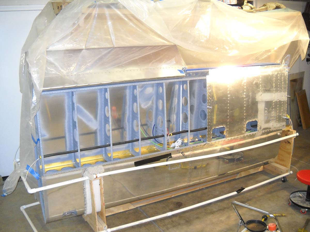
And here is a "wings done" commemorative photo, suitable for framing. Wings are done. Well, except for riveting the bottom skins on. Wings are done.
December 13, 2012
Not much done the past few weeks, what with family and work commitments. I did a bit of electrical pondering and planning, but the task at hand is getting the bottom skins on the wings riveted. My riveting partner won't be around for a while so we pressed forward and got the inner panels on each lower wing completed, and hope to get the outer ones done this coming weekend. The plans call for doing this horizontally on a table top, but it worked just fine to rivet them in the storage wing stand I have set up. No particular problems but the inner wings are hard to do because of access: the inner four ribs are tightly spaced and when one has big hands it is a tight fit with a bucking bar. It gets easier the further outboard you go.
So, here it is in progress.
And here the inner panel is riveted and the out panel clecoed ready for riveting.
This work pretty much completes the wings. All that remains will be: actual installation of the heated pitot tube; actual installation of the aileron autopilot servo; and attachment of the wing tips with navigation/strobe lights installed.
July 30, 2013
On to another little job: drilling of the pitot mast to accept the pre-drilled, slightly used heated pitot tube/AOA sensor I purchased last year. I had to carefully match the drilled holes in the pitot assembly to the proposed holes in the mast; worked fine. I also installed the pitot heat controller box in the wing, and that turned out to be a bit of a bear in the tight space I was working in. Done and done, though, at least until I apply power later.