
|
Building The Fuel Tanks |
September 28, 2010
I got serious about building the two 21-gallon fuel tanks. On the RV-8, the inboard leading edges of each wing is also a fuel tank. Building the tanks is a straight forward process, but the tricky part is making sure they are sealed so they won't leak. Tank sealant, available from Van's, is used and it is, apparently, a challenging process. There are also a few "systems" things involved, including the fuel pickup, the fuel vent, and the fuel level sensor. Plus, a couple of decisions: install a "flop tube" necessary to keep the engine running during sustained inverted flight, and the possible need for a fuel return line for a fuel injection system on the engine. All in all, another of the challenges in building an RV-8.
But, not insurmountable. I did not get a chance to spend a great deal of time working on the airplane this past weekend, but I did think a lot and worked through the process, at least in my mind. Plus, made a few of those necessary decisions.
One of the goals of building these tanks is to get the tanks set up so there is no gap where they meet the edge of the outer leading edge, nor where they meet the main wing structure. The key to this is how the "Z" brackets are prepared and set up. Each fuel tank is bolted and screwed to the wing, and the attach points for between the tank and spar are these "Z" brackets, really angle pieces, seven of which are mounted to each tank with rivets and then bolted to the spar. If these are set up correctly, the fuel tanks will mount to the wings properly. If you don't, well, lumpy and gaps. Doesn't sound good.
So, in months past I had read through the construction manual and also through another method made popular by an RV-7 guru with an incredible website that explained in great detail the ins and outs of airplane construction. This guru gave credit to earlier builders for his technique but he popularized it, and it does seem to make tank fit better than the Van's official way. Out of respect for his privacy, such as it is, I'll henceforth refer to this method as the "alternate method."
The construction techniques are a bit different, but with the alternate method the Z brackets are drilled to the tank baffle after the clecoed together tank assembly is fit onto the spar, giving you a much better chance of getting the fit correct before any riveting is done.
As for the other decisions, I decided I did not need a flop tube because I would not expect to be doing any extended inverted flight. Also, the standard experimental Lycoming engine does not need a fuel return line to the tank, and if I utilize a purge line it goes back to the fuel line coming from the tank, not the tank itself.
So, anyways, I spent an hour or two mulling over the plans and some other web sites, then spent some more time dry fitting some of the parts together. I was having a bit of difficulty understanding some of the process until I just got the parts out and fit them into position.
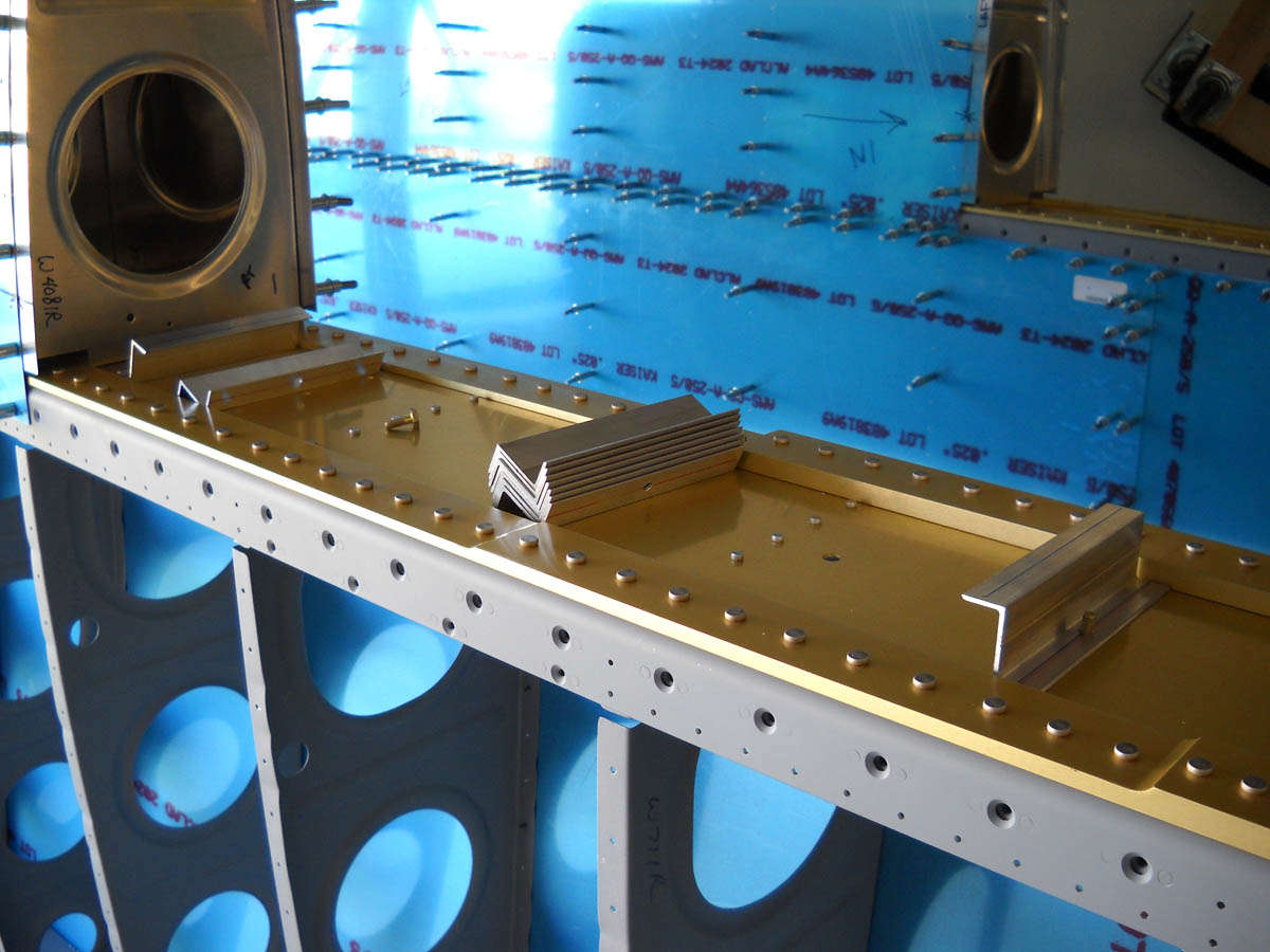
So, using the alternate method, I marked two lines on each Z bracket flange (both sides), one line offset from the center line by 1/16th of an inch toward the flange, the other by 1/16th inch away from the flange. The two offsets equal out on the bracket but allow a bit more room for using a rivet puller when riveting the Z brackets to the tank baffle. The other flange will have nut plates mounted, and these will allow the Z bracket (with tank attached) to be bolted to the spar. To make the lines easy, I used my handy dandy Edge Marker Block...actually the first time I really used it and it worked out very nicely. Thought I'd be clever and use blue ink for one set of lines and red for the other. I then drilled a #12 hole into the midpoint on the line that would be mounted to the spar. That hole corresponds with the center of three holes predrilled on the spar.
I test fitted the Z brackets on the spar, trying to get the right idea before pressing too far along. In this photo, I've drilled a middle hole in the one flange to allow it to be mounted with scrap screws to the spar. The idea here is to square it up and then match drill from the spar to properly position the other two holes on each Z bracket so that when the nut plates are mounted, all will line up when reassembled. I already knew that the most inboard bracket was set up a bit differently than the other six but somehow went ahead and drilled it anyways. After fitting them into position I saw the errors of my ways. I decided to order four extra Z brackets from Van's, piggy backing on an order I was already putting together. $2.25 each...I need to redo two of them (the inboards) and want two spares for my next, at this point unknown, mistake.
The inboard bracket, by the way, has the nut plates mounted on the other side of the spar, so the Z bracket bolts run through the flange and spar to the nut plates. The bolt holes are offset differently to allow room for the bolts to accept a socket and/or wrench for installation. Okay, then.
In my hodge podge of time I was able to spend, I also prepared the fourteen tank ribs...seven for each tank. There are five internal ribs and two end ribs for each tank but they get the same prep treatment...edge finishing, squaring up the flanges to make 90 degree angles with the ribs, and fluting to get the ribs straight. Got pretty good at fluting by the time I was done, coincidently with these being the last ribs on the airplanes I have to prepare...

And, I'd like to say I made great progress but no, I did not. I did pretty much get the rib prep process completed. A bit tedious, but it is actually pretty amazing how warped the ribs start out and how flat they end up. I think the flatter they are and the squarer the flanges are, the better the whole thing fits together.

But, I did put an order into Van's. It included two fuel pickup tubes that they sell for $15 each...to be used instead of the scratch built ones where you crimp the end and then make little sawed slots in the tube for the fuel pickup. Also ordered: a quart of tank sealant, some more AN3-4 bolts for spares, and those four Z brackets. Plus, fifty more 3/32nd clecoes just for good measure.
Finally, I also ordered two Duckwork landing lights for installation in the outboard leading edges. Got the 100 watt round light version...nothing fancy. No LED. No HID. Simple, relatively cheap. Works well. The only problem for the 100 watt lights is that they use 9 amps per bulb. Twice what the HID lamps use. But, you know, guys have been using lights like this for many decades. It seems to work. I carefully considered my options for the taxi/landing lights and made an informed decision. A leading edge landing light and a leading edge taxi light. To be installed and then move along.
Next weekend I hope to get into the fuel tank business big time. We got your fuel caps, your fuel drains, your vent tubes, your fuel pick ups, your fuel sending units, not to mention fitting and drilling the tank assembly to each wing. Still a way to go before riveting and/or sealing.
October 5, 2010
All the stuff I ordered last week showed up this week. This includes two Duckworks landing/taxi light assemblies (100 watt), tank sealant, fuel pickup lines, some bolts, some more clecoes, a tool for bending tubing, and a tool to flare tubing, plus some other stuff. The pile grows.

So, the right wing tank is now clecoed together with the ribs in place. On this past Saturday I took a lot of time to set up the baffle and tank for drilling, trying to get the best alignment and fit using the "alternate method".

The Z brackets are lined up and two more holes are match drilled from the spar to the brackets. These will later accept a bolt that will attach to nut plates on six of the seven Z brackets.

And then, using a nut plate as a template, the holes are drilled to mount each of the three nutplates to each of the six Z brackets, and then the rivets are squeezed. I used the NAS 1097 rivets here...no dimpling of the nut plates required. Then, the Z brackets can be bolted back onto the wing in their proper positions.
The seventh Z bracket (the inboard one) has the bolts going through the Z bracket and spar to nutplates mounted on the aft side of the spar. I fitted these three nutplates into position and then riveted. Did kind of a lousy job because there isn't much room to get the bucking bar in there among the ribs...a sign of things to come. I may drill one or two of those rivets out and replce them when my tungsten bucking bar arrives next week (yep...I went ahead and ordered one of those too, after these rivets caused me grief). I'm sure an experienced riveter would have no problem with these three nutplates but...

I had the tank on and off several times, trying to work out in my mind how this was all going to work. The next step here is to drill the end ribs through the baffle and through the Z brackets. By doing both end ribs you are guaranteed, according to the "alternate method," of retaining the correct alignment.

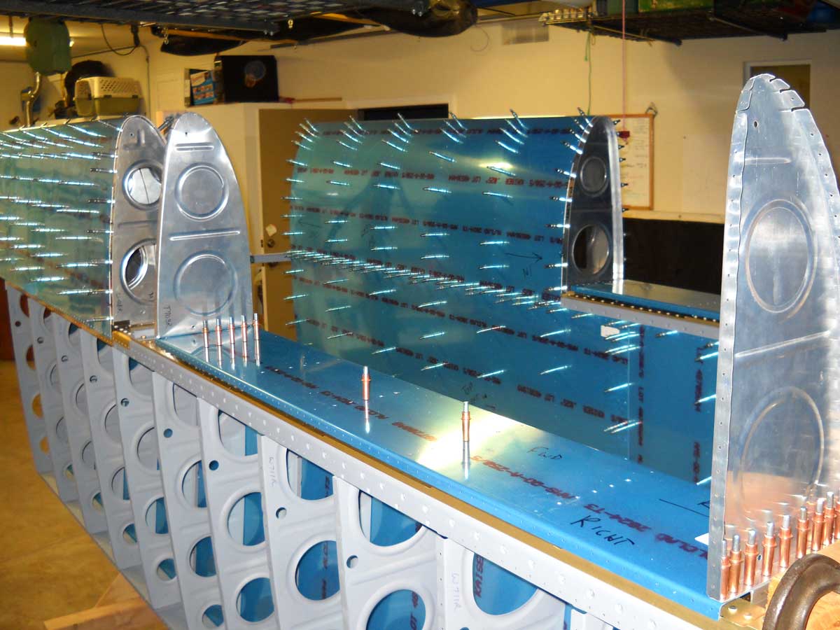
Here is another view, this of the top of the wing. As has been said many other times by many other builders..."gee, this is starting to look like a wing."

So, after carefully checking everything, I drilled the rib at the wing root and clecoed it into position.

The "alternate method" then has you fix the position of the fuel tank so it doesn't shift, then remove the outer leading edge and drill the outer tank rib. Okay then. Easier said than done because the outer leading edge does not come off easily with the fuel tank in position. Maybe I missed something, but it would be difficult to get that piece off with out shifting the fuel tank a bit.
But, I got it done thinking I had held the tank without moving it, and went ahead and drilled the outboard rib. I wasn't sure about all this, so I fitted everything back together. Sure enough, the tank had shifted a bit as the lower leading edge-fuel tank joint protruded a bit. Not happy about this. I thought a bit more about this and decided to modify the alternate method a bit.

I decided that as long as the inboard rib was correctly positioned, the outboard one was laterally correct. I very carefully shifted the tank baffle so the flanges lined up exactly with the flange on the spar and the joint plate. I used a straight edge to verify what I could see with the naked eye. Once I was very satisfied with that, I drilled the holes in the next inboard rib from the outboard rib, and clecoed it into position. I rechecked my original holes on the end rib and, sure enough, they were not lined up any longer. I thought a bit about this...either overdrill the holes and use -5 rivets or redo that Z bracket. I had an extra Z bracket but decided the oversize rivets would be okay. Actually, the holes are just a bit elongated...I'm not sure it would even be a problem as Van's instructions specfically mention elongating the holes if needed to get the best fit. Not to worry right now...I can decide later when it gets closer to riveting.
So, all this took much more time than I though it would (naturally) but I'm satisfied that when this tank comes back together on the wing it will fit correctly. We hope so, anyways.
So, the tank goes back in the cradle for drilling. All the holes top and bottom are drilled except for where the stiffeners go on the bottom. That will be done shortly.

And, then the holes to attach the skin to the baffles are countersunk on the skin. This is presumably to avoid dimpling the baffle and making it more difficult to fit the baffle into position later when the tank is being sealed. Nonetheless, this countersinking has to be done very carefully to avoid enlarging the holes or going into the baffle. I worked it out on scrap first...then drilled the holes on the skin. One or two holes were not what I wanted...a bit too deep, but overall I think it will work out okay.


So, as this evening ends, I have the right tank pretty well fabricated. Next are the stiffeners, the skin and rib prep, and setting up the fuel tank and fuel drain fittings. I can't build both tanks at the same time due to a cleco shortage, but I think I will get them both to the same point...all the prep work completed and ready for sealing...before I seal the first tank. This is an evolving process, so I may end up changing that game plan.
October 19, 2010
Pressing forward on the two fuel tanks, this past week was fairly productive...several evenings and a good part of Saturday working on them. There's a lot of prep work to the tanks prior to riveting and sealing them, and I was able to move through most of it in the last few work sessions.
I completed the Z brackets for the left wing and mounted them onto the spar.

Another view of the six brackets that get the nut plates.

For the seventh bracket, the nut plates are mounted on the spar. Here is a view of the nut plates clecoed to the aft side of the spar, plus the new little tungsten bucking bar that arrived last week. Heavy piece of small metal. I used it to set the six rivets. I'd like to say it went a lot better than the experience I had with the right wing but, no, it did not. One rivet in particular was drilled out several times. Not sure why it was so difficult, other than it is a tight location and you can't really see how the bar is sitting on the shop head of the rivet.

Once the spar work was done, I clecoed together the left fuel tank, basically following the same steps done with the right one, except it did go faster.

I then fitted the tank onto the spar and, having learned a lot from the right tank, I was able to short cut the process and was pretty confident that the fit was tight and right.

I drilled the inboard bracket through the end rib and the baffle plate once I was happy with the fit of the tank.

Then the tank came off and the holes were match drilled. A repetitive process that nonetheless goes fairly quickly.

Once the tank was match drilled, it came apart again. Next up were making the stiffeners that are attached to the bottom of each tank to add some, well, stiffness. The tank holds 21 gallons at about eight pounds a gallon, so 168 pounds of fuel. The stiffeners are cut out much like those that went into the rudder and elevator many months ago. Cut out, shaped with my belt sander, edge finished with my Scotchbrite wheel, and set aside for drilling.

And here they are cleoced to the bottom of the left wing for drilling.

Next, the fuel tank cap is positioned and match drilled. The flange that holds the cap is what is actually match drilled and fits under the skin. It has a curve in the flange to match the shape of the wing, so it needs to be carefully oriented to lie correctly. Two tanks, two fuel caps.

Next is the underwing fuel drain that sits inboard and aft, at the lowest point of each tank. This allows any water that gets into the fuel, either by condensation or precipitation, to settle to the lowest point of the tank, said water being heavier than fuel. So, it can thus be drained. Two tanks, two fuel drains.

Moving on to deburring and dimpling; all the ribs and all the skins and all the stiffeners need to have each drilled hole deburred and dimpled. I had purchase tank dimple dies months ago, and now can finally use them. The dimple dies create a dimple that, get this, is .007 inches deeper than the standard dimple die. This allows room for a bit of tank sealant to set under each rivet without causing the rivet to be "proud," that is, stick up above the skin by, let's see, I guess .007 of an inch. Anyways, the ribs were dimpled using my pneumatic squeezer, an invaluable tool if there ever was one.

The left skin on the work bench being deburred, and then the edge holes can be dimpled using the squeezer. A word to the wise: don't deburr the inside of the holes countersunk in the thin skin earlier, those holes that match up against the tank baffle. Those holes are very easy to enlarge if you dimple even gently. These holes might best be deburred by just using a Scotchbrite pad. Before deburring and dimpling, the blue plastic sheeting was removed from those areas.

The right tank skin deburred and the edge holes dimpled. I'll use the DRDT-2 to dimple the interior rib holes.

Along the way, I was able to get the tank access holes cut out of my inboard ribs using a fly cutter. Some guys who are real airplane mechanics helped me out with this since they had the drill press and the fly cutter and actually knew what they were doing...thanks to Greg and Kevin and James.

Preparation work on the ribs is just about done here, except for the work on the tank access cover plates.

I also had to build two little clips for that will hold the fuel vent line at the highest point in the fuel tank, which would be near the fuel caps on the outboard part of each tank. Cut a little piece of metal out and shape it to the right size. Used a 1/4 drill to help form it, plus a pair of seamers.

Worked out just fine.

Ended my work sessions this week spending some time on those tank access plates. The plate is held onto the tank with nut plates that are riveted on to a reinforcing plate mounted inside the tank. One of the peculiar things about this is a tooling hole that invariably is located very close to a rivet. Logic would suggest you could rotate the plate a bit to avoid the close rivet, but the thing is, the fuel capacity float sending unit is mounted to the plate. If it is rotated a bit, it won't be vertical in the tank, and the fuel level would, by my reasoning anyways, not as accurate. So, my decision is to leave the plate where Van's wants it, but use tank sealant instead of a cork gasket to seal this area. Should work fine.

So, that's where I am right now. Working on the cover plates and their associated fuel level sensors and fuel pickup tubes. Then, I have some final preparation and cleaning to do before starting the sealing and assembly process. Hope to get to that in my next work sessions.
October 28, 2010
So the past ten days have allowed me to move forward on the fuel tanks, even to point of using tank sealant, finally, and beginning the final assembly of each tank.
Started the sessions doing more preparation work, in this case dimpling the interior rivet holes on both sets of skin.

Then, with just about all the prep work done, I got busy with doing a thorough cleaning of the interior skins and some other parts soon to be put together. Started by using a hot soapy water with Palmolive dish soap, then rinsing for several minutes, blow drying with pressured air, then wiping the whole thing down with naphtha. I'll try and avoid touching the material now with anything other that my hands covered by latex gloves, just to keep skin oils from contaminating the clean surface. Here are the skins about ready to go.

I did a similar cleaning of the other parts I was going to work with over the subsequent sessions, including washing the rivets to be used in naphtha, then setting aside to drain and dry.

Then, following the lead of others, I masked off the area where the stiffeners were going to be attached in order to have a bit better control of the tank sealant. This is particularly important in the area where the ribs are going to be attached to the skin. I didn't want to have a bunch of sealant spread into those areas. I used rubber-like electrical tape as masking tape.

It was too late during that session to get into actually mixing and applying the tank sealant, so I took some time and did some more work on the forward tank mounting brackets that attach to the forward part of each tank interior rib where it meets the fuselage. I had done some more rough cuts on a bandsaw and used a belt sander to get it close. I got it a bit closer still with a belt sander this day, and then used the Scotchbrite wheel to finish it up. The other pieces are the reinforcing plates, two of which end up being riveted on the backside of the skin holding the mounting brackets, and the other two are riveted to the forward part of the outboard tank rib. Stiffens things up a bit, presumably.

So, with a bit of trepidation, I started the next session with actually mixing up some sealant and getting to work on the stiffeners. There is so much written about this stuff, how it scares builders and sometimes turns into a huge mess. Nothing but problems and for some; they cannot abide the stuff. I was cautious but approached it in an organized manner and heeding some good advice from TWHGBM (those who have gone before me). Mixed up my first concoction with 5 ounces of sealant and 0.5 ounces of hardener. I began learning lessons, which I will expand on below, but up to now, the stuff has not been that bad. Messed things up only once or twice, but recovered.

I should have taken a photo of the stiffeners after I had put them into place and started riveting. This is the best I did... However, that process was straightforward and pretty much as planned. A few observations...this sealant is thick and hard to handle. I "buttered" up the stiffeners with a good layer of sealant and placed them into position. On the first skin, I did six and then riveted, then the last six and riveted. On the second skin, I did all stiffeners at once. The riveting is messy and you can't really see how the rivets turned out. I probably used more sealant than I needed to but not excessively. All we are doing here is keeping fuel from leaking out the rivet holes so it really should not take all that much. I will go back and add a dab of sealant to each of the shop ends of the rivets later.

Here's how the rivets turned out after I did the clean up. Of course, the rivets are held in by rivet tape during the riveting, and a bit of sealant comes out when the rivets are driven. Once the clean up is done, though, it looks like any line of rivets.

The fly in the sealant, as it were, was the first fuel tank flange I did. It was during the same session as I did the stiffeners and thought I'd use up the remaining sealant and do the flange. Hurried a bit more than I wanted to, and used the rivets called out by the plans...426-3-4s. I "wet" set the rivets, then buttered the flange and put it in position.

When I actually did the rivets, though, it was obvious after the first one or two that the rivets were too short. Why I didn't stop right then is my own personal mystery but when I did all the rivets I could tell I had a problem. They were not going to work, so I realized I would have to drill all the rivets out and do it quickly before the mess got worse. I did the drilling, complicated by my desire to avoid getting metal shavings into the wing interior for the other fresh sealant. The drilling went pretty well...got the flange off and cleaned off the sealant with MEK...carefully. Cleaned up my big mess and took stock. I didn't actually do anything else that session except clean up and inspect what I had.
The next session though, I decided to enlarge the holes with a #32 drill and use NAS rivets to fit the existing dimples. Did all that and it turned out much better, but had two rivets a bit "proud." I considered leaving them because they sat just a bit high, but thought about all the times I'll fuel the airplane and look at them. I drilled them out too, and reset them. Not perfect, but certainly well into the acceptable range. For me, anyways.

I did the second fuel tank flange using 426-3-4.5 rivets and that worked out a whole lot better. Lesson I learned again: fit and carefully fit again, then assemble.
Moved on to the fuel tank drains, one for each wing. Fairly straightforward but the rivets were, in this case, too long. The first one was not great work; I wasn't happy with the rivets but deemed them acceptable considering what they are used for. Cleaned up, here is what we ended up with.

So, as I end these sessions, I am now up to the part where I start putting the ribs into place. So, this coming Saturday, I hope to butter up them ribs and get them into position. Then, I'm going to let them set up for half a day and then rivet the whole mess together. I actually hope it's not a mess.
November 2, 2010
This past week started well but ended with a bit of a whimper on my progress. Oh well, that's to be expected. However, still a bit frustrating and discouraging.
I began with the intent to finally seal and rivet the five interior ribs of each tank, but before jumping in to that, I needed to encapsulate all the rivets of the stiffeners with a bit of sealer. I tried loading a plastic syringe I got at Tap Plastics. This worked better than I thought. I mixed up about 3.0 ounces of sealant and carefully filled the syringe. Cleaned it up and this was the result.

Worked pretty well as far as I'm concerned. I put a dab of sealant on each of the stiffener rivets to completely seal them. I got a bit better at metering out the right amount as I proceeded.

So, here is the interior skin of one tank ready to proceed with adding in the ribs.
After researching the best way to do this, I decided that Rick Galati over at the Van's RV Forum site has the best idea. See here also. He's worked with this sealant professionally and has a lot of experience with it. His idea is to seal all the ribs at once, and cleco every hole. Let it set up for 24 to 48 hours, then come back and remove every third cleco, wet-seal the rivets into the holes, and then set them. Much neater, much more organized. Sounds good even if it is a bit contrary to the Van's instructions.

But, here we go. I "buttered" up the nose of each of the five interior ribs and clecoed them into position. This worked out very easily; more than I expected.

Here is a closer view.

Then, I completed the buttering of each rib on the top, and clecoed it into position. Then, I flipped the thing over and did the same for the other edge of the rib.

And, so, here is the left tank clecoed together. No rivets, but all the ribs are in place with sealant and the fillets are done.

I confess I chickened out a bit and started to rivet after about twelve hours, but only the top of the tank rivets. The sealant was still pretty messy, but less so than it would have been. It would have been fine to wait at least 24 hours to do any riveting.
However, part of the problem I had during this past session was just one of time and underestimating how much time this whole process would take. It took me two hours to assemble the tank's five ribs, and then a total of about three hours to actually rivet it together. The thing is, you are sort of committed once you get into this process. I had envisioned I would be able to do this work on both tanks, but other life things also need attention. Also during these sessions I had hoped to complete the end ribs and get them ready to be added to the tanks.
After feeling rushed on Saturday afternoon with the first riveting of the top of the tanks, I felt even more rushed on Sunday afternoon with the bottom of the tank. I had no time to do the end rib prep work, let alone touch the right tank ribs. I decided to take some time Monday night and the end ribs, and finish encapsulating the rivets I already drove on the left tank.

So, Monday night I dove in, somewhat pressed for time again. I had already decided to seal the backing mount for the tank access covers, so was working on that. As I pushed forward to get this done, I felt rushed again and wasn't doing that great a job. When I checked the quality of the rivets, it became obvious that the sealant was making more than a few a bit on the "proud" side (flush rivets extending above the matching surface) and would, will, have to be redone. I decided to quit for the week before I messed anything more up. I just cleaned up and put things away. It will be there next weekend. At this pace, it will be many weeks before these two tanks are done.

So, here's the current status. The left tank's interior ribs are sealed and riveted. The two interior ribs, left and right, have the nutplates riveted but many rivets will need to be drilled out and replaced. One of the outer ribs is ready, the other one still needs to have its tooling hole covered. No assembly work has been done on the right tank yet. Slow, slow, slow. November 9, 2010
More work on the fuel tanks over the past week. I corrected most of the little "quality control" issues left over from last week, moved though a bunch of things, created a few more "quality control" issues, but ended the week quite a bit further along on the tanks.
When we last met the end ribs, I had done a marginal job on the flush rivets holding the nut plates on for the tank access cover. So, I began my Saturday by drilling out the substandard rivets and then resetting them. Done and done; looks much better.

The other side of one of the inboard ribs. I used sealant on the back of the nutplates; not sure exactly if this is going to help much but I decided not to use the cork gasket and had a tooling hole to fill. Still, also, done and done.

I also completed the work on the outboard end rib, making a patch for the tooling hole in the forward part of the rib.
So, then I was ready to move on to work on the right fuel tank. I hoped to do all the sealing on the ribs and cleco together the whole thing. Then, let it set up and rivet on Sunday and/or Monday afternoon.
So, here are the interior ribs partially "buttered" and clecoed to the skin at the leading edge.

Here, the bottom of the ribs are clecoed in with the sealant applied. Using this method, it is relatively easy to create the fillet on the part of the rib that is in position.

And, here is the top side of the right fuel tank clecoed together and setting up for riveting.

So, Sunday came and went without much work done; mostly I worked to rivet one of the end ribs on the left tank into position and then set up the other end rib for riveting on Monday.
Then, on Monday, I spent the better part of five hours doing all the riveting on the right fuel tank and riveting the end rib on the right tank, to complete the basic skin to rib work on both tanks.

Most of the work with the rivet gun and the pneumatic squeezer went okay; some was not as good as I wanted. I drilled out about six rivets and reset them. Still a few that are not where I want them to be, but I suspect this is mostly cosmetic. These less than great rivets sit a bit proud, probably from the sealant in the dimples. But, overall, they turned out pretty well.

So, here is the left tank set in the cradle, with the tank baffle resting in position for riveting, maybe by next weekend. These tanks have taken a long time.

Still to go on my two tanks, in this particular order: do a quality check on each rivet, then dab some sealant on each shop head rivet to ensure a leak free rivet; next, do the same with each fillet to make sure all are secure. Then, install the fuel vent line and flare the end for the fitting through the inboard rib. Then, set up the fuel sending unit and mount on the tank cover plate and do the same with the fuel pick up line. Then, do the prep work on the baffle and, eventually, seal and rivet the baffle and "Z" brackets into position. Piece of cake; almost done (right).
November 14, 2010
Continuing with the fuel tanks....as I have not been able to spend a whole lot of time on the project, progress remains slow. Over the past week, though, I did most of the finishing work on the tanks, almost to the point where I will install the rear baffle and complete them structurally.
Among the tasks was the installation the forward mount plate to the inside ribs on both sides. This needs to be riveted in after the rib is installed to allow the rib rivets to be set. So, the brackets are thus mounted on each tank.

Here is another view of the bracket installed and the individual rivet heads treated with a "dollop" of sealant.

That "dollop" of sealant is added to each rivet head on the interior of the tank. I was a bit heavy on the sealant, more than I wanted to be, but it is, as they say, what it is.

I learned how to use my flaring tool this week and flared the fuel vent line where it attaches to the fitting that goes through the inner rib. In this view the tank is inverted. More globs of sealant, again more than I probably should have used, but that fitting is sealed.

The fuel vent line allows air to flow in and out of the tank as fuel is drained out, and also allows for fuel expansion if the temperature rises. The fuel has somewhere to go and the air has somewhere to come. Here is where the fuel vent line terminates...at the fuel cap in the little bracket purpose made. Again, the tank is inverted here. When the RV-8 is level, this is the highest point in the fuel tank, which is why the fuel vent line terminates here.

On to the fuel tank sending unit, which for me is the standard float type gizmo. The wire is bent as per the plans and mounts into the sending unit which, in turn, is mounted to the fuel tank access plate. The float rests about 3/4 of an inch from the bottom of the tank when it will indicate "empty." That might bug some guys, but I won't mind having a gallon or so of fuel left in the tank when it is reading "empty."

This is a bit of a concern for me. The float assembly is actually designed to be mounted horizontally at the top of the tank, at least if the float assembly plans are any indication. When it is mounted vertically, as in the RV-8, it seems to me it would have a natural tendency for the float assembly to float right off the sending unit when the tank is full of fuel. That's the only place where it could come off, but I plan to have full fuel tanks once in a while. I think a bit of adhesive here would work pretty well, but I will ponder and question a bit more before proceeding.

So, that's where I am now. I should be able to install the tank baffles next weekend and add the brackets. Then it will be a matter of installing the tank access plates with the sending units and fuel pickups installed on the plate. Let the sealant cure for a week or two, and then test each tanks for leaks. On we go.
December 20, 2010
Over a month since I updated this site. I've not had much time to work over the past five weeks, but I have had a few solid sessions, so progress is still being made. I have continued to work on the fuel tank, particularly completing the assembly of the right tank. As of today, both tanks are structurally complete and sealed. The only thing left to do is to attach the tank access plates for both tanks, let that cure, and then do the leak tests.
Continuing with work on the left tank, I carefully laid out how the Z brackets were to be oriented on the tank once the baffle was installed. I double checked it and, sure enough, I had one backwards. Part of the reason is that I was used to looking at the plans from the tank perspective; now we are looking at the tanks as they are installed on the wing.

No photos of assembling the baffle onto the left tank. However, it was fairly straight forward. As recommended on other sites, I laid the bead of sealant on the mating edges of the tank, but then added another thin bead on the baffle itself. Seemed like a good idea.
Here is the nearly finished tank back on the wing.

And another view. The mating joint between the outboard leading edge and the fuel tank is a bit of a concern for me as the tank seems to sit a bit higher than the leading edge section. However, I have noted that many other builders have had similar concerns and it is a bit too early to tell. I'll need to wait until the leading edge section is riveted up with the joint plate installed with nut plates to get a better idea.

Jump forward a week or two and here I am getting ready to close up the right tank. This shows baffle preparation....deburring the holes, edge finishing, and cleanup.

Here is the right access panel with sending unit mocked up for fit. I did a better job on the right sending unit with the wire bend and all. I followed the plans on the left one but the plans were off a bit, at least in my opinion. I adjusted the distance between the sending unit and the ninety-degree bend (shortened it) and it fits better.

Adding a bead of sealant to the baffle. Laid everything out carefully and then, when finally ready to mate the baffle, got distracted and first put it in 180 degrees out, basically upside down. Made a bit of a mess I didn't need to make. It worked out but I kicked myself a bit once again for not triple checking something before I pressed ahead.

Here are the Z brackets being added to the baffle. Pulled rivets hold the brackets on and go through the baffle to the underlying rib flanges. No longer any any access to the inside of the tank so the pulled rivets are used.
On the ends of the tank, both outboard and inboard, the brackets are held on with AN470AD4-5 rivets. I had "ovalized" the outboard holes a bit early in the tank layout process when I adjusted the fit, so I enlarged the holes to accept AN470AD5-5 rivets (next diameter size up), and set them. Problem solved.

And the nearly completed right tank sitting on the wing. It's a good idea to let the tank set up vertically like this to let gravity help the sealant set up where it needs to be...against the baffle and the mating surface. It sat here for a week before I could get back into the project.

This past Saturday I spent a few hours doing two things. First, I drilled out seven rivets from the right tank and replaced them. They were a bit on the proud side and I wanted them flush, so out they came.
I then did the final work on the two access plates...mounted the nut plates that hold the fuel sending units, and then putting everything together with sealant.

And, thus, here are the two access plates put together and sealed, awaiting installation onto the tanks themselves. The fuel pickup tubes have the anti-rotation bracket installed, which prevents the pickup tube from rotating and also keeps the nut holding the tube to the fitting from loosening.
I'll install the plates in the next day or two, as I am on a pre-Christmas vacation, as it were. I will then let the sealant cure, and then do the leak tests. The tanks are not 100 percent done, but getting very close. Then I can bid the tank sealant goodbye for awhile. Okay by me.

I am moving back to working on the outboard leading edges. Assemble, rivet, and attach.
December 27, 2010
I started the week by installing the access plates on both fuel tanks. Pretty straightforward. I'm using the hex screws for both the fuel sending unit and the access plates; makes it easier to remove later if necessary.
Here's one of the tanks gooped up with sealer awaiting the installation of the plate.

And with the plate installed.

Both tanks on the wings and basically complete, at least until I do a leak test on each one in a week or so.

January 12, 2011
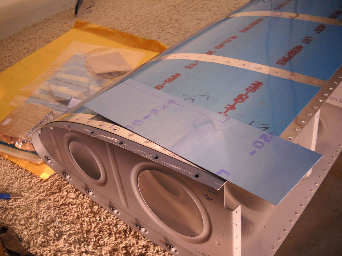
Speaking of fuel tanks, I jumped out on New Year's Day and figured I would test fit the completed leading edge with the fuel tank mounted on the wing spar. I was a bit disappointed with some minor "pillowing" that occurred between some of the forward screw holes on the forward, most curved section of the leading edge. Nothing unusual here, from looking at other web sites, but still something I hoped I could avoid. I spent the whole morning trying to get it to fit better, and ended up making a shim that was installed through the curve. It helped a bit, but not as much as I had hoped. More later, but here is a photo of the shim being measured and cut.
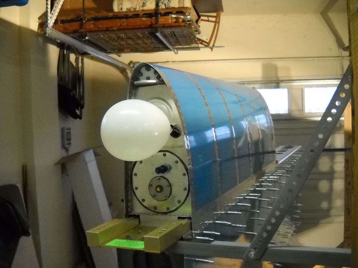
Ah, the fuel tank test. Not sure this is how Boeing does it, but it seems to work. What one needs to remember is that the balloon is not a leak indicator but a pressure relief valve. The point is to pressurize that tank to allow a check for leaks, but not to literally blow the tank up with too much pressure. The balloon works, thank you very much. Unfortunately, during my check, I did find one small leak where baffle and skin come together. More on that later, when I try and fix it with minimal tank invasion (MTI). The other tank seems to be okay.
The tanks are essentially done, and in my mind I consider them done. There is that one little leak issue that I will resolve. I'll try and detail that a bit when I get to it.
January 31, 2011
Got a good day in last Saturday but, of course, did not get as much done as I had hoped. We are close to having the bottom skins ready to be riveted on but this is not a quick process, especially with one day a week to work right now.
However, I started with the fuel tank, trying to fix the small leak detected in the left tank a few weeks ago. The leak was on the baffle to skin joint. I had read on the Van's Air Force forum about a technique to try...so I tried it. Basically, you create a suction in the tank and try and draw diluted sealant into the leak area, thus sealing the tank. Here is the area I marked on the tank where the leak was.

To make this work better, I drilled out some perfectly good rivets from the area, seven to be exact. I wanted to increase the void where the sealant was to be drawn in.

Then, I created the vacuum with a shop vac sucking from the fuel tank opening. I was careful not to make a good seal and used the vent line to also allow some suction but not too much. I cut the sealant with a bit of MEK and applied it. Not too impressed with the process, but we shall see. I used some clamps to hold everything relatively tight.

I reset the seven rivets the next day. Like I said, I'm not sure this is going to work. If it doesn't, I'll probably cut an access hole in the baffle, seal the leak area, and patch the access hole. Stand by....I'll test it again next weekend.